
GPU Gems 2
GPU Gems 2 is now available, right here, online. You can purchase a beautifully printed version of this book, and others in the series, at a 30% discount courtesy of InformIT and Addison-Wesley.
The CD content, including demos and content, is available on the web and for download.
Chapter 28. Mipmap-Level Measurement
Iain Cantlay
Climax Entertainment
In the original GPU Gems, Cem Cebenoyan asks the question, "Do your users ever get to see your highest mip level?" (Cebenoyan 2004). If the answer is no, performance can be enhanced and memory can be saved by swapping those unused mipmap levels out of video memory.
One approach to answering this question is to substitute a "false-colored" mipmap and then render the scene. Such a mipmap is one in which each mip level has a different, contrasting color. Figure 28-1a shows a view of some textured terrain; Figure 28-1b shows the same view substituting a false-colored mipmap. Although the viewpoint is that of a character standing on the terrain, it is easy to see that the highest-detail yellow mip level is hardly visible.
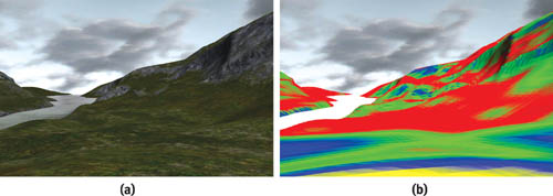
Figure 28-1 Applying a False-Colored Mipmap to a Terrain
The false-coloring technique is useful for authoring art assets, but it requires a person in the loop. This chapter shows how we can use the GPU to automate the process. The technique can then be extended to the more general question: Which mip levels are visible?
Our GPU-based approach is efficient enough to be used in a game engine. Thus, the visible mip level can be dynamically fed back into the engine's texture management routines to reduce memory consumption. The memory that is saved can be used to increase texture resolution elsewhere, improving the richness of the scene. We recently applied the technique to terrain in Climax's Leviathan engine, producing texture-memory savings of 80 percent, with no detectable loss of visual quality.
28.1 Which Mipmap Level Is Visible?
The GPU's choice of mipmap level depends on many factors: screen resolution, antialiasing settings, texture-filtering options, anisotropy, clever driver optimizations, the distance to the textured polygons, and the orientations of the polygons. These factors are mostly under the user's control, especially in highly unpredictable situations such as online multiplayer games.
In theory, all the factors can be analyzed on the CPU, allowing us to predict the GPU's choice of mip levels. See, for example, Williams 1983 for information about the theory of mipmapping. However, there are several practical difficulties if we wish to apply the mathematics in an application such as a game.
First, it is not always possible to know all the variables. Antialiasing and texture filtering options can often be overridden from the control panel. It is difficult or impossible for the application to determine these settings.
Second, although the theory of mipmapping is widely understood, GPUs are much more complex than the theory. They contain optimizations and enhancements that are usually complex and proprietary.
Finally, modern scene complexity defies efficient real-time analysis on a CPU. Computer graphics texts describe the mathematics of mipmapping for a single polygon. Current 3D applications display objects that use tens or hundreds of thousands of polygons. Although we could analyze the orientation and screen-space size of the polygons in a 100,000-triangle character mesh, doing so would unnecessarily consume lots of CPU power.
28.2 GPU to the Rescue
Fortunately, the GPU excels at analyzing a 100,000-triangle mesh. It does not have an explicit function that reports which mip levels will be used to draw a mesh, but it does implicitly perform this analysis every time that it draws an object. [1] The result is not explicitly available in the form that we need, but it is implicitly there in the pixels that appear in the frame buffer. The trick is to somehow analyze those pixels and convert them into a result of the form "mipmap levels 0 and 1 are not required."
28.2.1 Counting Pixels
Consider the false-coloring example cited in the introduction. Our approach is loosely based on automating this process.
We could false-color a texture, render the object, and copy the frame buffer to system memory. The various colored pixels could then be counted to give an analysis of the visible mip levels. Though this is possible, it is not fast. Copying from video memory to system memory is currently prohibitively slow. Note the "currently": PCI Express changes the speed of video-to-system memory transfers. Even so, using the CPU to count frame-buffer pixels is likely to be inefficient.
The GPU, however, can efficiently count pixels using occlusion queries. (Strictly speaking, it counts visible fragments, but the distinction makes no difference to our approach.) An occlusion query indicates how many pixels of a draw call passed the z-buffer test. That test cannot be used to directly analyze our color frame buffer, but it can be made to work if we rephrase the problem.
Is the First Mip Level Visible?
First, return to the simpler initial question: Is the highest mip level visible? How can we answer this with an occlusion query?
Fortunately, occlusion queries take into account all of the render state in the pipeline; that includes the alpha test. Our approach exploits this: we create a special calibration texture with opaque alpha (1) in the highest level and translucent alpha (0) in the other levels; we enable alpha testing with a reference value of 0; we render the target object, substituting the calibration texture; and we create an occlusion query for the draw call. The alpha test rejects any entirely transparent pixels and passes any with alpha greater than 0. So only those pixels that have sampled the highest mipmap level are counted by the occlusion query.
Figure 28-2 illustrates the result on a piece of terrain. Figure 28-2a shows the original terrain; Figure 28-2b shows a version rendered with false coloring and opaque alpha in all mipmap levels; Figure 28-2c shows the same object with opaque alpha in only the top, yellow mipmap level. The more distant parts of the terrain (and the flatter parts) do not sample the highest mipmap level; therefore, the output alpha values are entirely transparent (0) and the pixels are not rendered.
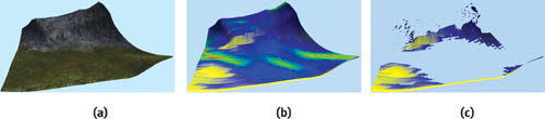
Figure 28-2 Applying the Test to a Piece of Terrain
Extending to Multiple Mipmap Levels
We can use an occlusion query to determine if any given level of a mipmap is visible. To determine which level is visible, we simply repeat the process for each mipmap level that we care to measure. Our goal is to save texture memory, so it is not necessary to measure all the levels in a mipmap. Significant savings will result if we can avoid the highest few mipmap levels. For example, in an uncompressed 512x512x4-byte texture, the highest four levels consume 1 MB, 256 kB, 64 kB, and 16 kB of memory (or 100 percent, 25 percent, 6.3 percent, and 1.6 percent). The third and subsequent levels are insignificant.
Rather than create a calibration texture corresponding to each measured level, we use a single texture and fill successive levels with decreasing alpha values. Figure 28-3 shows a sample calibration texture. Linear mipmap filtering will thus produce a continuous gradient of alpha values through the top four levels, as shown in Figure 28-4.
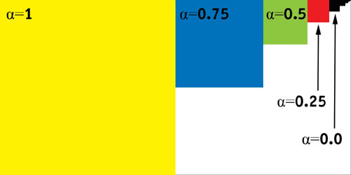
Figure 28-3 The Calibration Texture

Figure 28-4 The Alpha Gradient
Only the alpha values are important to the algorithm; the different RGB colors in each level are useful for illustration and debugging.
We could test each mip level against a different alpha reference value. However, we instead choose to keep the alpha test constant and use a pixel shader to offset and scale the alpha value differently for each level:
ps .1.1 tex t0 mov r0.rgb, t0 + sub_x4 r0.a, t0, c0We set c0 to 0.75, 0.5, 0.25, and 0.0, respectively, for each of the four levels that we measure. The alpha values of the level that we are measuring are thus remapped to the [0,1] range. Scaling the values in the pixel shader means that each level uses the full range of values possible in the alpha test.
We also create a baseline reference query that is used to count all of the test object's pixels without any alpha test. This value is required for interpreting the results.
Interpreting the Results
Visually, the results of the draw calls might look like Figure 28-5. The occlusion queries return a set of pixel counts for each level and the reference. They are typically something like the following:
reference : 13000 level 0 : 0 level 1 : 650 5 % level 2 : 10530 81 %
    level 3 : 13000 100 %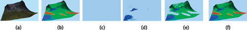
Figure 28-5 Draw Calls Used to Measure the Visible Mip Level
We run through the levels searching for the highest one that exceeds a significance threshold; this is deemed the first visible level. The threshold corresponds to the visual significance of the mip level in the output. By default, we use a threshold that is 15 percent of the reference value. Figure 28-6 shows how little visual fidelity is lost for low thresholds, while the image becomes progressively blurrier as the threshold increases.
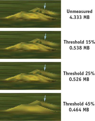
Figure 28-6 The Effects of Varying the Threshold
Using the Results
Having measured the mip level that is displayed on an object, how can we use the result? In Climax's Leviathan engine (Climax 2004), we use the results in two ways.
First, we use Direct3D's managed resources. Therefore, we can pass the mip level to the resource manager using IDirect3DBaseTexture9::SetLOD. Simply making that function call will cause Direct3D to save video memory. (We highly recommend using managed resources.)
Second, our Leviathan engine supports a massively multiplayer online game. Contrary to recommended practice, we have to generate most textures on the fly while the game's rendering loop is running. For example, player characters have to be loaded on demand at arbitrary times. Thus, we use texture mip-level measurement to drive some on-the-fly texture generation. In addition to saving video memory, this also saves the system memory copy that Direct3D keeps, and it saves the cost of generating unused levels.
28.2.2 Practical Considerations in an Engine
The concepts behind measuring mipmap levels are simple, but applying the idea in practice, in a real-time engine, is not so straightforward. The implementation in Climax's Leviathan engine has required several revisions over a period of more than a year.
Emitting Modified Draw Calls
To measure the mip level of an object, we must redraw it with altered render states. We must override the following:
- The pixel shader
- The alpha-test render states (D3DRS_ALPHATESTENABLE, D3DRS_ALPHAFUNC, and D3DRS_ALPHAREF)
- The texture
Additionally, D3DRS_COLORWRITEENABLE is used to ensure that the calibration objects do not appear in the frame buffer. Fortunately, disabling color writes does not affect the results of the occlusion queries.
The design of the Leviathan engine naturally supports overriding states in this manner. Each draw call is buffered and stored as a vector of abstract state. Thus, any draw call can be re-emitted with a slightly altered list of render states.
We might also wish to modify one other render state: the view transform. As it stands, objects will not be measured if they are outside the view frustum. It would be possible to center the view transform on each object, measuring them even if they are outside the view frustum.
Amortizing the Overheads
Measuring the mip level of an object is not a cheap operation: you must redraw the target object several times. It is highly unlikely that we can afford to multiply a game's draw call count by four or five times.
Fortunately, it is not necessary to measure every object in every frame; texture mip levels tend to vary slowly and predictably as the relative positions of objects change. For our game, we have found that it suffices to put all the measured objects in a round-robin queue and measure one per frame. We measure four mip levels, so our overhead is only five draw calls per frame. We have been unable to measure a performance impact in typical game conditions.
The round-robin queue can result in some latency: moving objects sometimes visibly pop texture resolution. A more sophisticated management algorithm would probably solve this; for example, we could use a priority queue and measure objects that were moving quickly more often. However, we have not done this in our game, as we find that the latency is seldom visible.
RGB Calibration Data
Only the alpha channel of the calibration texture is used by our algorithm. That does not mean, however, that we leave the RGB values blank. They can serve two purposes.
First, RGB data is useful for visual debugging; we have illustrated many figures with colored mipmap levels, and in practice, false color is equally useful when developing an application.
Second, it has been known for drivers to analyze textures in order to adapt their filtering to the characteristics of a particular texture. If that occurs, it would be best for the calibration texture to be representative of the actual textures that we wish to measure. In practice, we fill it with the RGB values of a representative image, rather than leave it blank.
28.2.3 Extensions
Magnification and Juggling Powers of Two
As it is, our calibration texture must match the size of the one being measured. Doubling the dimensions of the calibration texture relative to the one being measured would permit us to detect a degree of texture magnification. The extra level of the calibration texture would be displayed when our target texture requires a magnification filter.
Decreasing the size of the viewport would give a similar result. In general, we can trade off viewport size, calibration texture size, and the number of levels being measured. In practice, it might make sense to decrease both the viewport size and the calibration texture size by equal amounts, as this would reduce the overheads of the test.
Mip-Level Velocity
Imagine that you are driving in a racing game, approaching a wall at speed. The wall's surface is perpendicular to the view direction. Figure 28-7 shows the mip level as a function of distance. The hardware's linear mipmap filtering gradually varies the proportion of the visible levels, whereas our measurement produces a stair-step result because it is a simple threshold.
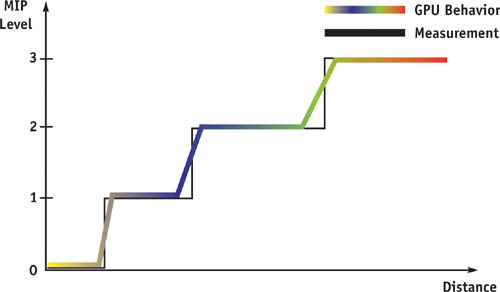
Figure 28-7 Mipmap Level vs. Distance
We can extract more information by changing the calibration texture. As shown in Figure 28-8, we randomize the texel values within a level. In each level, the values are uniformly distributed within one quarter of the texture's total range.
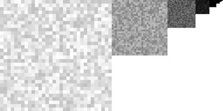
Figure 28-8 Calibration Alpha Values for Velocity
So:
 level0.a ∈ (0.75, 1.00]
level1.a ∈ (0.50, 0.75]
level2.a ∈ (0.25, 0.50]
level3.a ∈ [0.00, 0.25]
Figure 28-9 shows the second level in histogram form.
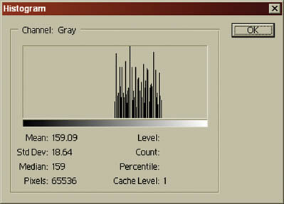
Figure 28-9 The Second Mipmap Level in Histogram Form
Each level is not a different random pattern: they are all magnified, biased versions of the level 3 pattern. The result is that the gradient of values in Figure 28-4 is randomly offset at each texel. Hence, some part of the texture is always straddling our threshold test.
Now as we vary the distance to the measured object, any small change moves some of the measured texels through the threshold tests. The stair-step behavior of Figure 28-7 is smoothed out.
Initially, we thought that the modified calibration texture might permit us to measure the degree to which each mipmap level contributes to the output image. Though this is possible for simple geometry—such as a flat polygon perpendicular to the view direction—the behavior of useful objects is more complex, and we believe that the pixel counts defy analysis. However, this modified calibration texture can provide a measure of how the mipmap levels are changing; information that the mipmap level is increasing, decreasing, or static could be useful.
Derivative Instructions
Using Shader Model ps_2_x or above, the dsx and dsy instructions can be used to directly compute the mip level in the pixel shader (or the HLSL ddx() and ddy() calls could be used). We could dispense with the calibration texture and thus reduce texture bandwidth at the expense of a more complex shader. Retrieving the result from the GPU is still a problem that requires several occlusion queries.
We have not investigated this approach in Leviathan because we support lower pixel shader models with a unified algorithm.
28.3 Sample Results
Useful terrain tends to be flat, and in typical viewpoints, standing on the terrain, polygons will often be seen edge-on. Thus, the required mipmap levels tend to be low. However, any nonflat surfaces will require higher mipmap levels. Figure 28-10 shows a typical example: the same piece of terrain is viewed from two different positions. At viewpoint A, the cliff is visible and requires a higher mipmap level than at viewpoint B, even though both viewpoints are equidistant.
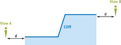
Figure 28-10 Two Views of a Cliff
This orientation dependence is exactly the problem that we set out to solve. So it's not a surprise that mipmap-level measurement can be extremely useful for terrain. We applied the technique to our terrain engine in Leviathan; the results are shown in Table 28-1.
Table 28-1. Memory Savings Measured from the Leviathan Terrain Engine
|
Memory Used (MB) |
Percentage Savings |
|
|
Without Measurement |
4.333 |
0% |
|
0% Threshold |
0.864 |
80% |
|
15% Threshold |
0.538 |
88% |
|
30% Threshold |
0.464 |
89% |
Figure 28-6 shows the visual impact of different threshold values on a piece of terrain. (The view is highly magnified.) The most difference can be seen on the side of a small hill: the hillside is closer to being perpendicular to the view direction, so it displays a higher mipmap level than the surrounding plain. Thus, it "breaks through" the significance threshold first. Increasing the significance threshold produces a gradual degradation in image quality; this is a useful property, and we make our threshold user-configurable, providing a quality-space trade-off.
28.4 Conclusion
The GPU can be used to determine which texture mipmap levels are being used. Our approach relies on the GPU's own texture-mapping hardware to produce this information. This technique has two advantages: First, we do not need to know exactly how the GPU chooses visible mip levels. We have quite deliberately avoided any mathematical discussion of mipmap filtering in this chapter, because it is unnecessary with our approach. The second advantage of using the GPU is that it produces a definitive, accurate answer, taking into account all the complex factors that determine which mip levels get used.
The technique may not be useful in every type of application. For example, in a racing game, the players often proceed linearly around a fixed track; they have limited ability to move in a way that will affect the mipmap levels needed. In that case, the required mipmap levels could be determined statically with less efficient methods.
However, as a developer of massively multiplayer online games, we face novel challenges. Our players have much more control than in many other games, and the result is an environment where texture sizes cannot be predicted in advance. We have successfully applied the technique described in this chapter to produce significant reductions in memory consumption without detectable degradation of the resulting images.
28.5 References
Cebenoyan, Cem. 2004. "Graphics Pipeline Performance." In GPU Gems, edited by Randima Fernando, pp. 473–486. Addison-Wesley.
Climax. 2004. Climax Entertainment Web site. http://www.climaxgroup.com/technology/technology.aspx?ArticleID=152
Williams, Lance. 1983. "Pyramidal Parametrics." Computer Graphics (Proceedings of SIGGRAPH 83) 17(3), pp. 1–11.
Copyright
Many of the designations used by manufacturers and sellers to distinguish their products are claimed as trademarks. Where those designations appear in this book, and Addison-Wesley was aware of a trademark claim, the designations have been printed with initial capital letters or in all capitals.
The authors and publisher have taken care in the preparation of this book, but make no expressed or implied warranty of any kind and assume no responsibility for errors or omissions. No liability is assumed for incidental or consequential damages in connection with or arising out of the use of the information or programs contained herein.
NVIDIA makes no warranty or representation that the techniques described herein are free from any Intellectual Property claims. The reader assumes all risk of any such claims based on his or her use of these techniques.
The publisher offers excellent discounts on this book when ordered in quantity for bulk purchases or special sales, which may include electronic versions and/or custom covers and content particular to your business, training goals, marketing focus, and branding interests. For more information, please contact:
U.S. Corporate and Government Sales
(800) 382-3419
corpsales@pearsontechgroup.com
For sales outside of the U.S., please contact:
International Sales
international@pearsoned.com
Visit Addison-Wesley on the Web: www.awprofessional.com
Library of Congress Cataloging-in-Publication Data
GPU gems 2 : programming techniques for high-performance graphics and general-purpose
computation / edited by Matt Pharr ; Randima Fernando, series editor.
p. cm.
Includes bibliographical references and index.
ISBN 0-321-33559-7 (hardcover : alk. paper)
1. Computer graphics. 2. Real-time programming. I. Pharr, Matt. II. Fernando, Randima.
T385.G688 2005
006.66—dc22
2004030181
GeForce™ and NVIDIA Quadro® are trademarks or registered trademarks of NVIDIA Corporation.
Nalu, Timbury, and Clear Sailing images © 2004 NVIDIA Corporation.
mental images and mental ray are trademarks or registered trademarks of mental images, GmbH.
Copyright © 2005 by NVIDIA Corporation.
All rights reserved. No part of this publication may be reproduced, stored in a retrieval system, or transmitted, in any form, or by any means, electronic, mechanical, photocopying, recording, or otherwise, without the prior consent of the publisher. Printed in the United States of America. Published simultaneously in Canada.
For information on obtaining permission for use of material from this work, please submit a written request to:
Pearson Education, Inc.
Rights and Contracts Department
One Lake Street
Upper Saddle River, NJ 07458
Text printed in the United States on recycled paper at Quebecor World Taunton in Taunton, Massachusetts.
Second printing, April 2005
Dedication
To everyone striving to make today's best computer graphics look primitive tomorrow
- Copyright
- Inside Back Cover
- Inside Front Cover
- Part I: Geometric Complexity
-
- Chapter 1. Toward Photorealism in Virtual Botany
- Chapter 2. Terrain Rendering Using GPU-Based Geometry Clipmaps
- Chapter 3. Inside Geometry Instancing
- Chapter 4. Segment Buffering
- Chapter 5. Optimizing Resource Management with Multistreaming
- Chapter 6. Hardware Occlusion Queries Made Useful
- Chapter 7. Adaptive Tessellation of Subdivision Surfaces with Displacement Mapping
- Chapter 8. Per-Pixel Displacement Mapping with Distance Functions
- Part II: Shading, Lighting, and Shadows
-
- Chapter 9. Deferred Shading in S.T.A.L.K.E.R.
- Chapter 10. Real-Time Computation of Dynamic Irradiance Environment Maps
- Chapter 11. Approximate Bidirectional Texture Functions
- Chapter 12. Tile-Based Texture Mapping
- Chapter 13. Implementing the mental images Phenomena Renderer on the GPU
- Chapter 14. Dynamic Ambient Occlusion and Indirect Lighting
- Chapter 15. Blueprint Rendering and "Sketchy Drawings"
- Chapter 16. Accurate Atmospheric Scattering
- Chapter 17. Efficient Soft-Edged Shadows Using Pixel Shader Branching
- Chapter 18. Using Vertex Texture Displacement for Realistic Water Rendering
- Chapter 19. Generic Refraction Simulation
- Part III: High-Quality Rendering
-
- Chapter 20. Fast Third-Order Texture Filtering
- Chapter 21. High-Quality Antialiased Rasterization
- Chapter 22. Fast Prefiltered Lines
- Chapter 23. Hair Animation and Rendering in the Nalu Demo
- Chapter 24. Using Lookup Tables to Accelerate Color Transformations
- Chapter 25. GPU Image Processing in Apple's Motion
- Chapter 26. Implementing Improved Perlin Noise
- Chapter 27. Advanced High-Quality Filtering
- Chapter 28. Mipmap-Level Measurement
- Part IV: General-Purpose Computation on GPUS: A Primer
-
- Chapter 29. Streaming Architectures and Technology Trends
- Chapter 30. The GeForce 6 Series GPU Architecture
- Chapter 31. Mapping Computational Concepts to GPUs
- Chapter 32. Taking the Plunge into GPU Computing
- Chapter 33. Implementing Efficient Parallel Data Structures on GPUs
- Chapter 34. GPU Flow-Control Idioms
- Chapter 35. GPU Program Optimization
- Chapter 36. Stream Reduction Operations for GPGPU Applications
- Part V: Image-Oriented Computing
-
- Chapter 37. Octree Textures on the GPU
- Chapter 38. High-Quality Global Illumination Rendering Using Rasterization
- Chapter 39. Global Illumination Using Progressive Refinement Radiosity
- Chapter 40. Computer Vision on the GPU
- Chapter 41. Deferred Filtering: Rendering from Difficult Data Formats
- Chapter 42. Conservative Rasterization
- Part VI: Simulation and Numerical Algorithms
-
- Chapter 43. GPU Computing for Protein Structure Prediction
- Chapter 44. A GPU Framework for Solving Systems of Linear Equations
- Chapter 45. Options Pricing on the GPU
- Chapter 46. Improved GPU Sorting
- Chapter 47. Flow Simulation with Complex Boundaries
- Chapter 48. Medical Image Reconstruction with the FFT