
GPU Gems 2
GPU Gems 2 is now available, right here, online. You can purchase a beautifully printed version of this book, and others in the series, at a 30% discount courtesy of InformIT and Addison-Wesley.
The CD content, including demos and content, is available on the web and for download.
Chapter 21. High-Quality Antialiased Rasterization
Dan Wexler
NVIDIA Corporation
Eric Enderton
NVIDIA Corporation
Finely detailed 3D geometry can show significant aliasing artifacts if rendered using native hardware multisampling, because multisampling is currently limited to one-pixel box filtering and low sampling rates. This chapter describes a tiled supersampling technique for rendering images of arbitrary resolution with arbitrarily wide user-defined filters and high sampling rates. The code presented here is used in the Gelato film renderer to produce images of uncompromising quality using the GPU. Figure 21-1 shows an example.
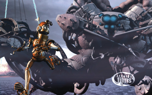
Figure 21-1 An Image Rendered with Gelato
We describe how to break the image into tiles, render each tile at high resolution, then downsample (that is, shrink) each tile to its final resolution, using two-pass separable downsampling with fragment programs constructed on the fly. We present the details involved in proper overlap and padding of the tiles and filters, and we provide code on this book's CD that can be easily incorporated into existing rendering systems without significant modification. The code also includes a number of useful utility libraries for working with the GPU and separable filters.
21.1 Overview
To support large supersampling rates and large final images, we start by breaking the final image into constant-size rectangular tiles (sometimes called buckets), as shown in Figure 21-2. The frame-buffer memory available on the GPU is often insufficient to hold a single frame buffer large enough to render a highly supersampled image prior to downsampling. In addition, you may want to use this limited resource to hold other data required for rendering: textures, vertex buffer objects, and so on. Breaking the image into tiles is also handy if you're rendering a poster-sized image too big to fit in a window. This same technique can be used to "bucket" the geometry (Apodaca and Gritz 1999) by tile to reduce the working set during rendering, although this topic is not directly addressed in this chapter. Because our technique does not restrict the algorithm used to render the tiles, it can easily be combined with multipass algorithms for motion blur, depth of field, transparency, or other effects.
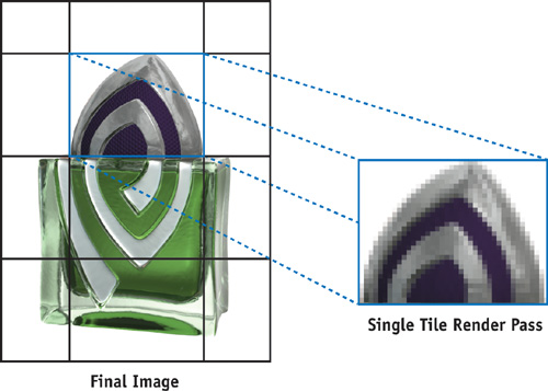
Figure 21-2 Breaking Up an Image into Tiles
We downsample each high-resolution tile on the GPU. This is done using the usual separable convolution (James and O'Rorke 2004), where the first pass filters the rows and the second pass filters the columns, with the added complexity that the output image is smaller than the input image. The fragment program for each pass has the filter values built in as constants (Bjorke 2004). We generate these fragment programs on the fly, based on the selected filter shape, filter width, and supersampling rate.
So the overall algorithm is the following. For each tile of the final image:
- Render the tile into a large off-screen buffer, adjusting the projection matrix to render the 3D geometry at the supersampled resolution using your existing rendering code.
- Downsample the high-resolution tile to a final-resolution tile using a separable filter kernel, by rendering two full-screen quads with custom fragment programs generated on the fly.
- Accumulate the low-resolution tile into the final image, either by reading back the tile data onto the CPU or by using another fragment program to add the tile's contribution into a buffer that accumulates the final result.
We now describe the algorithm from the inside out, beginning with the core downsample-filtering algorithm and then expanding to the enclosing scaffolding. The algorithm will be illustrated using a sample program that renders geometry files (.obj) into an off-screen buffer and saves the result to an image file (.ppm). See Listing 21-1 for a summary of algorithm parameters used in the following discussion.
Example 21-1. Algorithm Parameters Used in Later Listings
int resx = 640;
// final image resolution
int resy = 480;
int ssx = 4;
// supersampling rate
int ssy = 4;
int tx = 32;
// tile size
int ty = 32;
int filterx = 3;
// filter diameter
int filtery = 3;
21.2 Downsampling
Consider one scanline of one tile. The supersampled tile contains (ssx * tx) input pixels (or "samples"), to be downsampled into tx output pixels. Each output pixel is a weighted average of several nearby input samples. The weights are determined by the chosen filter shape, and the number of samples is determined by the chosen filter width and the supersampling rate. (Again, this is just convolution, but with differing input and output resolutions.) Figure 21-3 shows how the filter sits over the input samples for a given output pixel. Note where the center of the filter lies, on both the source and the destination pixels.
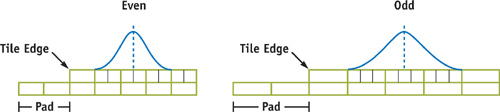
Figure 21-3 Radius 1.5 Gaussian Filter for Even and Odd Supersample Rates
21.2.1 Comparison to Existing Hardware and Software
In current hardware multisampling, each final pixel is a straight average of the samples it covers. This is equivalent to a box (that is, constant) filter of width 1. This works well for many applications, but better antialiasing results from smoother and wider filters. Such filters do a better job of removing spatial frequencies too high to be represented at the final resolution. A 2x2 Gaussian filter is a good default choice, but an examination of current film renderers shows a wide variety of supported filters (sinc, Gaussian, Catmull-Rom, Lanczos, Mitchell, and more) and default filter radii of 2 to 5 pixels. Experiment to see what you like.
Higher supersampling rates also improve antialiasing, especially for small, subpixel 3D geometry, or shaders with subpixel variation. Our algorithm does not entirely escape hardware limitations. The full, supersampled tile resolution (tx * ssx) must be smaller than the largest possible rendering surface supported by the hardware.
In addition, better quality images can be obtained with fewer samples if the samples have well-stratified stochastic locations (Dippé and Wold 1985), as shown in Figure 21-4. Our algorithm uses regular samples and often requires higher sample rates than similar stochastic techniques. This issue is somewhat ameliorated because the hardware tends to perform better when rendering larger objects, which happens when the supersampling rate is increased. Nothing prevents the combination of our technique with hardware multisampling. In fact, the newer generations of hardware support rotated sample grids, which provide better results than standard regular multisampling.
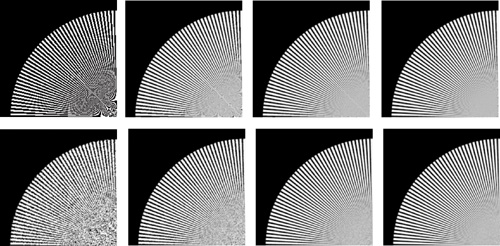
Figure 21-4 Regular vs. Stochastic Sampling
21.2.2 Downsampling on the GPU
To downsample on the GPU, we place the input samples in a row of a texture and render the output pixels as a row of an off-screen buffer. Recall that drawing a rectangle that covers the output pixels will cause the current fragment program to be run for each output pixel (rectangles are like for loops in x and y). We supply a fragment program that computes a weighted sum of some texels, where the weights are based on the filter, and the texel indices depend on the x position of the current output pixel.
Our approach is to automatically generate the fragment program from the filter parameters. The fragment program is straight-line code that includes all filter weights and pixel offsets as numerical constants. This avoids per-pixel evaluation, or even per-pixel texture lookup, of the filter values, and it avoids loop overhead. Although the current generation of fragment program languages supports looping, we have found that unrolling the loop and inlining the constants results in better performance for this case.
Before diving into the detailed formulas, we need to discuss padding.
21.3 Padding
Consider an output pixel within one filter radius of the edge of a tile. Some of the contributing samples for this pixel are in the neighboring tile. To be correct, the final pixel must combine samples from both tiles (four tiles, in the corner regions). To handle this, we pad the size of the downsampling output buffer: the output tile covers not just the pixels covering the input samples, but all pixels to which the input samples contribute. This expands the tile by one filter radius in each direction. (Note: It can be helpful to think of the filter radius as the maximum distance that a sample can "travel" to participate in an output pixel.) The accumulate_tile() function is responsible for summing pixels in the overlap regions to produce the final image.
Considering fractional filter radii, and the fact that some samples fall near the edge of a pixel, the actual padding amount is the following (note the addition of 0.5 to account for the maximal distance that the filter may cover from the edge of a pixel):
int txpad = ceil(filterx / 2.0 + 0.5);
int typad = ceil(filtery / 2.0 + 0.5);
The total size of a downsampled tile is (tx + 2 * txpad) by (ty + 2 * typad).
While downsampling any one tile, "missing" input samples (that is, input samples from outside the tile) are treated as black, because those samples will be accounted for by the neighboring tile. Texture lookup modes are set so that out-of-bounds texture lookups return black. The fragment program can then do the same computation at every pixel, including pixels near the edges.
There is one more padding issue. Pixels near the edges of the final image require input samples from outside the final image. Therefore, we pad the final image size as well, before splitting the image into tiles. Considering fractional radii again, and the fact that the corner pixel already covers 0.5 worth of filter radius, the padding here is the following (note the subtraction of 0.5 to account for the fact that the filter is centered on each pixel):
int resxpad = ceil(filterx / 2.0 - 0.5);
int resypad = ceil(filtery / 2.0 - 0.5);
For example, a 200x200 final image, rendered with a filter width of 2 (radius 1), will require rendering (ssx * 202) by (ssy * 202) samples. See Figure 21-5.
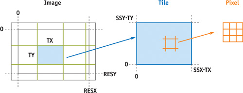
Figure 21-5 Tiling the Image
21.4 Filter Details
There are many details to get right in generating the filter fragment program. The most important detail is that even and odd supersampling rates are subtly different. With even sampling rates, the center of the destination pixel lies on a pixel border in the supersampled image, while odd rates put the pixel center in the center of a source pixel. This is shown in Figure 21-3, which also shows the output tile's padding (on the left side, at least). Samples must be included if the filter overlaps any part of the interval they represent (the ceil() function is useful here). Listing 21-2 shows the pseudocode for runtime generation of the ARBFP1 fragment program. Both Cg and HLSL provide program literalization features that obviate the need for the type of direct assembly-language generation shown here.
Example 21-2. Generating a Downsampling Shader
 ssx = supersampling rate in x
r = ceil(ssx * filterradius)
evenoffset = ssx is even ? 0.5 : 0
pad = ceil(filterradius + 0.5)
for each pixel x in range (-r, r):
weight = normalizedfilter((x + evenoffset) / ssx)
offset = x + evenoffset - pad * ssx
print "MAD coord.xy fragment.position, {$ssx, 1}, {$offset, 1};"
print "TEX sample, coord, texture[0], RECT;"
print "MAD accum, sample, {$weight}, accum;"
Here's a piece of the resulting fragment program.
TEMP coord, sample, accum;
... MAD coord.xy, fragment.position, {4, 1}, {-6.5, 1};
TEX sample, coord, texture[0], RECT;
MAD accum, sample, {0.04509}, accum;
...
This fragment program, run for each pixel in a row of a final-resolution tile, samples pixels from the original image stored as a texture to produce a filtered and shrunken version of the row. Note that the number of samples is the product of the supersampling rate and the filter diameter (which is measured in final image pixels).
21.5 Two-Pass Separable Filtering
With a few x's and y's swapped, the same algorithm produces a fragment program for downsampling columns. We use these two fragment programs to do the usual two-pass separable convolution method: first filter the rows, then take the result as a new input and filter the columns. (Separable filters are a special case of general convolution filters that can be expressed as the product of one-dimensional filters in x and y.)
We start with a supersampled tile of dimensions (ssx * tx) by (ssy * ty). We run the row-downsampling fragment program to produce an intermediate texture that is resolution (tx + 2 * pad) by (ssy * ty). We then run the column-downsampling fragment program on that texture to produce the output tile at the final resolution, (tx + 2 * pad) by (ty + 2 * pad).
21.6 Tiling and Accumulation
Figure 21-5 shows the tiles relative to the final image. Recall that the tiles extend one filter radius beyond the final image. (The tiles, as rendered, do not overlap—never render the same pixel twice. Overlap occurs only after they are downsampled.) Tiles in the last row or column may be mostly empty.
Each tile is rendered in turn at the supersampled resolution. If the projection matrix is set to draw the entire scene at the final resolution resx by resy, we can append some scales and translates to draw a particular tile. For the tile whose origin is (x, y), the final image region [x, x+tx] x [y, y+ty] is mapped to the window [0, ssx*tx] x [0, ssy*ty]:
// Assume cam2ras = the projection matrix for ordinary rendering,
// that is, the transform from camera space to the final image raster.
Matrix4 ras2tile = Matrix4::TranslationMatrix(Vector3(-x, -y, 0)) *
                   Matrix4::ScaleMatrix(ssx, ssy, 1);
Matrix4 cam2tile = cam2ras * ras2tile;
We update the projection matrix using this 2D tile transform and then render the scene once for each tile.
After rendering a supersampled tile, we downsample it to the final resolution using the two-pass filtering method described before. The downsampled tile is then merged (accumulated) into the final image, at its proper position; overlap regions with earlier tiles are summed. The final image may be another OpenGL window or off-screen buffer, in which case accumulation takes place on the GPU, or it may be in main memory, in which case accumulation takes place on the CPU (for example, when the buffer is too large for the GPU).
21.7 The Code
As shown in Listing 21-3, the program begins by creating an off-screen buffer for drawing. Then, using the input parameters, it constructs viewing matrices, image buffers, and filter functions.
Example 21-3. Setting Up for Supersampled Rendering
// Create a drawing surface to render a single supersampled tile
GpuPBuffer pbuffer(resx *ssx, resy *ssy);
GpuCanvas canvas(pbuffer);
// GpuCanvas == OpenGL context
// Create a drawing mode to hold the GPU state vector
GpuDrawmode drawmode;
float fov = 90;
float hither = 0.1;
float yon = 10000;
Matrix4 cam2ras = compute_cam2ras(fov, hither, yon, resx, resy);
// Allocate a 4-channel, fp32, RGBA final output image buffer
size_t nbytes = 4 * resx * resy * sizeof(float);
float *image = (float *)malloc(nbytes);
memset(image, 0, nbytes);
// Create the filter we'll need
Filter2D *filter = Filter2D::MakeFilter("gaussian", filterx, filtery);
// Allocate a 4-channel, fp32, RGBA tile readback buffer
int tilew = downsample.padded_tile_width(tx, *filter);
int tileh = downsample.padded_tile_height(ty, *filter);
float *tile = (float *)malloc(4 * sizeof(float) * tilew * tileh);
The main loop of the program iterates over the output image one tile at a time in row-major order, updating the viewing matrix and calling the render function to render a high-resolution tile. The tile is then downsampled, read back from the GPU, and passed to the accumulate function. Alternatively, the tile could be moved into a texture and the accumulation could happen on the GPU.
21.7.1 The Rendering Loop
Our code uses fp32 precision throughout for the highest possible image quality. It does not use render-to-texture, only because this was not available under Linux at the time it was originally developed. Listing 21-4 shows the rendering loop.
Example 21-4. Rendering All the Tiles
// Pad the final resolution by the filter radius to generate the
// pixels we need to properly filter the edges of the final image
int fx = int(ceil(filter.width() / 2.0 - 0.5));
int fy = int(ceil(filter.height() / 2.0 - 0.5));
// Render all tiles
for (int y = -fy; y < resy + fy; y += ty)
{
  for (int x = fx; x < resx + fx; x += tx)
  {
    // Compute the matrix to render this tile fullscreen
    Matrix4 cam2tile =
        compute_cam2tile(cam2ras, resx, resy, false, x, y, tx, ty);
    drawmode.view(cam2tile, tx * ssx, ty * ssy);
    // Draw the entire scene
    render(drawmode, canvas);
    // Create a texture from the current frame buffer
    GpuTexture fbtex("downsamplefb");
    fbtex.load(canvas, 0, 0, tx * ssx, ty * ssy, GL_FLOAT_RGBA_NV, true, 0,
               true);
    // Downsample the rendered texture and store in a new texture
    downsample.run(fbtex, tx, ty, ssx, ssy, *filter);
    downsample.readback_padded_tile(tx, ty, *filter, tile);
    // Accumulate the resulting texture into the final image
    accumulate_tile(tile, downsample.padded_tile_xorigin(x, *filter),
                    downsample.padded_tile_yorigin(y, *filter), resx, resy,
                    tilew, tileh, image);
  }
}
21.7.2 The Downsample Class
The GpuDownsample class implements the two-pass separable downsample by creating an off-screen drawing surface and generating the custom fragment programs based on the supersample rate and the filter size and type. The class provides functions to enforce the padding required for the tile buffers. The resulting downsampled tile is left on the GPU, and two functions are provided to read back the data to a CPU buffer or convert the drawing surface into a texture (another place where we could be using render-to-texture).
The main downsample function appears in Listing 21-5.
Example 21-5. Main Function for Two-Pass Downsampling
void GpuDownsample::run(GpuTexture &fbtex, int tx, int ty, int ssx, int ssy,
                        Filter2D &filter)
{
  // compute the padded resolution for the intermediary passes
  int dstw = tx + 2 * filter.width();
  int dsth = ty + 2 * filter.height();
  // compute the resolution of the source texture
  int srcw = tx * ssx;
  int srch = ty * ssy;
  // create a new pbuffer and canvas if needed
  if (pbuffer == NULL || pbuffer->w() < dstw || pbuffer->h() < max(srch, dsth))
  {
    delete canvas;
    delete pbuffer;
    pbuffer = new GpuPBuffer(dstw, max(srch, dsth));
    canvas = new GpuCanvas(*pbuffer);
  }
  canvas->clear(0.2, 0, 0.2); // for debugging only
  // only create a new program if we need to
  if (xpass == NULL || ssx != last_ssx || ssy != last_ssy)
  {
    last_ssx = ssx;
    last_ssy = ssy;
    delete ypass;
    delete xpass;
    // generate fragment programs for each pass
    const char *code;
    code = generate_xory_pass_fp10(filter, ssx, ssy, true);
    xpass = new GpuFragmentProgram("xpass", code);
    free((char *)code);
    code = generate_xory_pass_fp10(filter, ssx, ssy, false);
    ypass = new GpuFragmentProgram("ypass", code);
    free((char *)code);
  }
  // dimensions of destination image in each pass
  int pw = dstw;
  int ph = srch;
  GpuDrawmode drawmode;
  drawmode.texture(0, fbtex);
  // set src in tex0
  drawmode.fragment_program(xpass);
  // set fragment prog
  drawmode.view(pw, ph);
  // set 2D pixel view
  GpuPrimitive rect0(0, pw, 0, ph);
  // fullscreen rect
  rect0.render(drawmode, *canvas);
  // compute first pass
  fbtex.load(*canvas, 0, 0, pw, ph, GL_FLOAT_RGBA_NV, true, 0, true);
  ph = dsth;
  // second pass height
  drawmode.view(pw, ph);
  // dest 2D view
  drawmode.fragment_program(ypass);
  // set fragment prog
  GpuPrimitive rect1(0, pw, 0, ph);
  // fullscreen rect
  rect1.render(drawmode, *canvas);
  // second pass
21.7.3 Implementation Details
Our code uses a number of utilities libraries that are included in the sample code on this book's CD. The GPU library is a high-level interface to OpenGL that provides routines for constructing windows, off-screen buffers, textures, and vertex and fragment programs. It also provides optimized vertex buffer object (VBO) primitive drawing routines that work under both Windows and Linux. Its drawmode objects encapsulate OpenGL states, minimizing state changes and making debugging much easier. The library is fully thread-safe and supports drawing to multiple buffers.
The code included on the CD also contains low-level vector and matrix functions (on the CPU), along with a platform-independent thread-management library. The Filter library provides a set of commonly used sampling filters.
21.8 Conclusion
Film, video, and print often require better antialiasing than what current hardware natively provides. The GPU-based technique described here achieves the same image quality as software renderers, while placing almost no limitations on the basic scene rendering method used. The sample code provided is easy to graft onto your existing rendering program (we hope), letting you render beautifully antialiased frames.
This technique works around filter-quality limitations by using fragment programs, and it works around buffer-size limitations by using tiling. The filtering step makes quite effective use of the GPU's parallel floating-point power.
21.9 References
Apodaca, Anthony A., and Larry Gritz, eds. 1999. Advanced RenderMan: Creating CGI for Motion Pictures. Morgan Kaufmann.
Bjorke, Kevin. 2004. "High-Quality Filtering." In GPU Gems, edited by Randima Fernando, pp. 391–415. Addison-Wesley.
Dippé, Mark A. Z., and Erling H. Wold. 1985. "Antialiasing through Stochastic Sampling." In Computer Graphics (Proceedings of SIGGRAPH 85) 19(3), pp. 69–78.
James, Greg, and John O'Rorke. 2004. "Real-Time Glow." In GPU Gems, edited by Randima Fernando, pp. 343–362. Addison-Wesley.
Copyright
Many of the designations used by manufacturers and sellers to distinguish their products are claimed as trademarks. Where those designations appear in this book, and Addison-Wesley was aware of a trademark claim, the designations have been printed with initial capital letters or in all capitals.
The authors and publisher have taken care in the preparation of this book, but make no expressed or implied warranty of any kind and assume no responsibility for errors or omissions. No liability is assumed for incidental or consequential damages in connection with or arising out of the use of the information or programs contained herein.
NVIDIA makes no warranty or representation that the techniques described herein are free from any Intellectual Property claims. The reader assumes all risk of any such claims based on his or her use of these techniques.
The publisher offers excellent discounts on this book when ordered in quantity for bulk purchases or special sales, which may include electronic versions and/or custom covers and content particular to your business, training goals, marketing focus, and branding interests. For more information, please contact:
U.S. Corporate and Government Sales
(800) 382-3419
corpsales@pearsontechgroup.com
For sales outside of the U.S., please contact:
International Sales
international@pearsoned.com
Visit Addison-Wesley on the Web: www.awprofessional.com
Library of Congress Cataloging-in-Publication Data
GPU gems 2 : programming techniques for high-performance graphics and general-purpose
computation / edited by Matt Pharr ; Randima Fernando, series editor.
p. cm.
Includes bibliographical references and index.
ISBN 0-321-33559-7 (hardcover : alk. paper)
1. Computer graphics. 2. Real-time programming. I. Pharr, Matt. II. Fernando, Randima.
T385.G688 2005
006.66—dc22
2004030181
GeForce™ and NVIDIA Quadro® are trademarks or registered trademarks of NVIDIA Corporation.
Nalu, Timbury, and Clear Sailing images © 2004 NVIDIA Corporation.
mental images and mental ray are trademarks or registered trademarks of mental images, GmbH.
Copyright © 2005 by NVIDIA Corporation.
All rights reserved. No part of this publication may be reproduced, stored in a retrieval system, or transmitted, in any form, or by any means, electronic, mechanical, photocopying, recording, or otherwise, without the prior consent of the publisher. Printed in the United States of America. Published simultaneously in Canada.
For information on obtaining permission for use of material from this work, please submit a written request to:
Pearson Education, Inc.
Rights and Contracts Department
One Lake Street
Upper Saddle River, NJ 07458
Text printed in the United States on recycled paper at Quebecor World Taunton in Taunton, Massachusetts.
Second printing, April 2005
Dedication
To everyone striving to make today's best computer graphics look primitive tomorrow
- Copyright
- Inside Back Cover
- Inside Front Cover
- Part I: Geometric Complexity
-
- Chapter 1. Toward Photorealism in Virtual Botany
- Chapter 2. Terrain Rendering Using GPU-Based Geometry Clipmaps
- Chapter 3. Inside Geometry Instancing
- Chapter 4. Segment Buffering
- Chapter 5. Optimizing Resource Management with Multistreaming
- Chapter 6. Hardware Occlusion Queries Made Useful
- Chapter 7. Adaptive Tessellation of Subdivision Surfaces with Displacement Mapping
- Chapter 8. Per-Pixel Displacement Mapping with Distance Functions
- Part II: Shading, Lighting, and Shadows
-
- Chapter 9. Deferred Shading in S.T.A.L.K.E.R.
- Chapter 10. Real-Time Computation of Dynamic Irradiance Environment Maps
- Chapter 11. Approximate Bidirectional Texture Functions
- Chapter 12. Tile-Based Texture Mapping
- Chapter 13. Implementing the mental images Phenomena Renderer on the GPU
- Chapter 14. Dynamic Ambient Occlusion and Indirect Lighting
- Chapter 15. Blueprint Rendering and "Sketchy Drawings"
- Chapter 16. Accurate Atmospheric Scattering
- Chapter 17. Efficient Soft-Edged Shadows Using Pixel Shader Branching
- Chapter 18. Using Vertex Texture Displacement for Realistic Water Rendering
- Chapter 19. Generic Refraction Simulation
- Part III: High-Quality Rendering
-
- Chapter 20. Fast Third-Order Texture Filtering
- Chapter 21. High-Quality Antialiased Rasterization
- Chapter 22. Fast Prefiltered Lines
- Chapter 23. Hair Animation and Rendering in the Nalu Demo
- Chapter 24. Using Lookup Tables to Accelerate Color Transformations
- Chapter 25. GPU Image Processing in Apple's Motion
- Chapter 26. Implementing Improved Perlin Noise
- Chapter 27. Advanced High-Quality Filtering
- Chapter 28. Mipmap-Level Measurement
- Part IV: General-Purpose Computation on GPUS: A Primer
-
- Chapter 29. Streaming Architectures and Technology Trends
- Chapter 30. The GeForce 6 Series GPU Architecture
- Chapter 31. Mapping Computational Concepts to GPUs
- Chapter 32. Taking the Plunge into GPU Computing
- Chapter 33. Implementing Efficient Parallel Data Structures on GPUs
- Chapter 34. GPU Flow-Control Idioms
- Chapter 35. GPU Program Optimization
- Chapter 36. Stream Reduction Operations for GPGPU Applications
- Part V: Image-Oriented Computing
-
- Chapter 37. Octree Textures on the GPU
- Chapter 38. High-Quality Global Illumination Rendering Using Rasterization
- Chapter 39. Global Illumination Using Progressive Refinement Radiosity
- Chapter 40. Computer Vision on the GPU
- Chapter 41. Deferred Filtering: Rendering from Difficult Data Formats
- Chapter 42. Conservative Rasterization
- Part VI: Simulation and Numerical Algorithms
-
- Chapter 43. GPU Computing for Protein Structure Prediction
- Chapter 44. A GPU Framework for Solving Systems of Linear Equations
- Chapter 45. Options Pricing on the GPU
- Chapter 46. Improved GPU Sorting
- Chapter 47. Flow Simulation with Complex Boundaries
- Chapter 48. Medical Image Reconstruction with the FFT