
GPU Gems 2
GPU Gems 2 is now available, right here, online. You can purchase a beautifully printed version of this book, and others in the series, at a 30% discount courtesy of InformIT and Addison-Wesley.
The CD content, including demos and content, is available on the web and for download.
Chapter 14. Dynamic Ambient Occlusion and Indirect Lighting
Michael Bunnell
NVIDIA Corporation
In this chapter we describe a new technique for computing diffuse light transfer and show how it can be used to compute global illumination for animated scenes. Our technique is efficient enough when implemented on a fast GPU to calculate ambient occlusion and indirect lighting data on the fly for each rendered frame. It does not have the limitations of precomputed radiance transfer (PRT) or precomputed ambient occlusion techniques, which are limited to rigid objects that do not move relative to one another (Sloan 2002). Figure 14-1 illustrates how ambient occlusion and indirect lighting enhance environment lighting.
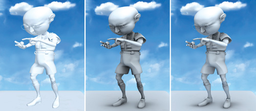
Figure 14-1 Adding Realism with Ambient Occlusion and Indirect Lighting
Our technique works by treating polygon meshes as a set of surface elements that can emit, transmit, or reflect light and that can shadow each other. This method is so efficient because it works without calculating the visibility of one element to another. Instead, it uses a much simpler and faster technique based on approximate shadowing to account for occluding (blocking) geometry.
14.1 Surface Elements
The first step in our algorithm is to convert the polygonal data to surface elements to make it easy to calculate how much one part of a surface shadows or illuminates another. Figure 14-2 illustrates the basic concept. We define a surface element as an oriented disk with a position, normal, and area. An element has a front face and a back face. Light is emitted and reflected from the front-facing side. Light is transmitted and shadows are cast from the back. We create one element per vertex of the mesh. Assuming that the vertices are defined with a position and normal already, we just need to calculate the area of each element. We calculate the area at a vertex as the sum of one-third of the area of the triangles that share the vertex (or one-fourth of the area for quads). Heron's formula for the area of a triangle with sides of length a, b, and c is:
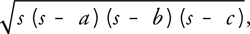
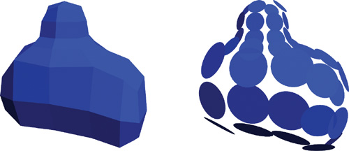
Figure 14-2 Converting a Polygonal Mesh to Elements
where s is half the perimeter of the triangle: (a + b + c)/2.
We store element data (position, normal, and area) in texture maps because we will be using a fragment program (that is, a pixel shader) to do all the ambient occlusion calculations. Assuming that vertex positions and normals will change for each frame, we need to be able to change the values in the texture map quickly. One option is to keep vertex data in a texture map from the start and to do all the animation and transformation from object space to eye (or world) space with fragment programs instead of vertex programs. We can use render-to-vertex-array to create the array of vertices to be sent down the regular pipeline, and then use a simple pass-through vertex shader. Another, less efficient option is to do the animation and transformation on the CPU and load a texture with the vertex data each frame.
14.2 Ambient Occlusion
Ambient occlusion is a useful technique for adding shadowing to diffuse objects lit with environment lighting. Without shadows, diffuse objects lit from many directions look flat and unrealistic. Ambient occlusion provides soft shadows by darkening surfaces that are partially visible to the environment. It involves calculating the accessibility value, which is the percentage of the hemisphere above each surface point not occluded by geometry (Landis 2002). In addition to accessibility, it is also useful to calculate the direction of least occlusion, commonly known as the bent normal. The bent normal is used in place of the regular normal when shading the surface for more accurate environment lighting.
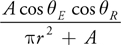
We can calculate the accessibility value at each element as 1 minus the amount by which all the other elements shadow the element. We refer to the element that is shadowed as the receiver and to the element that casts the shadow as the emitter. We use an approximation based on the solid angle of an oriented disk to calculate the amount by which an emitter element shadows a receiver element. Given that A is the area of the emitter, the amount of shadow can be approximated by:
Equation 14-1 Shadow Approximation
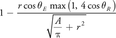
As illustrated in Figure 14-3, E is the angle between the emitter's normal and the vector from the emitter to the receiver. R is the corresponding angle for the receiver element. The max(1, 4 x cos R ) term is added to the disk solid angle formula to ignore emitters that do not lie in the hemisphere above the receiver without causing rendering artifacts for elements that lie near the horizon.
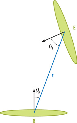
Figure 14-3 The Relationship Between Receiver and Emitter Elements
Here is the fragment program function to approximate the element-to-element occlusion:
float ElementShadow(float3 v, float rSquared, float3 receiverNormal,
                    float3 emitterNormal, float emitterArea)
{
  // we assume that emitterArea has already been divided by PI
  return (1 - rsqrt(emitterArea / rSquared + 1)) *
         saturate(dot(emitterNormal, v)) * saturate(4 * dot(receiverNormal, v));
}
14.2.1 The Multipass Shadowing Algorithm
We calculate the accessibility values in two passes. In the first pass, we approximate the accessibility for each element by summing the fraction of the hemisphere subtended by every other element and subtracting the result from 1. After the first pass, some elements will generally be too dark because other elements that are in shadow are themselves casting shadows. So we use a second pass to do the same calculation, but this time we multiply each form factor by the emitter element's accessibility from the last pass. The effect is that elements that are in shadow will cast fewer shadows on other elements, as illustrated in Figure 14-4. After the second pass, we have removed any double shadowing. However, surfaces that are triple shadowed or more will end up being too light. We can use more passes to get a better approximation, but we can approximate the same answer by using a weighted average of the combined results of the first and second passes. Figure 14-5 shows the results after each pass, as well as a ray-traced solution for comparison. The bent normal calculation is done during the second pass. We compute the bent normal by first multiplying the normalized vector between elements and the form factor. Then we subtract this result from the original element normal.
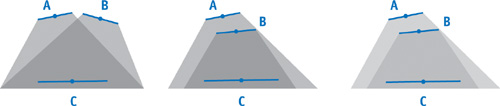
Figure 14-4 Correcting for Occlusion by Overlapping Objects
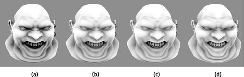
Figure 14-5 Comparing Models Rendered with Our Technique to Reference Images
We calculate the occlusion result by rendering a single quad (or two triangles) so that one pixel is rendered for each surface element. The shader calculates the amount of shadow received at each element and writes it as the alpha component of the color of the pixel. The results are rendered to a texture map so the second pass can be performed with another render. In this pass, the bent normal is calculated and written as the RGB value of the color with a new shadow value that is written in the alpha component.
14.2.2 Improving Performance
Even though the element-to-element shadow calculation is very fast (a GeForce 6800 can do 150 million of these calculations per second), we need to improve our algorithm to work on more than a couple of thousand elements in real time. We can reduce the amount of work by using simplified geometry for distant surfaces. This approach works well for diffuse lighting environments because the shadows are so soft that those cast by details in distant geometry are not visible. Fortunately, because we do not use the polygons themselves in our technique, we can create surface elements to represent simplified geometry without needing to create alternate polygonal models. We simply group elements whose vertices are neighbors in the original mesh and represent them with a single, larger element. We can do the same thing with the larger elements, creating fewer and even larger elements, forming a hierarchy. Now instead of traversing every single element for each pixel we render, we traverse the hierarchy of elements. If the receiver element is far enough away from the emitter—say, four times the radius of the emitter—we use it for our calculation. Only if the receiver is close to an emitter do we need to traverse its children (if it has any). See Figure 14-6. By traversing a hierarchy in this way, we can improve the performance of our algorithm from O(n 2) to O(n log n) in practice. The chart in Figure 14-7 shows that the performance per vertex stays consistent as the number of vertices in the hierarchy increases.
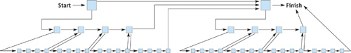
Figure 14-6 Hierarchical Elements
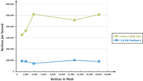
Figure 14-7 Ambient Occlusion Shader Performance for Meshes of Different Densities
We calculate a parent element's data using its direct descendants in the hierarchy. We calculate the position and normal of a parent element by averaging the positions and normals of its children. We calculate its area as the sum of its children's areas. We can use a shader for these calculations by making one pass of the shader for each level in the hierarchy, propagating the values from the leaf nodes up. We can then use the same technique to average the results of an occlusion pass that are needed for a following pass or simply treat parent nodes the same as children and avoid the averaging step. It is worth noting that the area of most animated elements varies little, if at all, even for nonrigid objects; therefore, the area does not have to be recalculated for each frame.
The ambient occlusion fragment shader appears in Listing 14-1.
Example 14-1. Ambient Occlusion Shader
float4 AmbientOcclusion(float4 position
                        : WPOS, float4 normOffset
                        : TEX1, uniform samplerRECT lastResultMap
                        : TEXUNIT0, uniform samplerRECT positionMap
                        : TEXUNIT1, uniform samplerRECT elementNormalMap
                        : TEXUNIT2, uniform samplerRECT indexMap
                        : TEXUNIT3)
    : COL
{
  float eArea;
  // emitter area
  float4 ePosition; // emitter position
  float4 eNormal;
  // emitter normal
  float3 rPosition = texRECT(positionMap, position.xy).xyz;
  float3 rNormal = texRECT(elementNormalMap, position.xy).xyz;
  float3 v;
  // vector from receiver to emitter
  float total = 0;
  // used to calculate accessibility
  float4 eIndex = float2(0.5, 0.5); // index of current emitter
  float3 bentNormal = rNormal;
  // initialize with receiver normal
  float value;
  float d2;
  // distance from receiver to emitter squared
  while (emitterIndex.x != 0)
  { // while not finished traversal
    ePosition = texRECT(positionMap, emitterIndex.xy);
    eNormal = texRECT(elementNormalMap, emitterIndex.xy);
    eArea = emitterNormal.w;
    eIndex = texRECT(indexMap, emitterIndex.xy); // get next index
    v = ePosition.xyz - rPosition;
    // vector to emitter
    d2 = dot(v, v) + 1e - 16;
    // calc distance squared, avoid 0
    // is receiver close to parent element?
    if (d2 < -4 * emitterArea)
    {
      // (parents have negative area)
      eIndex.xy = eIndex.zw;
      // go down hierarchy
      emitterArea = 0;
      // ignore this element
    }
    v *= rsqrt(d2);
    // normalize v
    value = SolidAngle(v, d2, rNormal, eNormal.xyz, abs(eArea)) *
            texRECT(resultMap, position.xy).w; // modulate by last result
    bentNormal -= value * v;
    // update bent normal
    total += value;
  }
  if (!lastPass)
    // only need bent normal for last pass
    return saturate(1 - total); // return accessibility only
  else
    return float4(normalize(bentNormal), 1 Ð total);
}
14.3 Indirect Lighting and Area Lights
We can add an extra level of realism to rendered images by adding indirect lighting caused by light reflecting off diffuse surfaces (Tabellion 2004). We can add a single bounce of indirect light using a slight variation of the ambient occlusion shader. We replace the solid angle function with a disk-to-disk radiance transfer function. We use one pass of the shader to transfer the reflected or emitted light and two passes to shadow the light.
For indirect lighting, first we need to calculate the amount of light to reflect off the front face of each surface element. If the reflected light comes from environment lighting, then we compute the ambient occlusion data first and use it to compute the environment light that reaches each vertex. If we are using direct lighting from point or directional lights, we compute the light at each element just as if we are shading the surface, including shadow mapping. We can also do both environment lighting and direct lighting and sum the two results. We then multiply the light values by the color of the surface element, so that red surfaces reflect red, yellow surfaces reflect yellow, and so on. Area lights are handled just like light-reflective diffuse surfaces except that they are initialized with a light value to emit.
Here is the fragment program function to calculate element-to-element radiance transfer:
float FormFactor(float3 v, float d2, float3 receiverNormal,
                 float3 emitterNormal, float emitterArea)
{
  // assume that emitterArea has been divided by PI
  return emitterArea * saturate(dot(emitterNormal, v)) *
         saturate(dot(receiverNormal, v)) / (d2 + emitterArea);
}
Equation 14-2 Disk-to-Disk Form Factor Approximation
We calculate the amount of light transferred from one surface element to another using the geometric term of the disk-to-disk form factor given in Equation 14-2. We leave off the visibility factor, which takes into account blocking (occluding) geometry. Instead we use a shadowing technique like the one we used for calculating ambient occlusion—only this time we use the same form factor that we used to transfer the light. Also, we multiply the shadowing element's form factor by the three-component light value instead of a single-component accessibility value.
We now run one pass of our radiance-transfer shader to calculate the maximum amount of reflected or emitted light that can reach any element. Then we run a shadow pass that subtracts from the total light at each element based on how much light reaches the shadowing elements. Just as with ambient occlusion, we can run another pass to improve the lighting by removing double shadowing. Figure 14-8 shows a scene lit with direct lighting plus one and two bounces of indirect lighting.
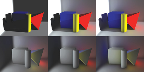
Figure 14-8 Combining Direct and Indirect Lighting
14.4 Conclusion
Global illumination techniques such as ambient occlusion and indirect lighting greatly enhance the quality of rendered diffuse surfaces. We have presented a new technique for calculating light transfer to and from diffuse surfaces using the GPU. This technique is suitable for implementing various global illumination effects in dynamic scenes with deformable geometry.
14.5 References
Landis, Hayden. 2002. "Production-Ready Global Illumination." Course 16 notes, SIGGRAPH 2002.
Pharr, Matt, and Simon Green. 2004. "Ambient Occlusion." In GPU Gems, edited by Randima Fernando, pp. 279–292. Addison-Wesley.
Sloan, Peter-Pike, Jan Kautz, and John Snyder. 2002. "Precomputed Radiance Transfer for Real-Time Rendering in Dynamic, Low-Frequency Lighting Environments." ACM Transactions on Graphics (Proceedings of SIGGRAPH 2002) 21(3), pp. 527–536.
Tabellion, Eric, and Arnauld Lamorlette. 2004. "An Approximate Global Illumination System for Computer Generated Films." ACM Transactions on Graphics (Proceedings of SIGGRAPH 2004) 23(3), pp. 469–476.
Copyright
Many of the designations used by manufacturers and sellers to distinguish their products are claimed as trademarks. Where those designations appear in this book, and Addison-Wesley was aware of a trademark claim, the designations have been printed with initial capital letters or in all capitals.
The authors and publisher have taken care in the preparation of this book, but make no expressed or implied warranty of any kind and assume no responsibility for errors or omissions. No liability is assumed for incidental or consequential damages in connection with or arising out of the use of the information or programs contained herein.
NVIDIA makes no warranty or representation that the techniques described herein are free from any Intellectual Property claims. The reader assumes all risk of any such claims based on his or her use of these techniques.
The publisher offers excellent discounts on this book when ordered in quantity for bulk purchases or special sales, which may include electronic versions and/or custom covers and content particular to your business, training goals, marketing focus, and branding interests. For more information, please contact:
U.S. Corporate and Government Sales
(800) 382-3419
corpsales@pearsontechgroup.com
For sales outside of the U.S., please contact:
International Sales
international@pearsoned.com
Visit Addison-Wesley on the Web: www.awprofessional.com
Library of Congress Cataloging-in-Publication Data
GPU gems 2 : programming techniques for high-performance graphics and general-purpose
computation / edited by Matt Pharr ; Randima Fernando, series editor.
p. cm.
Includes bibliographical references and index.
ISBN 0-321-33559-7 (hardcover : alk. paper)
1. Computer graphics. 2. Real-time programming. I. Pharr, Matt. II. Fernando, Randima.
T385.G688 2005
006.66—dc22
2004030181
GeForce™ and NVIDIA Quadro® are trademarks or registered trademarks of NVIDIA Corporation.
Nalu, Timbury, and Clear Sailing images © 2004 NVIDIA Corporation.
mental images and mental ray are trademarks or registered trademarks of mental images, GmbH.
Copyright © 2005 by NVIDIA Corporation.
All rights reserved. No part of this publication may be reproduced, stored in a retrieval system, or transmitted, in any form, or by any means, electronic, mechanical, photocopying, recording, or otherwise, without the prior consent of the publisher. Printed in the United States of America. Published simultaneously in Canada.
For information on obtaining permission for use of material from this work, please submit a written request to:
Pearson Education, Inc.
Rights and Contracts Department
One Lake Street
Upper Saddle River, NJ 07458
Text printed in the United States on recycled paper at Quebecor World Taunton in Taunton, Massachusetts.
Second printing, April 2005
Dedication
To everyone striving to make today's best computer graphics look primitive tomorrow
- Copyright
- Inside Back Cover
- Inside Front Cover
- Part I: Geometric Complexity
-
- Chapter 1. Toward Photorealism in Virtual Botany
- Chapter 2. Terrain Rendering Using GPU-Based Geometry Clipmaps
- Chapter 3. Inside Geometry Instancing
- Chapter 4. Segment Buffering
- Chapter 5. Optimizing Resource Management with Multistreaming
- Chapter 6. Hardware Occlusion Queries Made Useful
- Chapter 7. Adaptive Tessellation of Subdivision Surfaces with Displacement Mapping
- Chapter 8. Per-Pixel Displacement Mapping with Distance Functions
- Part II: Shading, Lighting, and Shadows
-
- Chapter 9. Deferred Shading in S.T.A.L.K.E.R.
- Chapter 10. Real-Time Computation of Dynamic Irradiance Environment Maps
- Chapter 11. Approximate Bidirectional Texture Functions
- Chapter 12. Tile-Based Texture Mapping
- Chapter 13. Implementing the mental images Phenomena Renderer on the GPU
- Chapter 14. Dynamic Ambient Occlusion and Indirect Lighting
- Chapter 15. Blueprint Rendering and "Sketchy Drawings"
- Chapter 16. Accurate Atmospheric Scattering
- Chapter 17. Efficient Soft-Edged Shadows Using Pixel Shader Branching
- Chapter 18. Using Vertex Texture Displacement for Realistic Water Rendering
- Chapter 19. Generic Refraction Simulation
- Part III: High-Quality Rendering
-
- Chapter 20. Fast Third-Order Texture Filtering
- Chapter 21. High-Quality Antialiased Rasterization
- Chapter 22. Fast Prefiltered Lines
- Chapter 23. Hair Animation and Rendering in the Nalu Demo
- Chapter 24. Using Lookup Tables to Accelerate Color Transformations
- Chapter 25. GPU Image Processing in Apple's Motion
- Chapter 26. Implementing Improved Perlin Noise
- Chapter 27. Advanced High-Quality Filtering
- Chapter 28. Mipmap-Level Measurement
- Part IV: General-Purpose Computation on GPUS: A Primer
-
- Chapter 29. Streaming Architectures and Technology Trends
- Chapter 30. The GeForce 6 Series GPU Architecture
- Chapter 31. Mapping Computational Concepts to GPUs
- Chapter 32. Taking the Plunge into GPU Computing
- Chapter 33. Implementing Efficient Parallel Data Structures on GPUs
- Chapter 34. GPU Flow-Control Idioms
- Chapter 35. GPU Program Optimization
- Chapter 36. Stream Reduction Operations for GPGPU Applications
- Part V: Image-Oriented Computing
-
- Chapter 37. Octree Textures on the GPU
- Chapter 38. High-Quality Global Illumination Rendering Using Rasterization
- Chapter 39. Global Illumination Using Progressive Refinement Radiosity
- Chapter 40. Computer Vision on the GPU
- Chapter 41. Deferred Filtering: Rendering from Difficult Data Formats
- Chapter 42. Conservative Rasterization
- Part VI: Simulation and Numerical Algorithms
-
- Chapter 43. GPU Computing for Protein Structure Prediction
- Chapter 44. A GPU Framework for Solving Systems of Linear Equations
- Chapter 45. Options Pricing on the GPU
- Chapter 46. Improved GPU Sorting
- Chapter 47. Flow Simulation with Complex Boundaries
- Chapter 48. Medical Image Reconstruction with the FFT