
GPU Gems 2
GPU Gems 2 is now available, right here, online. You can purchase a beautifully printed version of this book, and others in the series, at a 30% discount courtesy of InformIT and Addison-Wesley.
The CD content, including demos and content, is available on the web and for download.
Chapter 18. Using Vertex Texture Displacement for Realistic Water Rendering
Yuri Kryachko
1C:Maddox Games
Water surfaces are common in computer graphics, especially in games. They are a critical element that can significantly improve the level of realism in a scene. But depicting them realistically is a hard problem, because of the high visual complexity present in the motion of water surfaces, as well as in the way light interacts with water. This chapter describes techniques developed for rendering realistic depictions of the ocean for the game Pacific Fighters.
Modern graphics hardware provides a number of useful features with DirectX Shader Model 3.0 that can be used to aid the rendering of water surfaces. This chapter will discuss how one of these features, vertex texturing, can be used to increase the realism of rendered water surfaces. Figure 18-1 shows some sample results. In addition, we also use branching in order to improve the performance of our vertex programs.
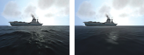
Figure 18-1 The Benefits of Displacement Mapping
18.1 Water Models
For water animation and rendering, a number of methods have been developed. The most remarkable and realistic-looking ones are those based on fluid dynamics and Fast Fourier Transforms (FFTs)(such as Tessendorf 2001). These methods provide very realistic results, but unfortunately they require substantial amounts of computation, making them inappropriate for interactive applications.
At the other extreme, most games currently use very simple water models, most of which employ normal maps to create visual details. Unfortunately, these approaches cannot provide enough realism and do not faithfully reproduce waves on the surface.
We seek a technique that combines the speed of simple normal-mapped water-rendering methods with the visual quality of FFT-like approaches.
18.2 Implementation
Our implementation builds upon rendering algorithms that employ normal maps for lighting calculations. Because normal maps faithfully reproduce fine detail in high-frequency waves, we use them for our lighting calculations. However, in addition, we perturb the water mesh geometrically with lower-frequency waves with large amplitude.
18.2.1 Water Surface Model
Our model of a water surface is based on the superposition of several height maps, tiled in both space and time. Each texture represents one "harmonic" or "octave" of the spectrum, and the textures are added together as in Fourier synthesis. These textures are called height maps because each value represents the elevation of the corresponding point above the horizontal plane.
Height maps are great for artists: creating them is as simple as painting a grayscale image. See Figure 18-2. With height maps, artists can easily control the parameters of water animation down to individual waves by just painting their shapes. Height maps also work well as vertex textures: using them to displace vertex positions vertically is trivial.
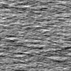
Figure 18-2 A Height Map Used for Water Displacement
By combining several height maps with different spatial and time scales, we can achieve complex and visually intricate animations:
The coefficients A and B and the number of terms under the sum are chosen heuristically to achieve the most aesthetically pleasing results while minimizing repeating-pattern artifacts. In Pacific Fighters, we sum four height maps for lighting calculations, and two of them with the largest scale are used for displacement mapping. This is sufficient for simulating moving ocean surfaces at scales from 10 cm up to 40 km.
18.2.2 Implementation Details
All of the computations we need to perform can be classified into two groups: geometric displacement computations and lighting computations. Because our water surface is finely tessellated, it is reasonable to perform lighting calculations at the fragment program level, offloading the displacement mapping to the vertex stage. Also, performing lighting calculations at the vertex stage can create visual artifacts, especially in the distance.
At the time of writing, the only hardware capable of doing vertex texturing were GeForce 6 Series GPUs and the latest NVIDIA Quadro FX GPUs. The vertex texture implementation on this hardware has certain restrictions; in particular, vertex textures must be 32-bit-per-component textures, floating point, and they can't use any filtering mode except nearest filtering. Nevertheless, they proved to be very useful for the techniques described in this chapter.
18.2.3 Sampling Height Maps
Our implementation samples the height maps per vertex and computes the resulting displacement value in the vertex program. For sampling, we use a radial grid, centered at the camera position. This grid is tessellated in such a way that it provides more detail closer to the viewer, as shown in Figure 18-3.
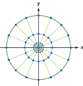
Figure 18-3 Radial Grid for Sampling Vertex Textures
The following equations show how the vertex positions for the radial grid are computed.
|
r = a 0 + a 1 i 4 |
|
xi,j = r cos (2j/M) |
|
yi,j = r sin (2j/M), |
where i = [0..N - 1], j = [0..M - 1]. We choose a 0, a 1 so that
|
r 0 = a 0 = 10 cm |
|
r N-1 = a 0 + a 1 (N-1)4 = 40 km. |
With this approach, we naturally get distance-based tessellation, which provides a simple level-of-detail (LOD) scheme. Other approaches, such as the ROAM or SOAR terrain-rendering algorithms, could be used here, but they require a significant amount of work on the CPU side, which would eliminate all the benefits of using vertex textures. See Chapter 2 of this book, "Terrain Rendering Using GPU-Based Geometry Clipmaps," for another approach to rendering height fields on the GPU with adaptive tessellation.
Listing 18-1 shows the simple vertex shader that implements sampling from a single height map with a radial grid.
Example 18-1. Vertex Shader for Sampling from a Height Map Using the Radial Grid Geometry
float4 main(float4 position
            : POSITION, uniform sampler2D tex0, uniform float4x4 ModelViewProj,
              uniform float4 DMParameters, // displacement map parameters
              uniform float4 VOfs)
    : POSITION
{
  // Read vertex packed as (cos(), sin(), j)
  float4 INP = position;
  // Transform to radial grid vertex
  INP.xy = INP.xy * (pow(INP.z, 4) * VOfs.z);
  // Find displacement map texture coordinates
  // VOfs.xy, DMParameters.x - Height texture offset and scale
  float2 t = (INP.xy + VOfs.xy) * DMParameters.x;
  // Fetch displacement value from texture (lod 0)
  float vDisp = tex2D(tex0, t).x;
  // Scale fetched value from 0..1:
  // DMParameters.y - water level
  // DMParameters.z - wavy amplitude
  INP.z = DMParameters.y + (vDisp - 0.5) * DMParameters.z;
  // Displace current position with water height
  // and project it
  return mul(ModelViewProj, INP);
}
18.2.4 Quality Improvements and Optimizations
Packing Heights for Bilinear Filtering
Vertex texture fetch can be quite expensive. On GeForce 6 Series hardware, a single vertex texture fetch can introduce noticeable latency in the vertex program. So we want to minimize the number of texture fetches inside the vertex program. On the other hand, it is very desirable to perform some kind of filtering on the texture values; otherwise, visual quality will be significantly degraded.
Traditional well-known filtering methods are bilinear and trilinear filtering. Bilinear filtering computes the weighted average of four texels closest to the coordinates of the texture fetch. Trilinear filtering averages the results of bilinear lookups in adjacent mip levels, weighting each by the corresponding LOD fraction.
Because the current generation of graphics hardware doesn't support any form of filtering of vertex texture values, we have to emulate filtering in the shader with explicit math instructions. When implemented naively, even the simplest bilinear filter would require four texture lookups to calculate a single filtered value. A trilinear filter would require twice as many texture lookups.
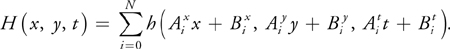
To reduce the number of texture fetches necessary for filtering, we build our texture in a special way, so that each texel contains all the data necessary for a single bilinear texture lookup. This is possible because our height maps are essentially one-component textures, and we can pack four height values into a single texel of a four-component texture:
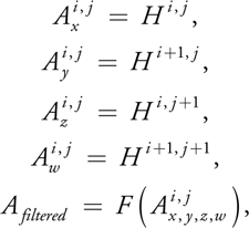
where i = 0..N - 1, j = 0..M - 1. H is our height map value, F is a filtering function, and A is the packed output texture.
Listing 18-2 implements bilinear texture lookup into vertex texture, packed as shown previously.
Example 18-2. Efficient Bilinear Texture Interpolation in Vertex Shaders
float tex2D_bilinear4x(uniform sampler2D tex, float4 t, float2 Scales)
{
  float size = Scales.x;
  float scale = Scales.y;
  float4 tAB0 = tex2Dbias(tex, t);
  float2 f = frac(t.xy * size);
  float2 tAB = lerp(tAB0.xz, tAB0.yw, f.x);
  return lerp(tAB.x, tAB.y, f.y);
}
We can extend this approach for trilinear filtering. Because trilinear filtering requires a fractional LOD value, we can use the distance from the camera as a good approximation of LOD. The code in Listing 18-3 implements trilinear texture lookup into the packed vertex texture.
Example 18-3. Extending the Bilinear Filtering Technique to Trilinear Filtering
float tex2D_trilinear(uniform sampler2D tex, float4 t, float2 Scales)
{
  float fr = frac(t.z);
  t.z -= fr;
  // floor(t.zw);
  float Res;
  if (fr < 0.30)
    Res = tex2D_bilinear4x(tex, t.xyzz, Scales);
  else if (fr > 0.70)
    Res = tex2D_bilinear4x(tex, t.xyzz + float4(0, 0, 1, 1),
                           Scales * float2(0.5, 2));
  else
  {
    Res = tex2D_bilinear4x(tex, t.xyzz, Scales);
    float Res1 = tex2D_bilinear4x(tex, t.xyzz + float4(0, 0, 1, 1),
                                  Scales * float2(0.5, 2));
    fr = saturate((fr - 0.30) * (1 / (0.70 - 0.30)));
    Res = Res1 * fr + Res * (1 - fr);
  }
  return Res;
}
Note that we've further optimized trilinear texture fetch by performing two texture lookups only in the region where the influence of both mip levels is significant. In other regions, we "snap" the LOD value to the closest mip level, thus saving on texture bandwidth.
Avoiding Unnecessary Work with Branching
Even with optimized texture filtering, the number of texture fetches during water rendering can still be high, which significantly affects performance. We could reduce the total number of rendered vertices, but that would lower overall visual detail and increase aliasing.
Because we render our water with large batches of geometry, some of the triangles end up being completely off-screen. Note that even for such triangles, the vertex program is still executed, wasting precious computational resources. We can save a significant amount of per-vertex work if we skip computation for triangles falling outside the camera frustum.
The vertex program operates at one vertex at a time and has no access to topological information, so we can make decisions only on the per-vertex level, but not on the per-triangle level. This can create artifacts if some of the vertices within a triangle skip vertex texturing and others don't. We have found that in practice our triangles and our vertex texture displacements are small enough for this artifact not to be detectable.
The following pseudocode illustrates this idea:
float4 ClipPos = mul(ModelViewProj, INP);
float3 b0 = abs(ClipPos.xyz) < (ClipPos.www * C0 + C1);
if (all(b0))
{
  // Vertex belongs to visible triangle,
  // Perform texture sampling and displace vertex accordingly
}
In the preceding code, we use the clip-space vertex position to determine if the current vertex lies within the frustum, and then we perform the expensive computations only when necessary.
The values C0 and C1 are special "fudge" constants that control how much triangles need to extend beyond the camera frustum to trigger clipping. That way, we avoid artifacts caused by skipping texturing for out-of-frustum vertices whose triangles are still visible. Effectively, we are making our "clipping" frustum slightly wider, allowing for a certain amount of "guard-band" space along screen edges. Because our water plane is tessellated finely enough and the vertex texture displacements are reasonable, this simple method works well in practice.
Using Render-to-Texture
We can also improve the speed of our approach by first combining our height map textures into a single floating-point texture in a separate pass. It then becomes unnecessary to perform multiple expensive filtering operations in the vertex shader. Additionally, we can now use a more compact texture format, 16-bit floating point, for storage of the original height maps. We could also store a sequence of animated height maps as slices of a 3D texture, which would make animation smoother.
With this optimization, our rendering loop becomes two passes:
- Combine the height maps using a special pixel shader by rendering a single quadrilateral into an fp32-texture. Texels in this texture map to the vertices of the radial mesh.
- Use the generated height map as a vertex texture to displace the radial mesh vertices, as described previously.
Back Sides of Waves
Because our lighting computations are performed in the pixel shader under the assumption that the water surface is flat, this approximation can cause visual artifacts in certain cases.
In the case depicted in Figure 18-4, we see the back side of the wave, even though it is directed outward from the viewer due to geometrical displacement and shouldn't be visible in reality. This results in disturbing bright areas at the tops of the waves.
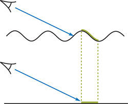
Figure 18-4 A Source of Rendering Artifacts
To minimize these artifacts, we adjust our normal vectors used for the lighting calculation by "tilting" them toward the viewer a bit, so that they correspond to the front faces of the wave more closely. You can find source code for this technique on the accompanying CD. Figure 18-5 shows a scene produced using the methods described in this chapter.
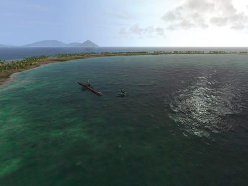
Figure 18-5 Extremely Realistic Water Rendered with Techniques Presented Here
18.2.5 Rendering Local Perturbations
Sometimes it is desirable to render local choppiness caused by buoyant objects or by objects falling into the water. This is especially important for games, where it is necessary to generate explosions, ship trails, or the like. Because it is hard to integrate physically correct methods in our height-map-based model of the water surface, we discuss simpler methods, based on heuristics.
Analytical Deformation Model
The simplest way to achieve local choppiness is to disturb displaced vertex positions analytically, by combining them with the computed vertex position in the vertex shader. For explosions, we can use the following formula:
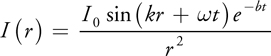
where r is the distance from the explosion center in the water plane and b is a decimation constant. The values of I 0,, and k are chosen according to a given explosion and its parameters.
For rendering, we can use the same radial grid as the one used for regular water rendering, but centered at the explosion location.
Dynamic Displacement Mapping
Another option is to render all of the locally generated displacements directly into the vertex texture, essentially implementing a general-purpose programming on the GPU (GPGPU) type of approach. That way, we generate a vertex texture in the first pass and then use it in a subsequent pass for the actual water rendering. As an additional benefit, we can offload some work from the vertex shaders by filtering the base height map and summing "octaves" in the pixel shader.
To calculate displacements, we can either employ the above-mentioned analytical model or try using a cellular-automata approach, by evolving local displacements from frame to frame. Wind effects can also be taken into account by blurring the texture along the appropriate direction.
However, to cover 1 km of water surface with 50 cm resolution, it would be necessary to use a texture about 2048x2048 in size, which would create additional pressure on texture memory and shader execution speed. Also, quick transitions of the viewpoint would be problematic.
Nevertheless, we encourage the reader to experiment with these approaches.
Foam Generation
When choppiness is strong enough, we can generate foam to further increase realism. The simplest way to do this is to blend in a precreated foam texture at vertices displaced above a certain height H 0. Transparency of the foam texture is calculated according to the following formula:
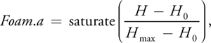
where H max is the height at which the foam is at maximum, H 0 is the base height, and H is the current height.
The foam texture can be animated to show the evolution of foam creation and dissipation. The animation sequence can be either created manually by artists or generated programmatically.
18.3 Conclusion
By combining the flexibility of vertex texture fetch and the performance-saving features of dynamic branching, we were able to develop a practical method for rendering realistic-looking water surfaces at interactive speeds. The approach described here was successfully applied in the title Pacific Fighters, and it allowed us to create a realistic water surface across a significant range of distances—from 10 cm up to 40 km. This is acceptable for modern flight simulators. We were able to eliminate tiling artifacts across the whole visible region of the water surface.
Future hardware is likely to enable even more robust implementations of the technique, in particular eliminating the need to manually perform filtering of the texture values, as well as providing even more vertex shader performance.
The quality of our approach can be increased even further by employing advanced shading techniques, such as parallax mapping, to provide fine-grained details and bumps on the water surface. See Chapter 8, "Per-Pixel Displacement Mapping with Distance Functions," for one approach like this.
Finally, lighting calculations could greatly benefit from high-dynamic-range techniques, because highly reflective water surfaces can exhibit huge brightness variations.
18.4 References
Fournier, Alain, and William T. Reeves. 1986. "A Simple Model of Ocean Waves." In Computer Graphics (Proceedings of SIGGRAPH 86), pp. 75-84.
Kryachko, Yuri. 2004. "Modelling Sea and River Water with Pixel Shader 2.0." Presentation. Available online at http://www.kriconf.ru/2004/rec/KRI-2004.Programming_20.ppt
Tessendorf, Jerry. 2001. "Simulating Ocean Water." In "Simulating Nature: Realistic and Interactive Techniques," SIGGRAPH 2001 course notes, course 47.
Copyright
Many of the designations used by manufacturers and sellers to distinguish their products are claimed as trademarks. Where those designations appear in this book, and Addison-Wesley was aware of a trademark claim, the designations have been printed with initial capital letters or in all capitals.
The authors and publisher have taken care in the preparation of this book, but make no expressed or implied warranty of any kind and assume no responsibility for errors or omissions. No liability is assumed for incidental or consequential damages in connection with or arising out of the use of the information or programs contained herein.
NVIDIA makes no warranty or representation that the techniques described herein are free from any Intellectual Property claims. The reader assumes all risk of any such claims based on his or her use of these techniques.
The publisher offers excellent discounts on this book when ordered in quantity for bulk purchases or special sales, which may include electronic versions and/or custom covers and content particular to your business, training goals, marketing focus, and branding interests. For more information, please contact:
U.S. Corporate and Government Sales
(800) 382-3419
corpsales@pearsontechgroup.com
For sales outside of the U.S., please contact:
International Sales
international@pearsoned.com
Visit Addison-Wesley on the Web: www.awprofessional.com
Library of Congress Cataloging-in-Publication Data
GPU gems 2 : programming techniques for high-performance graphics and general-purpose
computation / edited by Matt Pharr ; Randima Fernando, series editor.
p. cm.
Includes bibliographical references and index.
ISBN 0-321-33559-7 (hardcover : alk. paper)
1. Computer graphics. 2. Real-time programming. I. Pharr, Matt. II. Fernando, Randima.
T385.G688 2005
006.66—dc22
2004030181
GeForce™ and NVIDIA Quadro® are trademarks or registered trademarks of NVIDIA Corporation.
Nalu, Timbury, and Clear Sailing images © 2004 NVIDIA Corporation.
mental images and mental ray are trademarks or registered trademarks of mental images, GmbH.
Copyright © 2005 by NVIDIA Corporation.
All rights reserved. No part of this publication may be reproduced, stored in a retrieval system, or transmitted, in any form, or by any means, electronic, mechanical, photocopying, recording, or otherwise, without the prior consent of the publisher. Printed in the United States of America. Published simultaneously in Canada.
For information on obtaining permission for use of material from this work, please submit a written request to:
Pearson Education, Inc.
Rights and Contracts Department
One Lake Street
Upper Saddle River, NJ 07458
Text printed in the United States on recycled paper at Quebecor World Taunton in Taunton, Massachusetts.
Second printing, April 2005
Dedication
To everyone striving to make today's best computer graphics look primitive tomorrow
- Copyright
- Inside Back Cover
- Inside Front Cover
- Part I: Geometric Complexity
-
- Chapter 1. Toward Photorealism in Virtual Botany
- Chapter 2. Terrain Rendering Using GPU-Based Geometry Clipmaps
- Chapter 3. Inside Geometry Instancing
- Chapter 4. Segment Buffering
- Chapter 5. Optimizing Resource Management with Multistreaming
- Chapter 6. Hardware Occlusion Queries Made Useful
- Chapter 7. Adaptive Tessellation of Subdivision Surfaces with Displacement Mapping
- Chapter 8. Per-Pixel Displacement Mapping with Distance Functions
- Part II: Shading, Lighting, and Shadows
-
- Chapter 9. Deferred Shading in S.T.A.L.K.E.R.
- Chapter 10. Real-Time Computation of Dynamic Irradiance Environment Maps
- Chapter 11. Approximate Bidirectional Texture Functions
- Chapter 12. Tile-Based Texture Mapping
- Chapter 13. Implementing the mental images Phenomena Renderer on the GPU
- Chapter 14. Dynamic Ambient Occlusion and Indirect Lighting
- Chapter 15. Blueprint Rendering and "Sketchy Drawings"
- Chapter 16. Accurate Atmospheric Scattering
- Chapter 17. Efficient Soft-Edged Shadows Using Pixel Shader Branching
- Chapter 18. Using Vertex Texture Displacement for Realistic Water Rendering
- Chapter 19. Generic Refraction Simulation
- Part III: High-Quality Rendering
-
- Chapter 20. Fast Third-Order Texture Filtering
- Chapter 21. High-Quality Antialiased Rasterization
- Chapter 22. Fast Prefiltered Lines
- Chapter 23. Hair Animation and Rendering in the Nalu Demo
- Chapter 24. Using Lookup Tables to Accelerate Color Transformations
- Chapter 25. GPU Image Processing in Apple's Motion
- Chapter 26. Implementing Improved Perlin Noise
- Chapter 27. Advanced High-Quality Filtering
- Chapter 28. Mipmap-Level Measurement
- Part IV: General-Purpose Computation on GPUS: A Primer
-
- Chapter 29. Streaming Architectures and Technology Trends
- Chapter 30. The GeForce 6 Series GPU Architecture
- Chapter 31. Mapping Computational Concepts to GPUs
- Chapter 32. Taking the Plunge into GPU Computing
- Chapter 33. Implementing Efficient Parallel Data Structures on GPUs
- Chapter 34. GPU Flow-Control Idioms
- Chapter 35. GPU Program Optimization
- Chapter 36. Stream Reduction Operations for GPGPU Applications
- Part V: Image-Oriented Computing
-
- Chapter 37. Octree Textures on the GPU
- Chapter 38. High-Quality Global Illumination Rendering Using Rasterization
- Chapter 39. Global Illumination Using Progressive Refinement Radiosity
- Chapter 40. Computer Vision on the GPU
- Chapter 41. Deferred Filtering: Rendering from Difficult Data Formats
- Chapter 42. Conservative Rasterization
- Part VI: Simulation and Numerical Algorithms
-
- Chapter 43. GPU Computing for Protein Structure Prediction
- Chapter 44. A GPU Framework for Solving Systems of Linear Equations
- Chapter 45. Options Pricing on the GPU
- Chapter 46. Improved GPU Sorting
- Chapter 47. Flow Simulation with Complex Boundaries
- Chapter 48. Medical Image Reconstruction with the FFT