
GPU Gems 2
GPU Gems 2 is now available, right here, online. You can purchase a beautifully printed version of this book, and others in the series, at a 30% discount courtesy of InformIT and Addison-Wesley.
The CD content, including demos and content, is available on the web and for download.
Chapter 13. Implementing the mental images Phenomena Renderer on the GPU
Martin-Karl Lefrançois
mental images
13.1 Introduction
mental images' rendering software mental ray is the rendering component of many leading 3D content-creation tools, including industrial CAD, product design, and architectural design software packages. mental ray is widely used for the creation of visual effects and feature animation films, as well as for high-quality visualization and lighting simulation in industrial and architectural design. Now that modern GPUs can execute complex programs to compute the color of each shaded pixel, there is an opportunity to apply this power to rendering complex scenes that previously could be handled only by a CPU-based renderer. Given the substantial floating-point computational power available on GPUs, doing these computations on the GPU can be much faster than on the CPU. This chapter describes some of the work that mental images has done to add support for GPU-based rendering to mental ray.
Because the per-fragment mathematical computation done by a GPU can now be identical to the computation done by a software renderer, it is possible to use the GPU to accelerate rendering of the final image. Although some techniques, such as software ray tracing, cannot yet be replaced with an efficient GPU-based solution due to the limitations of current hardware, there are many scenes that do not require these techniques. Such scenes can be entirely rendered by the GPU. In some cases, we still have to combine software and hardware rendering to achieve the final image, but hardware technology evolves so fast that we will see more and more of the work shifting to the GPU.
One of the main difficulties with rendering high-quality imagery on the GPU is making it possible to use the same shaders on the GPU as on the CPU. Production companies use a carefully developed set of shaders that they combine to create the final effect they want. With most GPU programming languages, it is difficult to efficiently combine shaders, because the languages are designed for monolithic programs that implement a complete effect. However, the release of Cg 1.2 was a breakthrough for the creation of complex shaders on the GPU: with the addition of shader interfaces and unsized arrays to the language, it became possible to combine shaders at runtime to generate GPU programs that render the desired final effect.
In this chapter, we briefly review mental ray's 3.3/3.4 shading architecture and describe how we convert combinations of mental ray shaders to GPU programs. The techniques we use provide a powerful and flexible means of creating complex visual effects. We are now able to accelerate rendering of final images with the GPU without sacrificing quality or visual richness.
13.2 Shaders and Phenomena
For high-quality offline rendering, the concept of a "shader" is a slightly different one than for interactive rendering on GPUs. On the GPU, vertex shaders and fragment shaders operate on the input geometry to compute the color of each pixel. In mental ray, shaders are plug-in modules that are used in materials, light sources, cameras, and other elements to control a wide range of effects, from surface material, volume, and camera lens properties to compositing. High-end visual effects and feature animation production companies keep separate effect components in separate shaders that are combined automatically at runtime; it often makes more sense to divide particular visual effects into smaller elements that separately represent the environment and what interacts with it. As an example, objects carry surface shaders that define the response of the surface to incident light (that is, the BRDF). Lights are separate scene elements that carry light shaders that define the light emission characteristics. Both need to be combined at runtime to perform shading. Additionally, there are volume shaders; lens shaders attached to cameras; texture, environment, and other shaders that all contribute to shading and must be collected to create the fragment program.
When a software renderer renders a scene, different shaders are called in different stages of the pipeline. In the following example, the first shader to be called is the material shader, which defines the color of the illuminated surface. Then the light shaders of all of the lights illuminating this surface will be called in order to determine how much illumination they shine on the surface. Light shaders behave differently depending on whether they are point, spot, or area lights. If the surface is reflective, the environment shader may be called to add its contribution to the surface. If ray tracing is enabled, a ray might hit another object, whose material shader will then be called. If the object is transparent, the material and light shaders will be called again until full opacity is achieved. In addition to all those shaders, volume shaders, such as fog, can affect the final image. The volume shader, if attached to the camera, will be called for every sample. Figure 13-1 illustrates these basic concepts.
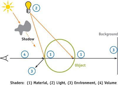
Figure 13-1 Shaders in a Scene
The mental ray renderer further extends this idea to include Phenomenon components (Driemeyer 2005). These look like shaders when they are applied to the scene, but their functionality is implemented in a different way. Whereas shaders usually function as standalone components, Phenomena encapsulate sets of subshader nodes connected to form graphs, as well as associated rendering options, geometry, material, volumes, and other elements that are automatically integrated at appropriate points in the scene. (Phenomena are a superset of Maya's Hypershade graphs, for example.) Both shaders and Phenomena have interface parameters that feed data into them and result parameters that return the result of their evaluation. In the case of Phenomena, the result parameters of the Phenomenon are taken from a specific shader that is called the main root shader of the Phenomenon.
Once defined, the shader can be used to control the surface properties of a material. Shaders and Phenomena can be connected to form shader graphs. In mental ray, users can assign the result parameter of another shader to an interface parameter.
Figure 13-2 shows an example of a Phenomenon. It uses three input parameter values to compute the result. These parameter values in turn may be computed by other shaders, may be constants set by the user, may be the results of texture lookups, and so on. Note that in this case, the final result value is computed by another "sub" Phenomenon in the blue box. This ability to "wire up" Phenomenon graphs in many different ways, using modular pieces, makes them a powerful paradigm for artists and designers.
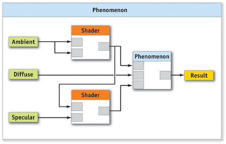
Figure 13-2 An Example of a Phenomenon
In the schematic diagrams in this chapter, boxes represent shaders or Phenomena; their interface parameters (such as "ambient," "diffuse," or "specular") are on the left side and the result parameters are on the right side. Phenomenon instances are useful as prepackaged effects: a wood Phenomenon, for example, may have parameters that define colors and wood grain turbulence, and different predefined instances of it can supply parameter values to make it look like oak, redwood, birch, or other variations.
When using shaders or Phenomena in a scene, you need to know three properties:
- The name of the shader or Phenomenon
- Its interface parameters
- Its result parameter
The shader name is identical to the name of the Cg structure type that implements it. The interface parameters are a set of named values passed to the shader or Phenomenon when it runs. For example, a shader implementing Phong shading could have three interface parameters of type color named ambient, diffuse, and specular and one of type scalar named exponent. Finally, the result parameters of a shader represent the values returned by the shaders. Most of the time, this is a single value of type color, but other types and structures of multiple values are also possible.
13.3 Implementing Phenomena Using Cg
Because GPUs do not support loading multiple shaders and then having one shader call another shader at runtime, mental ray must collect the Phenomenon—including all subshaders that feed its input parameters, root shaders, and assigned shaders (such as light shaders that illuminate the surface)—into a single fragment program that can be downloaded to the GPU. The shader interfaces feature introduced in Cg 1.2 (Pharr 2004) facilitates this process.
In our system, we have predefined an abstract Cg interface type for each of the parameter types that may be passed as input, or computed as output, by a shader component. Shaders and Phenomena are written to use these abstract interface types when declaring input and output parameters. At runtime, concrete instances of each subshader are created using the Cg runtime library, and the outputs of each internal subshader are connected to the proper inputs, as shown in Figure 13-3.
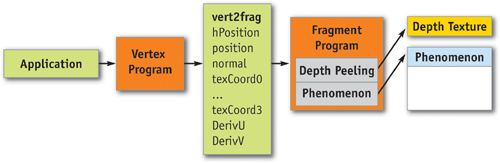
Figure 13-3 How a Phenomenon Fits into the Graphics Pipeline
The rest of this section provides details on the GPU programs we use, the interface types we define, and how output parameters are connected to the inputs of other shaders to form graphs.
13.3.1 The Cg Vertex Program and the Varying Parameters
We have found that for the majority of effects we want to achieve, we can use the same vertex program. This vertex program primarily serves as a simple pass-through for the data coming from the application. The most common varying parameters are transformed in the vertex shader and passed to the fragment shader.
In addition to the homogeneous position, the following varying parameters are sent to the fragment programs: the position, the normal, four texture coordinates, and the surface's parametric derivatives in U and V for bump mapping. All data, except texture coordinates, are transformed to camera space for simplicity. For example, the position in the fragment corresponds to the vector from the camera to the rendered pixel in eye space, and the length of the vector corresponds to the distance from the camera. In the fragment program, transformation matrices are available to convert from one space to another if needed. The varying parameters from the vertex program to the fragment program are stored in a structure called vert2frag, shown in Listing 13-1.
Example 13-1. The Varying Parameters Sent to the Fragment Program
struct vert2frag
{
  float4 hPosition : POSITION;
  // Homogeneous position
  float2 texCoord0 : TEXCOORD0; // Texture coordinates
  float2 texCoord1 : TEXCOORD1; // Texture coordinates
  float2 texCoord2 : TEXCOORD2; // Texture coordinates
  float2 texCoord3 : TEXCOORD3; // Texture coordinates
  float3 position : TEXCOORD4;
  // Eye-space position
  float3 normal : TEXCOORD5;
  // Eye-space normal
  float3 derivU : TEXCOORD6;
  // Derivative U
  float3 derivV : TEXCOORD7;
  // Derivative V
  float2 screen : WPOS;
  // Screen space
  float4 face : COLOR0;
  // 1 front, -1 back
};
13.3.2 The main() Entry Point for Fragment Shaders
All fragment programs composed from component shaders by mental ray must start with an entry function. To be able to translate Phenomena to the GPU, we had to come up with a common main entry point. For all shader graphs, we create a main() function that calls the appropriate Phenomenon root shader, which triggers the evaluation of the entire graph of shaders.
This main entry point also handles some general operations required in all shaders. For example, it includes a test for discarding pixels nearer than the z-depth texture, which is used for order-independent transparency.
13.3.3 The General Shader Interfaces
Support for interfaces was introduced in Cg 1.2. These interfaces provide a way to abstract how member functions in structures are implemented. We use them heavily to implement the value returned to a parameter of a shader. To be able to connect the output of one shader with the input parameters of other shaders, we have to define general Cg interface types that are used by all shaders. These default Cg interface types and their implementation are automatically inserted in each program. For each parameter type found in the description of the shader, an equivalent interface exists. As an example, if an input parameter is of type scalar in the declaration of the shader, it needs to be declared miiScalar in the Cg implementation of the shader.
Table 13-1 shows the corresponding parameter and interface types.
Table 13-1. mental ray Basic Type and Corresponding Cg Interfaces
|
mental ray Type |
Cg Interface Type |
Return Value |
|
light |
miiLight |
misLightOut |
|
boolean |
miiBoolean |
bool |
|
integer |
miiInteger |
int |
|
scalar |
miiScalar |
float |
|
vector |
miiVector |
float3 |
|
color |
miiColor |
float4 |
|
color texture |
miiColorTexture |
float4 |
|
matrix |
miiMatrix |
float4x4 |
Each Cg interface type defines a single evaluation method, named eval(), that returns a value of the corresponding concrete type. For example:
// integer
interface miiInteger(int eval(vert2frag params););
// vector
interface miiVector(float3 eval(vert2frag params););
To write a shader that serves as a concrete implementation of an interface type, we simply define a struct that implements the appropriate eval() method. This allows us to "plug in" the struct wherever the corresponding interface type is called for.
As an example, the following case shows the implementation of miiScalar, in which we want a simple constant value to be assigned to an interface parameter. We create and connect a simple implementation of the interface, which causes a constant value to be returned by the eval() method:
// base scalar implementation
struct miScalar : miiScalar
{
  float s;
  float eval(vert2frag params) { return s; }
};
13.3.4 Example of a Simple Shader
mental ray needs to know how shaders are defined to properly call them and assign values to the shader's parameter. Here is an example of a shader declaration as it can be found when parsing a mental ray scene:
declare shader color
    "mib_illum_phong"(color "ambience", color "ambient", color "diffuse",
                      color "specular", scalar "exponent",
#phong exponent
                      integer "mode",
#light selection mode 0..2
                      array light "lights")end declare
When writing fragment shaders, we follow a simple rule: in the Cg file implementing the shader, we define a structure that implements the interface corresponding to the return value of the shader as required by the declaration of the shader. The structure should also have the input parameters of the shader and an eval() method for the return interface.
The name of the structure is the same name found in the declaration of the shader. It must implement the return type interface also found in the shader declaration. All of the shader's required input parameters must be defined using their equivalent type interfaces. They also must have the same name as found in the shader declaration.
For a single shader, an instance of the shader will be created and connected to the main root of the Phenomenon. And when no shaders are attached to the input parameters, a simple interface that evaluates to a constant is connected, the variability of which is set to CG_LITERAL using the Cg runtime. Setting the variability to CG_LITERAL allows the Cg compiler to optimize the resulting fragment shader (by using constant folding) to a greater degree than if a uniform value were used.
As shown in Listing 13-2, the name of the structure is the same as the shader declaration. The structure implements the interface miiColor, which corresponds to the output parameter. Not all input parameters are needed; for example, the parameter mode is ignored in the Cg shader.
The graph in Figure 13-4 shows an example of the connection of values in the shader. Some parameters are omitted for clarity.
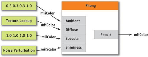
Figure 13-4 An Example of a Simple Shader
Example 13-2. Cg Implementation of the Phong Illumination Model
struct mib_illum_phong : miiColor
{
  miiColor ambience, ambient, diffuse, specular;
  miiScalar exponent;
  miiLight lights[];
  // Implementation of miiColor
  float4 eval(vert2frag p)
  {
    float4 result;
    float4 ldiffuse = diffuse.eval(p);
    float4 lspecular = specular.eval(p);
    float lexponent = exponent.eval(p) result =
        ambience.eval(p) * ambient.eval(p);
    // Material calculation for each light
    for (int i = 0; i < lights.length; i++)
    {
      // Light shader evaluation
      misLightOut light = lights[i].eval(p);
      // Lambert's cosine law
      float d = max(0, light.dot_nl);
      result += d * ldiffuse * light.color;
      // Phong's cosine power
      if (d > 0)
      {
        float s = mi_phong_specular(lexponent, light.dir, vdir, p.normal);
        result += s * lspecular * light.color;
      }
    }
    return result;
  }
};
13.3.5 Global State Variables
Shaders may need additional information that is not passed to them via interface parameters. For example, it might be important to know the current object being rendered or the resolution of the final image. Also, many shaders need to convert from one coordinate space to another, which requires access to various transformation matrices. Our system uses specific global state variables to provide these values. For example, when creating a program, our system iterates through its global parameters looking for any named "miToWorld". If the program contains this parameter name and if the type corresponds to float4x4, it is initialized with the appropriate transformation matrix. Table 13-2 shows the variables that can be used.
Table 13-2. mental ray Global State Variables
|
Usage |
State Variable Name |
Cg Type |
Description |
|
Material |
miToWorld |
float4x4 |
Matrix for transforming camera-space coordinates found in vert2frag.position to world space. |
|
miFromWorld |
float4x4 |
Matrix for transforming world-space coordinates to camera space. |
|
|
miToObject |
float4x4 |
Matrix for transforming camera-space coordinates to object space. |
|
|
miFromObject |
float4x4 |
Matrix for transforming object-space coordinates to camera space. |
|
|
Light Shaders Only |
miLightOrigin |
float3 |
Position of the light in camera space. |
|
miLightDir |
float3 |
Direction of the light in camera space. |
|
|
miLightSpread |
float |
Spread angle for spotlights. |
|
|
miLightType |
int |
Type of the light: 0 = point, 1 = spot, 2 = directional |
|
|
miLightFace |
int |
Lighting face: 1 = front, 2 = back, 0 = both |
|
|
miToLight |
float4x4 |
Matrix for transforming camera-space coordinates to light space. |
|
|
miFromLight |
float4x4 |
Matrix for transforming light-space coordinates to camera space. |
|
|
Camera |
miCameraAspect |
float |
Aspect ratio: height x aspect = width |
|
miCameraAperture |
float |
Aperture size: atan(focal/aperture) = field of view |
|
|
miCameraFocal |
float |
Focal length: atan(focal/aperture) = field of view |
|
|
miCameraClip |
float2 |
Clip plane: x = near, y = far |
|
|
miCameraRes |
float2 |
Resolution of the window. |
|
|
miCameraOrtho |
bool |
Is the camera orthographic? |
|
|
Shadow Map (Light Shaders Only) |
miShadowMap |
bool |
If true, the global shadow map option is on. |
|
miShadowMapTex |
samplerRECT[1|6] |
Shadow map textures. 1 for spot and directional lights, 6 for point lights. |
|
|
miShadowMapTransform |
float4x4 |
Matrix for transforming vert2frag.position to light space. |
|
|
miShadowMapWindow |
float2 |
The transformation to apply to UV coordinates. |
|
|
miShadowMapSize |
float2 |
The resolution of the shadow map. |
|
|
miShadowMapBias |
float |
The bias applied to the shadow map. |
|
|
Shader |
miRayEnvironment |
miiColor |
Connection to the environment shader. |
These state variables are created as shared parameters using the Cg runtime. When we find a known state parameter as a program's global parameter, we just connect it to the corresponding global uniform parameter. When the value changes during a frame, we only have to update the value of the shared parameter to have the value updated in each shader that has a parameter bound to it. This use of uniform values is illustrated in Figure 13-5.
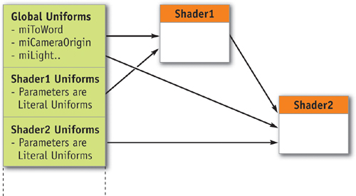
Figure 13-5 How Global Uniforms Are Shared
13.3.6 Light Shaders
Light shaders implement the characteristics of a light source. For example, a spotlight shader would use the illumination direction to attenuate the amount of light emitted within a cone. A light shader is called whenever a material shader uses the light interface to evaluate a light. In production scenes, we often find a lot of different lights illuminating a model. In our implementation, all light shaders must return a structure containing the amount of contributed color from the light, the direction to the light, and the dot product of the light direction and the normal. Because surface shaders are written to call out to the abstract light interface to get these values back, it is easy to use any type of light that implements this interface with any type of surface shader.
Light shaders are also responsible for shadow casting, as illustrated in Figure 13-6. In the light shader, we can compute whether or not the fragment is currently visible to the light source, using a shadow map rendered in a previous pass or a software-generated one. If the fragment is not visible, the light will typically return a black color, meaning there will be no light contribution to the illumination of the material.
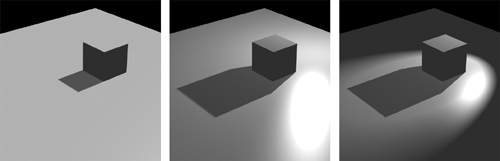
Figure 13-6 Directional, Point, and Spotlight Illumination and Shadow Map
Listing 13-3 is a sample implementation of a spotlight.
Example 13-3. Partial Cg Implementation of the mental ray Base Spotlight
struct mib_light_spot : miiLight
{
  // parameters of the shader
  miiColor color;
  miiBoolean shadow;
  miiScalar factor;
  miiBoolean atten;
  miiScalar start;
  miiScalar stop;
  miiScalar cone;
  // Information from the light instance
  // position of the light
  float3 miLightOrigin;
  // direction of the light
  float3 miLightDir;
  // cos angle of the spread
  float miLightSpread;
  bool miShadowMap;
  // Shadow active or not?
  samplerRECT miShadowMapTex[1]; // light shadow map
  float4x4 miShadowMapTransfo;
  // From camera to light space
  float2 miShadowMapWindow;
  // size of the window
  float2 miShadowMapSize;
  // size of the shadow map
  float miShadowMapBias;
  // Evaluation of the light
  misLightOut eval(vert2frag p)
  {
    misLightOut ret_val;
    float4 lcolor = color.eval(p);
    // vector to light
    ret_val.dir = normalize(miLightOrigin - p.position);
    ret_val.dot_nl = dot(p.normal, ret_val.dir);
    // shadow
    if (shadow.eval(p) && miShadowMap)
    {
      float lfactor = factor.eval(p);
      ... lcolor.rgb *= lerp(lfactor, 1, map_z / 4);
    }
    // cone
    ...
        // dist attenuation
        ... ret_val.color = lcolor;
    return ret_val;
  }
};
13.3.7 Texture Shaders
Texture shaders typically return a color from a texture image. They can also be procedural, like the classic marble or wood shaders. When a shader input parameter is attached to a texture image, an explicit miColorTexture parameter is created and its texture ID is mapped to the sampler2D parameter. By enabling automatic Cg runtime texture parameter management with a call to cgGLSetManageTextureParameters(), we do not have to handle the activation of the texture when the program is bound. This way we can load all textures and simply use cgSetTextureParameter() to access the image in the shader.
All evaluation methods of the basic interface need only one parameter, the vert2frag structure, except for the miiColorTexture interface. In addition to the usual varying parameters, we also add a float2 parameter to pass the UV coordinates.
One nice thing about texture shaders is the ability to generate procedural texture coordinates. Usually UVs are attached to each vertex and are often generated from texture projections. These projections can be created in fragment programs, which can resolve all the artifacts that often arise when applying spherical mappings or other parametric projections at the vertex level.
Figure 13-7 (on the next page) shows a texture shader output, connected to the diffuse parameter of the Phong shader. The texture coordinates are calculated per fragment with a spherical projection.
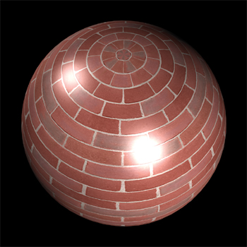
Figure 13-7 A Texture Shader Connected to the Diffuse Parameter of
Listing 13-4 is an example of a simple texture-lookup shader that returns a color.
Example 13-4. Cg Implementation of the mental ray Texture Lookup Shader
struct mib_texture_lookup : miiColor
{
  miiColorTexture tex;
  miiVector coord;
  float4 eval(vert2frag p)
  {
    // Evaluation of the spherical projection shader
    float3 lcoord = coord.eval(p);
    // Evaluate to a simple tex2D call
    float4 ret_val = tex.eval(p, lcoord.xy);
    return ret_val;
  }
};
13.3.8 Bump Mapping
In Figure 13-8, the normal vector used for the illumination of a material is perturbed by the bump-map shader. To apply bump mapping to a material shader, we have to modify the varying state normal before the evaluation of the material shader. We do this by adding an extra shader node to our graph, as illustrated in Figure 13-9. The interface of this node takes two parameters: the first one calls the normal modifier and returns the value to the varying state normal; the second parameter calls the material shader. Because the normal used by the material shader has been modified before its evaluation, the lighting is appropriately affected by the bump.
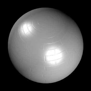
Figure 13-8 with the Normal Modified Using a Bump-Map Shader
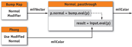
Figure 13-9 The Structure of a Bump Map Shader
Because this is a shader returning a vector, the shader implementing the normal modifier can be of any type. It can be a normal texture lookup, it can modify the normal based on multiple texture lookups, or it can be procedural. The derivatives sent through the varying parameter ensure that you always sample in the same direction and that the bumps rotate appropriately with the object.
13.3.9 Environment and Volume Shaders
The environment shader is an optional extra root of Phenomena that is evaluated if a ray goes to infinity. It can be called for reflective or transparent surfaces, or simply when there are no objects visible in a particular pixel. To make sure we are calling the environment shader for all such pixels of the rendered image, we draw a plane at epsilon in front of the camera's far clip plane.
Because fully general ray tracing is not yet supported on the GPU, reflective or refractive materials do not have the option of sending rays and hitting other objects or themselves. Therefore, they can only reflect their environment. To call the global environment shader graph from another shader, we must define a global state variable. In Figure 13-10, we show the connection between the graph and the global state variable miRayEnvironment of type miiColor.
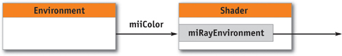
Figure 13-10 The Structure of an Environment Shader
Volume shaders are another Phenomenon root. These shaders need to be called for every rendered fragment. The volume shader attached to the camera affects the rendered color depending on different factors. One simple volume model is fog, which attenuates the color based on the distance to the camera. Because volume shaders need to be called for every fragment, the shader node is placed automatically on top of the main Phenomenon root, as illustrated in Figure 13-11.
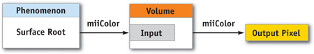
Figure 13-11 The Structure of a Volume Shader
In Figure 13-12, the blue shader for the spikes does not need to be modified due to the fog effect applied in this scene. The layer fog shader attached to the camera modifies the output of each of the scene's shaders, giving an atmospheric effect to the scene.
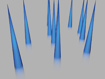
Figure 13-12 Image Rendered Using a Volume Shader
13.3.10 Shaders Returning Structures
Shaders are not limited to returning a single value; they can have multiple results. The values computed in such shaders are returned as a structure. A shader input parameter might connect to one of the members of the structure. Because Cg cannot connect interfaces of different types, we must implement converters.
First, the shader that returns the structure must implement the interface of this structure. This interface is needed to connect to a converter. All members of the structure must have a converter node in order to be connected to a shader parameter. A shader returning a color and a vector will have to implement two converters: a structure mystruct_outColor implementing miiColor and a structure mystruct_outVector implementing miiVector. The converter has its input parameter connected to the output of the shader and returns a member of that structure. The resulting structure member can now be connected to the destination shader parameter.
Converters can be used by many shaders. To avoid duplicating them, we simply include the converter code using an #include statement. Figure 13-13 shows the conversion from an output structure containing a vector to an miiVector.
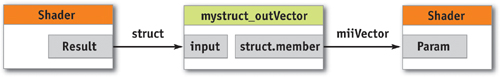
Figure 13-13 A Shader that Returns a Structure
13.3.11 Rendering Hair
In mental ray, hairs are rendered as Bezier curves. Hair width can be specified using a global radius, a per-hair radius, or a per-vertex radius. The approximation of the curves can generate millions of triangles when rendered with the GPU, each often smaller than a fragment. Because hairs are converted to triangles, they can be treated like any other geometry. We can attach a Phenomenon and use the varying parameter to follow the tangent of the hair, the distance from the root relative to the tip, and so on. This information is sufficient to implement any lighting model, because there is no fundamental difference between a hair Phenomenon and any other material Phenomenon. Figure 13-14 shows an example.
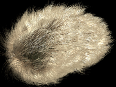
Figure 13-14 A Rendered Hairy Bean
13.3.12 Putting It All Together
When rendering a scene, we start collecting all the lights that need to cast shadow maps. mental ray also uses a Cg shader for evaluating the distance to the light, and the result is stored in a floating-point pbuffer.
We then convert all Phenomena to Cg and construct a unique tree from the different roots. If the resulting shader tree compiles successfully for the profile of the graphics card, the object is drawn by the GPU; otherwise, software renders it.
Because some materials are transparent, we draw the entire scene using an order-independent-transparency technique, also known as depth peeling (Everitt 2001). The shaders know the distance between each level and adjust the color contribution to the frame buffer. This is, for example, how we render hair primitives.
When all render passes are completed in hardware, the frame buffer is merged using the z-depth value and alpha to blend with the software pass.
During this process, a number of things can go wrong. For example, there might not be enough video or texture memory, or the Cg shader may not compile because of hardware limitations. In any of these cases, the objects in which errors occurred are rendered with software.
13.4 Conclusion
Phenomena converted to Cg and Phenomena evaluated by software produce the same result, and in the end, the hardware-rendered image is not noticeably different from the software-rendered version, which was our original goal. With hardware multisampling and supersampling, we can achieve comparable image quality as with software, and rendering on the GPU takes just a small fraction of the time needed for software to render a frame.
In complex production scenes, compiling the numerous shaders takes some time during preprocessing of the scene. Sometimes the Cg compiler overhead can reduce the overall gain from high-speed hardware rendering. But when shaders are compiled and all textures reside in video memory, there is no doubt that using the GPU to render the scene is far faster than using the CPU. With numerous test scenes, we have found that GPUs consistently render an order of magnitude or more faster than CPUs.
GPUs are now so fast that we can push the limit on the numbers of triangles in a scene. Because all triangles do not need to be resident in memory, we can render scenes that are very expensive to render in software. On the other hand, mental ray's software renderer provides functionality that cannot yet be achieved by hardware. Knowing the limitations of the hardware, we can create scenes to exploit its strengths and reduce rendering time by one or two orders of magnitude.
At the time this chapter was written, we noticed that the time to render a frame was being cut by more than a factor of two per year. Each new generation of GPUs provides more power and more memory, and overcomes more limitations. In the near future, current hardware limitations will disappear and will make the usage of GPUs even more common. We think that by 2010, almost all rendering will be GPU based.
13.5 References
Driemeyer, Thomas, ed. 2005. Rendering with Mental Ray, 3rd ed. Springer.
Everitt, Cass. 2001. "Order-Independent Transparency." Technical report. NVIDIA Corporation. Available online at http://developer.nvidia.com/view.asp?IO=order_independent_transparency
Pharr, Matt. 2004. "An Introduction to Shader Interfaces." In GPU Gems, edited by Randima Fernando, pp. 537–550. Addison-Wesley.
Copyright
Many of the designations used by manufacturers and sellers to distinguish their products are claimed as trademarks. Where those designations appear in this book, and Addison-Wesley was aware of a trademark claim, the designations have been printed with initial capital letters or in all capitals.
The authors and publisher have taken care in the preparation of this book, but make no expressed or implied warranty of any kind and assume no responsibility for errors or omissions. No liability is assumed for incidental or consequential damages in connection with or arising out of the use of the information or programs contained herein.
NVIDIA makes no warranty or representation that the techniques described herein are free from any Intellectual Property claims. The reader assumes all risk of any such claims based on his or her use of these techniques.
The publisher offers excellent discounts on this book when ordered in quantity for bulk purchases or special sales, which may include electronic versions and/or custom covers and content particular to your business, training goals, marketing focus, and branding interests. For more information, please contact:
U.S. Corporate and Government Sales
(800) 382-3419
corpsales@pearsontechgroup.com
For sales outside of the U.S., please contact:
International Sales
international@pearsoned.com
Visit Addison-Wesley on the Web: www.awprofessional.com
Library of Congress Cataloging-in-Publication Data
GPU gems 2 : programming techniques for high-performance graphics and general-purpose
computation / edited by Matt Pharr ; Randima Fernando, series editor.
p. cm.
Includes bibliographical references and index.
ISBN 0-321-33559-7 (hardcover : alk. paper)
1. Computer graphics. 2. Real-time programming. I. Pharr, Matt. II. Fernando, Randima.
T385.G688 2005
006.66—dc22
2004030181
GeForce™ and NVIDIA Quadro® are trademarks or registered trademarks of NVIDIA Corporation.
Nalu, Timbury, and Clear Sailing images © 2004 NVIDIA Corporation.
mental images and mental ray are trademarks or registered trademarks of mental images, GmbH.
Copyright © 2005 by NVIDIA Corporation.
All rights reserved. No part of this publication may be reproduced, stored in a retrieval system, or transmitted, in any form, or by any means, electronic, mechanical, photocopying, recording, or otherwise, without the prior consent of the publisher. Printed in the United States of America. Published simultaneously in Canada.
For information on obtaining permission for use of material from this work, please submit a written request to:
Pearson Education, Inc.
Rights and Contracts Department
One Lake Street
Upper Saddle River, NJ 07458
Text printed in the United States on recycled paper at Quebecor World Taunton in Taunton, Massachusetts.
Second printing, April 2005
Dedication
To everyone striving to make today's best computer graphics look primitive tomorrow
- Copyright
- Inside Back Cover
- Inside Front Cover
- Part I: Geometric Complexity
-
- Chapter 1. Toward Photorealism in Virtual Botany
- Chapter 2. Terrain Rendering Using GPU-Based Geometry Clipmaps
- Chapter 3. Inside Geometry Instancing
- Chapter 4. Segment Buffering
- Chapter 5. Optimizing Resource Management with Multistreaming
- Chapter 6. Hardware Occlusion Queries Made Useful
- Chapter 7. Adaptive Tessellation of Subdivision Surfaces with Displacement Mapping
- Chapter 8. Per-Pixel Displacement Mapping with Distance Functions
- Part II: Shading, Lighting, and Shadows
-
- Chapter 9. Deferred Shading in S.T.A.L.K.E.R.
- Chapter 10. Real-Time Computation of Dynamic Irradiance Environment Maps
- Chapter 11. Approximate Bidirectional Texture Functions
- Chapter 12. Tile-Based Texture Mapping
- Chapter 13. Implementing the mental images Phenomena Renderer on the GPU
- Chapter 14. Dynamic Ambient Occlusion and Indirect Lighting
- Chapter 15. Blueprint Rendering and "Sketchy Drawings"
- Chapter 16. Accurate Atmospheric Scattering
- Chapter 17. Efficient Soft-Edged Shadows Using Pixel Shader Branching
- Chapter 18. Using Vertex Texture Displacement for Realistic Water Rendering
- Chapter 19. Generic Refraction Simulation
- Part III: High-Quality Rendering
-
- Chapter 20. Fast Third-Order Texture Filtering
- Chapter 21. High-Quality Antialiased Rasterization
- Chapter 22. Fast Prefiltered Lines
- Chapter 23. Hair Animation and Rendering in the Nalu Demo
- Chapter 24. Using Lookup Tables to Accelerate Color Transformations
- Chapter 25. GPU Image Processing in Apple's Motion
- Chapter 26. Implementing Improved Perlin Noise
- Chapter 27. Advanced High-Quality Filtering
- Chapter 28. Mipmap-Level Measurement
- Part IV: General-Purpose Computation on GPUS: A Primer
-
- Chapter 29. Streaming Architectures and Technology Trends
- Chapter 30. The GeForce 6 Series GPU Architecture
- Chapter 31. Mapping Computational Concepts to GPUs
- Chapter 32. Taking the Plunge into GPU Computing
- Chapter 33. Implementing Efficient Parallel Data Structures on GPUs
- Chapter 34. GPU Flow-Control Idioms
- Chapter 35. GPU Program Optimization
- Chapter 36. Stream Reduction Operations for GPGPU Applications
- Part V: Image-Oriented Computing
-
- Chapter 37. Octree Textures on the GPU
- Chapter 38. High-Quality Global Illumination Rendering Using Rasterization
- Chapter 39. Global Illumination Using Progressive Refinement Radiosity
- Chapter 40. Computer Vision on the GPU
- Chapter 41. Deferred Filtering: Rendering from Difficult Data Formats
- Chapter 42. Conservative Rasterization
- Part VI: Simulation and Numerical Algorithms
-
- Chapter 43. GPU Computing for Protein Structure Prediction
- Chapter 44. A GPU Framework for Solving Systems of Linear Equations
- Chapter 45. Options Pricing on the GPU
- Chapter 46. Improved GPU Sorting
- Chapter 47. Flow Simulation with Complex Boundaries
- Chapter 48. Medical Image Reconstruction with the FFT