
GPU Gems 2
GPU Gems 2 is now available, right here, online. You can purchase a beautifully printed version of this book, and others in the series, at a 30% discount courtesy of InformIT and Addison-Wesley.
The CD content, including demos and content, is available on the web and for download.
Chapter 5. Optimizing Resource Management with Multistreaming
Oliver Hoeller
Piranha Bytes
Kurt Pelzer
Piranha Bytes
One of the most difficult problems in modern real-time graphics applications is the massive amount of data that must be managed. Complex scenes with complex meshes combined with multiple render passes—as are needed for high-quality shadows and additional reflection and refraction effects, for example—are expensive to render. Finding ways to feed the GPU with optimally formatted data is crucial for successfully rendering complex scenes.
This chapter addresses this issue and focuses on a flexible model to resolve the problem of handling the gamut of graphics hardware found in current PCs. A PC game must be able to run and run well on the latest high-end GPU all the way down to last year's "value" GPU—and on everything in between. We introduce a solution that handles the massive amount of data and is careful to transmit only the currently needed vertex components for each pass. This system, which has been implemented in the Gothic III engine, combines two powerful techniques: several vertex buffers are combined via multistreaming (a feature introduced with Microsoft DirectX 8.0), and each vertex buffer is controlled by an optimized resource manager. We present both the abstract concept as well as its implementation based on DirectX 9.0c.
5.1 Overview
Each vertex in a mesh has multiple components associated with it (position, normal, tangent, texture coordinates, and so on), but all of these entities aren't always necessary when rendering the object. We want an automated system that uses only the currently needed vertex components. To handle the task, we use vertex buffer streams specialized for certain subtasks. Depending on the current rendering pass, subsets of these streams are combined to assemble the vertices.
We need four basic types of streams, as shown in Figure 5-1. Here are the streams and their subtasks:
- G—Vertex stream for geometry data. Contains vertex position, normal, and vertex color(s).
- T—Vertex stream for texture-mapping data. Holds texture coordinate sets and additional information such as tangent vectors for tangent-space normal maps.
- A—Vertex stream for animation data. Holds animation data such as bone weights and influences.
- I—Vertex stream for instancing data. Contains data for vertex stream frequency instancing.
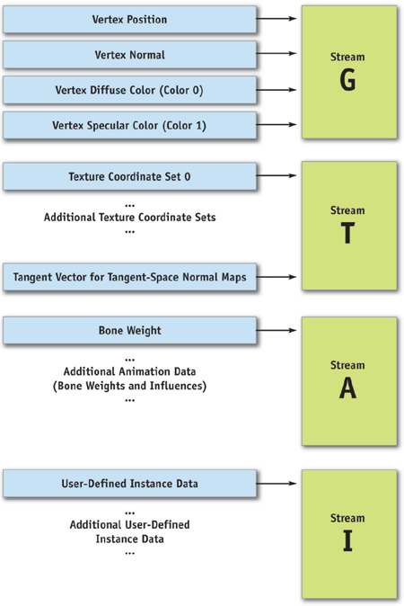
Figure 5-1 Four Types of Vertex Streams
Subsets of these four streams combine to handle different tasks, as shown in Figure 5-2:
-
Render meshes without animation
Possible stream combinations: G or G + T
-
Render meshes with animation
Possible stream combinations: G + A or G + T + A
-
Render instanced meshes (optionally with animation)
Possible stream combinations: G + I or G + T + I
(Optional: G + A + I or G + T + A + I)
-
Render pure z-pass (optionally with or without instancing, with or without animation)
Possible stream combinations: G
(Optional: G + A or G + I or G + A + I)
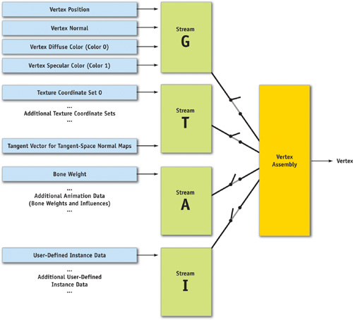
Figure 5-2 Combining Currently Needed Streams
The next section presents an implementation of this model.
5.2 Implementation
Now we show how to implement the abstract concept discussed in Section 5.1. First we examine some multistreaming example code based on DirectX 9.0c. Next we present the resource manager that handles the mesh resources. Finally, we show how to translate generic mesh data into the appropriate hardware structure.
5.2.1 Multistreaming with DirectX 9.0
Microsoft DirectX 8.0 introduced the notion of a stream to bind data to input registers. A stream is a uniform array of component data. Each component consists of one or more elements that represent a single entity, such as position, normal, color, texture coordinate set, and so on. With streams, GPUs are able to perform a direct memory access (DMA) from multiple vertex buffers in parallel. The Direct3D caps bit D3DCAPS9.MaxStreams defines how many streams a GPU supports; modern hardware supports up to 16 streams, while older, DirectX 8.0-compliant GPUs are limited to 8 streams. Because multistreaming has some minor performance implications, it's advisable to minimize the number of active streams. Because our implementation uses only 1 to 4 streams, all GPUs with multistreaming support can be targeted, with minimal loss of performance.
Listing 5-1 shows our multistreaming example code. Using DirectX 9.0 for this task, we need only three simple components:
- A correct vertex declaration (an array of D3DVERTEXELEMENT9) and the IDirect3DDevice9::CreateVertexDeclaration() method to create a vertex declaration object.
- The IDirect3DDevice9::SetVertexDeclaration() method to set the vertex declaration object.
- The IDirect3DDevice9::SetStreamSource() method to bind a vertex buffer to a device data stream, creating an association between the vertex data and one of several data stream ports that feed the primitive processing functions.
Example 5-1. A Set of Vertex Definitions and a Vertex Declaration
//
// Initializations:
//
// Here is a set of vertex definitions to support two streams.
// Vertex format:
//
// stream 0->position + normal + color 0 +color 1
// stream 1->4 texture coordinate pairs
struct VTXSTREAM_0
{
  float fPosX, fPosY, fPosZ;
  float fNormX, fNormY, fNormZ;
  DWORD dwColor0, dwColor1;
};
struct VTXSTREAM_1
{
  float fTexU0, fTexV0;
  float fTexU1, fTexV1;
  float fTexU2, fTexV2;
  float fTexU3, fTexV3;
};
// Vertex declaration
D3DVERTEXELEMENT9 m_VtxDcl[] =
    {
        {0, 0, D3DDECLTYPE_FLOAT3, D3DDECLMETHOD_DEFAULT, D3DDECLUSAGE_POSITION,
         0}, // stream 0, position
        {0, 12, D3DDECLTYPE_FLOAT3, D3DDECLMETHOD_DEFAULT, D3DDECLUSAGE_NORMAL,
         0},
        // stream 0, normal
        {0, 24, D3DDECLTYPE_D3DCOLOR, D3DDECLMETHOD_DEFAULT, D3DDECLUSAGE_COLOR,
         0},
        // stream 0, color 0
        {0, 28, D3DDECLTYPE_D3DCOLOR, D3DDECLMETHOD_DEFAULT, D3DDECLUSAGE_COLOR,
         1},
        // stream 0, color 1
        {1, 0, D3DDECLUSAGE_FLOAT2, D3DDECLMETHOD_DEFAULT,
         D3DDECLUSAGE_TEXCOORD, 0}, // stream 1, tex coord set 0
        {1, 8, D3DDECLUSAGE_FLOAT2, D3DDECLMETHOD_DEFAULT,
         D3DDECLUSAGE_TEXCOORD, 1}, // stream 1, tex coord set 1
        {1, 16, D3DDECLUSAGE_FLOAT2, D3DDECLMETHOD_DEFAULT,
         D3DDECLUSAGE_TEXCOORD, 2}, // stream 1, tex coord set 2
        {1, 24, D3DDECLUSAGE_FLOAT2, D3DDECLMETHOD_DEFAULT,
         D3DDECLUSAGE_TEXCOORD, 3}
        // stream 1, tex coord set 3
}
// Create a vertex declaration object
LPDIRECT3DVERTEXDECLARATION9 m_pVtxDeclObject;
m_pd3dDevice->CreateVertexDeclaration(m_VtxDcl, &m_pVtxDclObj);
In Listing 5-1, we present a set of vertex definitions and create a vertex declaration object m_pVtxDeclObject that describes the following vertex data layout:
- Vertex position data are found in stream 0 with a 0-byte offset. The data type is three-component float that expands to (float, float, float, 1).
- Vertex normal data are found in stream 0 with a 12-byte offset. The data type is three-component float that expands to (float, float, float, 1).
- Diffuse and specular color are found in stream 0 with offsets of 24 bytes (diffuse) and 28 bytes (specular). The data type is four-component, packed, unsigned bytes mapped to a range of 0 to 1.
- Texture coordinate data (sets 0 to 3) are found in stream 1 with offsets of 0 bytes (set 0), 8 bytes (set 1), 16 bytes (set 2), and 24 bytes (set 3). The data type is two-component float that expands to (float, float, 0, 1).
Before calling a draw method, we must set this vertex declaration object together with the vertex buffers bound to the correct device data streams, as shown in Listing 5-2.
Example 5-2. Binding Vertex Buffers to Streams
//
// Each time we want to render primitives:
//
// Set the vertex declaration object
m_pd3dDevice->SetVertexDeclaration(m_pVtxDclObj);
// Bind vertex buffers to device data streams
m_pd3dDevice->SetStreamSource(0, m_pVtxBuf0, 0, sizeof(VTXSTREAM_0));
m_pd3dDevice->SetStreamSource(1, m_pVtxBuf1, 0, sizeof(VTXSTREAM_1));
// Render ..
m_pd3dDevice->DrawIndexedPrimitive(..);
The actual references to the stream data do not occur until a drawing method, such as IDirect3DDevice9::DrawIndexedPrimitive(), is called.
5.2.2 Resource Management
In the Gothic III engine, we employ the concept of resource management to handle the administration of all data-intensive elements, such as vertex data (mesh information), textures, animation data (key frames and skinning data), sounds, and music. All these data structures use a uniform framework. It provides a simple interface so that other systems of the engine can access it.
All resources are packed into abstract data objects. We address these data objects by file name or by a globally unique identifier (GUID). The access of data containers is similarly organized like a database access. If you call a query, you get a referenceable data container with all necessary structures of the specified data.
The resource management system ensures the immediate and simultaneous availability of the data. It is also responsible for converting this proprietary data into the graphics hardware's preferred format.
As we mentioned, the resource management system makes it possible to store mesh data in specified file locations and to load these mesh objects only as needed. These structures must be stored in an efficient and flexible way, but vertex data layout can vary substantially from mesh to mesh.
The loaded resources should provide a reference counter, so that the same mesh can be used repeatedly in a scene. Geometry instancing is used to speed up rendering this type of mesh. (See Chapter 3 of this book, "Inside Geometry Instancing.")
The mesh information is generated by tools such as 3ds max or Maya. For this operation, a suitable importer has to be developed, as shown in Figure 5-3.
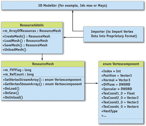
Figure 5-3 Structure of the Resource Framework
The Mesh Resource
One of the database containers provided by the resource management system is a mesh resource, which has all relevant structures, all vertex and index data arrays, and a link to an abstract material object (which is also a referenceable resource).
Note that the vertex structure wrapped into a resource class (as shown in Figure 5-3) isn't adapted to any specific graphics API (such as DirectX or OpenGL). We can therefore implement the whole resource system independent of the graphics API used.
These structures consist of simple vertex streams (arrays) containing a single vertex component, such as position (an array of 3D vectors), normals (an array of 3D vectors), color (an array of DWORD values), or up to 16 texture coordinates (an array of 1D, 2D, 3D, or 4D vectors) and other customized data arrays such as weights for hardware skinning.
To complete this groundwork, we have developed a hardware-independent resource framework with a mesh class and its administrative interface. Furthermore, we have written a specified importer for the corresponding modeling tool.
5.2.3 Processing Vertices
The renderer takes over the task of changing the hardware-independent data into a format that is optimal for the graphics hardware.
First, the mesh resources are loaded into main memory at the start of the application. Alternatively, we use an on-demand approach to load the data into memory when needed, using a separate thread.
For the renderer, the mesh object is only a temporary container to build up the correct format. The generated hardware-dependent format is used by the application to draw the scene. The reason for this strict separation is the ability to tailor the data optimally for the GPU found in the PC on which the application is currently running. We use only the vertex data that are actually needed.
This separation becomes useful in the adaptation of needed texture coordinates: On less powerful hardware, many visual effects are turned off because the hardware is incapable of running them, or because the overall rendering load needs to be reduced. Because these effects are not rendered, the texture coordinates used by these effects need not be passed to the graphics hardware. They can simply be removed. So we reduce memory consumption and save processor power and bandwidth.
For this task, we provide a submodule, which we have named Vertexprocessor, that translates the generic mesh data into the specified hardware structure. The following steps are necessary for the data to be prepared for multistreaming:
- When a mesh resource is requested, Vertexprocessor loads this data into memory if the object isn't already available, or increments the reference counter of the mesh object if it is already loaded.
- The stored vertex format of the mesh object is determined. This can happen via the embedded FVF flag or with the implementation used in the resource class (hardware independent).
- The Vertexprocessor divides the single generic vertex arrays into the four hardware-specific vertex streams (that is, streams G, T, A, and I, discussed in Section 5.1). The vertex arrays are accessed by the MeshResource::GetVertexStreamArray() method, as shown in Figure 5-4, which translates or copies the arrays into the specific component of one of the four vertex buffers.
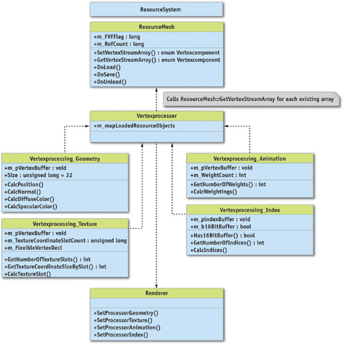
Figure 5-4 Query of Single Vertex Streams Used by Vertexprocessor
Geometry Data
The Vertexprocessor unit for geometry data seeks position, normals, and the two colors (if available) from a mesh object.
For illustration purposes, Listing 5-3 creates a vertex buffer that contains all this information and uses this specific vertex layout. The buffer should have a cache-friendly size of 32 bytes per entry, so the layout is fixed for this buffer type.
Example 5-3. Creating a Vertex Buffer
D3DVERTEXELEMENT9 m_VtxDcl[] = {
    {0, 0, D3DDECLTYPE_FLOAT3, D3DDECLMETHOD_DEFAULT, D3DDECLUSAGE_POSITION,
     0}, // stream 0, position
    {0, 12, D3DDECLTYPE_FLOAT3, D3DDECLMETHOD_DEFAULT, D3DDECLUSAGE_NORMAL, 0},
    // stream 0, normal
    {0, 24, D3DDECLTYPE_D3DCOLOR, D3DDECLMETHOD_DEFAULT, D3DDECLUSAGE_COLOR, 0},
    // stream 0, color 0
    {0, 28, D3DDECLTYPE_D3DCOLOR, D3DDECLMETHOD_DEFAULT, D3DDECLUSAGE_COLOR, 0},
    // stream 0, color 1
};
// Here comes the vertex definition.
// Vertex format:
// stream 0->position + normal + color 0 + color 1
struct sVTXStreamGeometry
{
  float vecPos[3];
  float vecNorm[3];
  DWORD dwColor0, dwColor1;
};
// Data container Resourcemesh supports GetVertexStreamArray here.
// (See API methods above.)
cResourceMesh *m_pResourceMesh;
// Create the vertex declaration and create a specific vertex buffer.
// For clarity, we calculate the size of the buffer in the number of
// elements and the corresponding FVF flags. In our engine implementation,
// the geometry stream has a size of 32 bytes (cache-friendly), so we
// can easily create the sufficient memory size of the vertex buffer.
CreateVertexDeclaration(m_VtxDcl);
m_pVtxBuf0 = CreateVertexBuffer(NumVertices, FVF_XYZ | FVF_NORMAL |
                                                 FVF_DIFFUSE | FVF_SPECULAR);
sVTXStreamGeometry *pBuffer = LockBuffer(m_pVtxBuf0);
for each
  vertexIndex in m_pResourceMesh
  {
    pBuffer->m_vecPos =
        m_pResourceMesh->GetVertexStreamArray(enum_Position, vertexIndex);
    pBuffer->m_vecNorm =
        m_pResourceMesh->GetVertexStreamArray(enum_Normal, vertexIndex);
    pBuffer->m_dwColor0 =
        m_pResourceMesh->GetVertexStreamArray(enum_Diffuse, vertexIndex);
    pBuffer->m_dwColor1 =
        m_pResourceMesh->GetVertexStreamArray(enum_Specular, vertexIndex);
    pBuffer++;
  }
Texture Data
The Vertexprocessor unit for texture data fetches the available texture coordinate slots from the mesh object and builds up a flexible vertex buffer with all necessary texture coordinates. At most, eight texture coordinate groups (with a 1D, 2D, 3D, or 4D vector per texture coordinate) are possible.
In addition, one of the slots can be encoded as tangent vectors for tangent-space normal maps; otherwise, it would be necessary to use a separate vertex buffer stream for this information. We omit this in Listing 5-4 for clarity. It is, however, straightforward to add this feature.
If light maps are available, we should use a separate Vertexprocessor unit (that is, a separate vertex buffer per mesh instance), because every instance must have unique UV pairs for light map textures. Light maps must be individually mapped, and their mapping coordinates depend on their world-space position, and so they can't be instantiated. This can be a big problem for the memory footprint and performance of your application. Consequently, light maps are useful for big meshes, such as terrain in outdoor scenarios or irregular wall meshes in dungeons, but not for small meshes or multi-instantiated objects.
Example 5-4. A Vertex Buffer Stream for Texture Data
// Data container Resourcemesh supports GetVertexStreamArray here.
// (See API methods above.)
cResourceMesh *m_pResourceMesh;
// This is a template array structure to allocate a flexible amount
// of vtxDcl structures in one block
Array<D3DVERTEXELEMENT9> arrDeclVtx;
// We create a specific vertex buffer for textures. We use the FVF flag
// from Resourcemesh and filter the specific texture flags to create
// the specific buffer.
// For clarity, we use here a function that calculates the size of the
// buffer and the corresponding FVF flags. You can use an alternative
// implementation to calculate the correct size of the vertex buffer.
sVTXStreamTexture *pVtxBuf1 = CreateVertexBuffer(
    NumTextureEntries, m_pResourceMesh->m_FVFFlag &TextureFlags);
// Lock buffer with unspecific byte pointer
char *pBuffer = LockBuffer(pVtxBuf1);
// Current buffer position (in bytes) in locked data of vertex buffer
DWORD dwGlobalBufferPosition = 0;
for each
  textureIndex in m_pResourceMesh
  {
    DWORD dwCurrentOffset = 0; // Current offset position for vtxDecl
    for (int i = 0; i < m_pResourceMesh->GetNumberOfTextureSlots(); i++)
    {
      // Array template allocates us a new structure at the end of the
      // structure block and returns a nonconstant reference of the block.
      // All structures allocated before remain unchanged (by realloc).
      D3DVERTEXELEMENT9 &flexibleElement = arrDeclVtx.InsertNewEnd();
      flexibleElement.Stream = 1; // Is at 2nd position after Geometry
      flexibleElement.Usage = D3DDECLUSAGE_TEXCOORD;
      // Current size in bytes of texture slots (u,v = 8 bytes)
      // r,s,t = 12 bytes, r,s,t,w = 16 bytes
      DWORD dwCurrentTextureSlotSize =
          m_pResourceMesh->GetTextureCoordinateSizeBySlot(i);
      // For specified slot, we look for what size (in bytes) we need
      // and add it to our global offset counter dwCurrentOffset
      flexibleElement.Offset = dwCurrentOffset;
      // Calculate stream position in Resourcemesh for specified
      // texture slot
      int enumStreamArraySlot = m_pResourceMesh->GetTextureSlotEnum(i);
      // Now copy out the vertex information from the Resourcemesh
      // stream into locked buffer
      memcpy(&pBuffer[dwGlobalBufferPosition + dwCurrentOffset],
             m_pResourceMesh->GetVertexStreamArray(enumStreamArraySlot,
                                                   textureindex),
             dwCurrentTextureSlotSize);
      dwCurrentOffset += dwCurrentTextureSlotSize;
      // Calculate types of vtxDecl (D3DDECLTYPE_FLOAT2 = 8 bytes,
      // D3DDECLTYPE_FLOAT3 = 12 bytes, D3DDECLTYPE_FLOAT4 = 16 bytes)
      flexibleElement.Type = CalculateDataSizeType(dwCurrentTextureSlotSize);
    }
    // Add new position offset to global position in buffer
    dwGlobalBufferPosition += dwCurrentOffset;
  }
Animation Data
The Vertexprocessor unit for animation data builds up weights for animation skinning with bones in hardware. A varying number of weights per bone can be used, so it is not necessary to waste more memory than is really needed. In Gothic III, we use up to six weights per bone for our animation system.
Index Data
An index buffer corresponding to the above vertex buffers is also built up. Indices are stored into a mesh object as a separate stream of information. The bit size of index entries (whether 16 or 32 bit) depends on the number of vertices. Having more than 65,535 entries necessitates using DWORDs as index entries. Otherwise, WORD (16-bit) indices suffice. Choosing the smallest possible data type helps reduce an application's memory footprint.
The Vertexprocessor has the responsibility to create all the previously described vertex buffers in an optimal manner for hardware (typically they are created as Pool_Managed and WriteOnly)(Ashida 2004).
Rendering the Streams
Once all the streams are built up properly, they are available for rendering and drawing.
As an example of using streams separately, we execute the G-stream (that is, the geometry stream) as a separate z-pass, to achieve fast z-rejects in hardware and to use this buffer in conjunction with an occlusion query system implemented in the render system. (See Chapter 6 of this book, "Hardware Occlusion Queries Made Useful," for an example of such a system.)
It is possible to add the A-stream (the animation stream) in the calculation, but the effort isn't worthwhile in most cases. The number of pixels that differ because of the animation is typically small and thus out of proportion to the additional rendering cost of adding animation.
Individual streams are activated depending on the view (whether solid rendering or z-pass) by the renderer.
5.3 Conclusion
In this chapter, we have shown how current applications can overcome problems caused by the growing amount of geometry data in scenes. We've discussed a flexible model that gives the application more control over the data and drives the detected hardware optimally by combining two powerful techniques:
- Several vertex buffers are combined via multistreaming.
- Each vertex buffer is controlled by an optimized resource manager.
A nice side benefit: we efficiently handle the bandwidth for data, which sometimes can be limited because of data duplication/redundant data transmission across the bus from system memory to the GPU.
5.4 References
Ashida, Koji. 2004. "Optimising the Graphics Pipeline." NVIDIA presentation. http://developer.nvidia.com/docs/IO/10878/ChinaJoy2004_OptimizationAndTools.pdf
Cebenoyan, Cem. 2004. "Graphics Pipeline Performance." In GPU Gems, edited by Randima Fernando, pp. 473–486. Addison-Wesley. Available online at http://developer.nvidia.com/object/GPU_Gems_Samples.html
For additional information about programming one or more streams in DirectX, see the Microsoft Web site:
http://msdn.microsoft.com/directx
Copyright
Many of the designations used by manufacturers and sellers to distinguish their products are claimed as trademarks. Where those designations appear in this book, and Addison-Wesley was aware of a trademark claim, the designations have been printed with initial capital letters or in all capitals.
The authors and publisher have taken care in the preparation of this book, but make no expressed or implied warranty of any kind and assume no responsibility for errors or omissions. No liability is assumed for incidental or consequential damages in connection with or arising out of the use of the information or programs contained herein.
NVIDIA makes no warranty or representation that the techniques described herein are free from any Intellectual Property claims. The reader assumes all risk of any such claims based on his or her use of these techniques.
The publisher offers excellent discounts on this book when ordered in quantity for bulk purchases or special sales, which may include electronic versions and/or custom covers and content particular to your business, training goals, marketing focus, and branding interests. For more information, please contact:
U.S. Corporate and Government Sales
(800) 382-3419
corpsales@pearsontechgroup.com
For sales outside of the U.S., please contact:
International Sales
international@pearsoned.com
Visit Addison-Wesley on the Web: www.awprofessional.com
Library of Congress Cataloging-in-Publication Data
GPU gems 2 : programming techniques for high-performance graphics and general-purpose
computation / edited by Matt Pharr ; Randima Fernando, series editor.
p. cm.
Includes bibliographical references and index.
ISBN 0-321-33559-7 (hardcover : alk. paper)
1. Computer graphics. 2. Real-time programming. I. Pharr, Matt. II. Fernando, Randima.
T385.G688 2005
006.66—dc22
2004030181
GeForce™ and NVIDIA Quadro® are trademarks or registered trademarks of NVIDIA Corporation.
Nalu, Timbury, and Clear Sailing images © 2004 NVIDIA Corporation.
mental images and mental ray are trademarks or registered trademarks of mental images, GmbH.
Copyright © 2005 by NVIDIA Corporation.
All rights reserved. No part of this publication may be reproduced, stored in a retrieval system, or transmitted, in any form, or by any means, electronic, mechanical, photocopying, recording, or otherwise, without the prior consent of the publisher. Printed in the United States of America. Published simultaneously in Canada.
For information on obtaining permission for use of material from this work, please submit a written request to:
Pearson Education, Inc.
Rights and Contracts Department
One Lake Street
Upper Saddle River, NJ 07458
Text printed in the United States on recycled paper at Quebecor World Taunton in Taunton, Massachusetts.
Second printing, April 2005
Dedication
To everyone striving to make today's best computer graphics look primitive tomorrow
- Copyright
- Inside Back Cover
- Inside Front Cover
- Part I: Geometric Complexity
-
- Chapter 1. Toward Photorealism in Virtual Botany
- Chapter 2. Terrain Rendering Using GPU-Based Geometry Clipmaps
- Chapter 3. Inside Geometry Instancing
- Chapter 4. Segment Buffering
- Chapter 5. Optimizing Resource Management with Multistreaming
- Chapter 6. Hardware Occlusion Queries Made Useful
- Chapter 7. Adaptive Tessellation of Subdivision Surfaces with Displacement Mapping
- Chapter 8. Per-Pixel Displacement Mapping with Distance Functions
- Part II: Shading, Lighting, and Shadows
-
- Chapter 9. Deferred Shading in S.T.A.L.K.E.R.
- Chapter 10. Real-Time Computation of Dynamic Irradiance Environment Maps
- Chapter 11. Approximate Bidirectional Texture Functions
- Chapter 12. Tile-Based Texture Mapping
- Chapter 13. Implementing the mental images Phenomena Renderer on the GPU
- Chapter 14. Dynamic Ambient Occlusion and Indirect Lighting
- Chapter 15. Blueprint Rendering and "Sketchy Drawings"
- Chapter 16. Accurate Atmospheric Scattering
- Chapter 17. Efficient Soft-Edged Shadows Using Pixel Shader Branching
- Chapter 18. Using Vertex Texture Displacement for Realistic Water Rendering
- Chapter 19. Generic Refraction Simulation
- Part III: High-Quality Rendering
-
- Chapter 20. Fast Third-Order Texture Filtering
- Chapter 21. High-Quality Antialiased Rasterization
- Chapter 22. Fast Prefiltered Lines
- Chapter 23. Hair Animation and Rendering in the Nalu Demo
- Chapter 24. Using Lookup Tables to Accelerate Color Transformations
- Chapter 25. GPU Image Processing in Apple's Motion
- Chapter 26. Implementing Improved Perlin Noise
- Chapter 27. Advanced High-Quality Filtering
- Chapter 28. Mipmap-Level Measurement
- Part IV: General-Purpose Computation on GPUS: A Primer
-
- Chapter 29. Streaming Architectures and Technology Trends
- Chapter 30. The GeForce 6 Series GPU Architecture
- Chapter 31. Mapping Computational Concepts to GPUs
- Chapter 32. Taking the Plunge into GPU Computing
- Chapter 33. Implementing Efficient Parallel Data Structures on GPUs
- Chapter 34. GPU Flow-Control Idioms
- Chapter 35. GPU Program Optimization
- Chapter 36. Stream Reduction Operations for GPGPU Applications
- Part V: Image-Oriented Computing
-
- Chapter 37. Octree Textures on the GPU
- Chapter 38. High-Quality Global Illumination Rendering Using Rasterization
- Chapter 39. Global Illumination Using Progressive Refinement Radiosity
- Chapter 40. Computer Vision on the GPU
- Chapter 41. Deferred Filtering: Rendering from Difficult Data Formats
- Chapter 42. Conservative Rasterization
- Part VI: Simulation and Numerical Algorithms
-
- Chapter 43. GPU Computing for Protein Structure Prediction
- Chapter 44. A GPU Framework for Solving Systems of Linear Equations
- Chapter 45. Options Pricing on the GPU
- Chapter 46. Improved GPU Sorting
- Chapter 47. Flow Simulation with Complex Boundaries
- Chapter 48. Medical Image Reconstruction with the FFT