
GPU Gems
GPU Gems is now available, right here, online. You can purchase a beautifully printed version of this book, and others in the series, at a 30% discount courtesy of InformIT and Addison-Wesley.
The CD content, including demos and content, is available on the web and for download.
Chapter 9. Efficient Shadow Volume Rendering
Morgan McGuire
Brown University
9.1 Introduction
A security guard's shadow precedes him into a vault—enough advance warning to let the thief hide on the ceiling. Ready to pounce on an unwary space marine, the alien predator clings to a wall, concealed in the shadow of a nearby gun turret. Yellow and red shadows of ancient marbled gods flicker on the walls of a tomb when the knight's torch and the druid's staff illuminate the statues inside. These are just a few vivid examples of how real-time shadows are used today in gaming.
Real-time shadows are now required for new 3D games. Gamers are accustomed to the perceptual, strategic, and cinematic benefits of realistic lighting. Unlike other effects, shadows aren't rendered objects. Instead, they are areas of the screen that are darker than others because they receive less light during illumination calculations. The hard part of adding shadows to a rendering engine is finding those areas in real time. This chapter describes how to use shadow volumes, the shadowing method used in games such as id Software's Doom 3, to mark shadowed pixels in the stencil buffer. See Figure 9-1. Once each pixel is classified as shadowed or illuminated, it's simple to modify the pixel program responsible for lighting in order to zero out the illumination contribution at shadowed pixels.
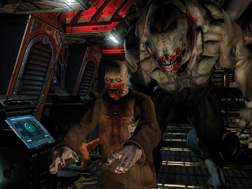
Figure 9-1 A Scene from id Software's
9.1.1 Where to Use Shadow Volumes
The shadow volume technique creates sharp, per-pixel accurate shadows from point, spot, and directional lights. A single object can be lit by multiple lights, and the lights can have arbitrary colors and attenuation. The shadows are cast from triangle meshes onto whatever is in the depth buffer. This means that the objects being shadowed can be meshes, billboards, particle systems, or even prerendered scenes with depth buffers.
Compared to other algorithms, shadow volumes can handle many difficult-to-shadow scenes well. Figure 9-2 shows one such problematic scene. The only light source is a point light inside the jack-o'-lantern. The entire scene is in shadow except for the triangular patches of ground illuminated by light that shines out through the holes in the pumpkin. This is a hard case for several reasons. It inverts our usual assumption that most of the scene is lit and shadows are small—rarely do shadows enclose the entire scene. The lit areas are very large compared to the holes in the pumpkin that create them. Although light shines out through only the front and the bottom, the light is omnidirectional and shadows must be considered from all angles. Finally, the shadow caster is more than close to the light source: it surrounds it.
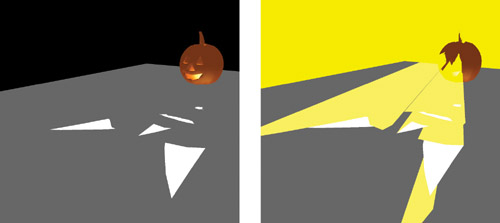
Figure 9-2 A Difficult Scene for Shadows: Light Inside a Jack-o'-Lantern
Shadow volumes are not ideal for all scenes. The technique involves constructing a 3D volume that encloses all shadows cast by an object. This volume is constructed from the shadow caster's mesh; however, some shadow casters do not have a mesh that accurately represents their shape. Examples include a billboard, a particle system, or a mesh textured with an alpha matte (such as a tree leaf). These casters produce shadows based on their actual meshes, which do not match how the objects really appear. For example, a billboard smoke cloud casts a rectangular shadow.
Another problem object is a mesh containing edges that have only a single adjacent face, commonly known as a crack. In the real world, if you look into a crack, you see the inside of the object. Of course, in a rendering engine, you'll see through the object and out the other side because the inside is lined with back-facing polygons culled during rendering. This object is nonsensical as a shadow caster. From some angles, it casts a solid shadow; from other angles, light peeks through the hole and shines out the other side. Even worse, an optimization for the shadow volume breaks when using these objects, creating a large streak of darkness hanging in empty space, as shown in Figure 9-3.
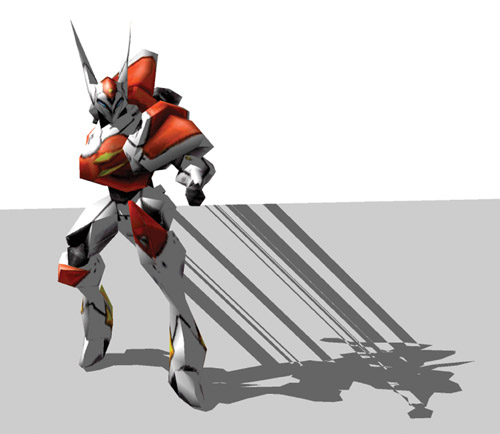
Figure 9-3 Cracks in a Model Let Shadows "Leak" Through the Air
Another potential limitation of the approach is that it requires that everything in a scene cast shadows. When a character's shadow is cast on a wall, it is also cast on everything behind the wall. The only reason the viewer doesn't see the shadow on the other side of the wall is that the wall casts its own shadow that overlaps it. If you cast shadows from characters but not from scene geometry, the shadows appear to go through solid objects.
The ideal scene for shadow volume performance is a top view, such as those found in many real-time strategy, sports, and above-ground adventure games. Such a scene is lit from a few downward-pointing directional lights, and the camera is above all the objects, looking down at the ground. The worst case for performance is a scene with multiple point lights in the middle of a large number of shadow-casting objects—such as a large party of torch-wielding adventurers in an underground room with pillars.
9.2 Program Structure
The shadow volume technique consists of two parts: constructing the volumes from silhouette edges and rendering them into the stencil buffer. These parts are repeated for each light source, and the resulting images are added together to create a final frame (a process called multipass rendering). The basic algorithm is easy to understand and implement, but it is slow for big scenes. To address this, a series of optimizations reduces the geometry-processing and fill-rate requirements.
We begin with a high-level view of the program structure. We follow up with a detailed discussion of each step, and then we look at several optimizations. Finally, we peek into the future by examining several research projects on shadow volumes.
9.2.1 Multipass Rendering
Mathematically, the illumination at a point is the sum of several terms. We see this in the Phong illumination equation for a single light, which is the sum of ambient, emissive (internal glow), diffuse, and specular components. A scene with multiple lights has a single ambient term and a single emissive term, but it has one diffuse term and one specular term for each light. When rendering without shadows, multiple lights can all be rendered in a single pass. This is typically done by enabling multiple hardware light sources or implementing a pixel shader with code for each light.
When rendering with shadows, the contribution from a given light is zero at some points because those points are shadowed. To account for this, the diffuse and specular contribution from each light is computed in a separate rendering pass. The final image is the sum of an initial pass that computes ambient and emissive illumination and the individual lighting passes. Because the initial pass writes depth values into the z-buffer, the additional passes have zero overdraw and can be substantially cheaper in terms of fill rate. Objects rendered in the additional passes are also good candidates for occlusion culling.
Although shadow volumes do not create the soft shadows cast by area sources, multiple passes can be exploited to create a similar effect by distributing multiple, dim spotlights over the surface of an area light. Unfortunately, for a complex scene having enough lights to make this look good, this method is too slow to be practical. (A new research technique, described in Assarsson et al. 2003, suggests a more efficient way of rendering soft shadows with shadow volumes.)
The individual lighting passes are combined using alpha blending. To do this, render the ambient/emissive pass to the back buffer with depth writing enabled and the blending function set to glBlendFunc(GL_ONE, GL_ZERO). This initializes the depth buffer and creates the base illumination.
Then for the light passes, disable depth writing and change the blending function to glBlendFunc(GL_ONE, GL_ONE). This blending mode adds newly rendered pixels to the ones already there. The pre-initialized depth buffer prevents overdraw. Also, be sure to set the depth test to glDepthFunc(GL_LEQUAL) to avoid z-fighting between subsequent passes.
With these settings, make one pass for each light source. Each pass clears the stencil buffer, marks shadowed areas in it, and then computes the illumination in nonshadowed areas and adds them to the frame buffer.
The overall structure of the rendering part of the program is shown in Figure 9-4.
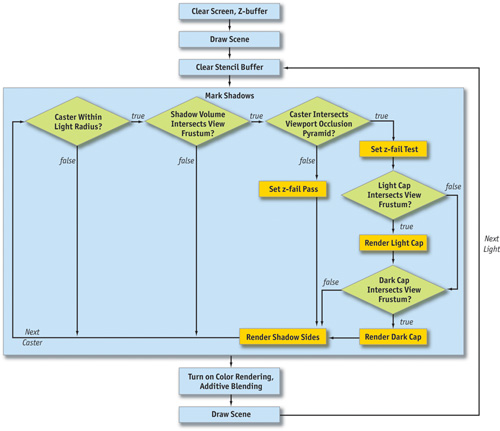
Figure 9-4 Program Structure Diagram
A simplified version of this procedure appears in Listing 9-1. The simplification is that the "mark shadows" step is reduced to the worst case, in which every one of the conditionals in the diagram returns true. After walking through the code in detail, we'll put the shorter paths back in as optimizations. The sections of code that will be changed by these optimizations are highlighted to make them easy to find later.
Example 9-1. Program Structure Pseudocode
static const float black[] = {0.0f, 0.0f, 0.0f, 0.0f};
glPushAttrib(GL_ALL_ATTRIB_BITS);
setupCamera();
// -- Ambient + emissive pass --
// Clear depth and color buffers
glClear(GL_DEPTH_BUFFER_BIT | GL_COLOR_BUFFER_BIT);
glBlendFunc(GL_ONE, GL_ZERO);
glEnable(GL_BLEND_FUNC);
glDepthMask(0xFF);
glDepthFunc(GL_LEQUAL);
glEnable(GL_LIGHTING);
glDisable(GL_LIGHT0);
glLightModelfv(LIGHT_MODEL_AMBIENT, globalAmbient);
drawScene();
// Light passes
glLightModelfv(LIGHT_MODEL_AMBIENT, black);
glEnable(GL_LIGHT0);
glBlend(GL_ONE, GL_ZERO);
glDepthMask(0x00);
glEnable(GL_LIGHT0);
glEnable(GL_STENCIL_TEST);
glEnable(GL_STENCIL_TEST_TWO_SIDE_EXT);
for (int i = numLights - 1; i > = 0; --i)
{
  // (The "XY" clipping optimizations set the scissor
  // region here.)
  //-- Mark shadows from all casters --
  // Clear stencil buffer and switch to stencil-only rendering
  glClear(GL_STENCIL_BUFFER_BIT);
  glColorMask(0, 0, 0, 0);
  glDisable(GL_LIGHTING);
  glStencilFunc(GL_ALWAYS, 0, ~0);
  glStencilMask(~0);
  loadVertexShader();
  for (int c = 0; c < numCasters; ++c)
  {
    // (The "point and spot" optimization marks shadows
    // only for casters inside the light's range)
    setVertexParam("L", object->cframe.inv() * light[i]);
    object[c]->markShadows(light[i].direction);
  }
  unloadVertexShader();
  //-- Add illumination -
  // Configure lighting
  configureLight(light[i]);
  glEnable(GL_LIGHTING);
  glStencilFunc(GL_EQUAL, 0, ~0);
  glActiveStencilFaceEXT(GL_FRONT);
  glStencilOp(GL_KEEP, GL_KEEP, GL_KEEP);
  glActiveStencilFaceEXT(GL_BACK);
  glStencilOp(GL_KEEP, GL_KEEP, GL_KEEP);
  glDepthFunc(GL_EQUAL);
  glColorMask(1, 1, 1, 1);
  glCullFace(GL_BACK);
  // (The "point and spot" optimization adds illumination
  // only for objects inside the light's range)
  drawScene();
}
glPopAttrib();
9.2.2 Vertex Buffer Structure
The shadow of a mesh is cast by its silhouette. To quickly find the silhouette edges and extrude them into a shadow volume, meshes need more information than what's needed in a traditional rendering framework that uses only face triangles.
In our system, the vertex buffer for a mesh contains two copies of each vertex. Say there are n original vertices. Elements 0 through n - 1 of the vertex buffer contain typical vertices, of the form (x, y, z, 1). Elements n through 2n - 1 are copies of the first set but have the form (x, y, z, 0). The first set can be used for normal rendering. Both sets will be used for shadow determination, where a vertex shader will transform the second set to infinity.
Objects also must have adjacency information and per-face normals. For every face, we need to know the three counterclockwise vertex indices and the surface normal. For every edge, we need the indices of the two adjacent faces and the indices of the two vertices. As mentioned previously, the model must be closed so it has no cracks. In terms of adjacency information, this means that every edge has exactly two adjacent faces that contain the same vertices but in opposite order. By convention, let the first face index of an edge be the one in which the edge vertices are traversed in order, and let the second index be the face in which the vertices are traversed in the opposite order. Note that there may be vertices in the model that are not in any edge or face. This is because it is a common practice when creating 3D models to collocate vertices with different texture coordinates. For adjacency information, we care only about the raw geometry and ignore the texture coordinates, normals, vertex colors, and so on that are stored with a model for rendering purposes.
9.2.3 Working at Infinity
Unlike other OpenGL programs you may have written, shadow volumes make extensive use of coordinates at infinity. Shadow volumes themselves consist of both finite geometry and geometry at infinity. The algorithm is implemented for point light sources, and directional lights are handled as point lights at infinity. The far clipping plane must be at infinity so that it will not cut off the infinite shadow volumes, and the perspective projection must be configured to take this into account.
OpenGL provides full support for working at infinity using homogeneous coordinates. This section reviews homogeneous vertices (for geometry and light sources) and shows how to configure an infinite-perspective matrix.
Finite homogeneous points are represented as (x, y, z, 1); that is, the w
component is equal to 1. This implicitly means the point at 3D position (x/1, y/1, z/1).
Perspective projection matrices use the w component to divide through by a nonunit value, creating
vertices such as (x, y, z, -z) that become (x/-z,
y/-z, -1) after the homogeneous divide. What happens when the w component is zero? We
get a point that has the form (x/0, y/0, z/0). This point is "at infinity." Of
course, if we actually divided each component by 0 and computed the point, it would become
( ,
,
),
which throws away important information—the direction in which the point went to infinity. The (x,
y, z, 0) representation uses w = 0 to flag the point as "at infinity" but retains the
directional information (x, y, z).
,
,
),
which throws away important information—the direction in which the point went to infinity. The (x,
y, z, 0) representation uses w = 0 to flag the point as "at infinity" but retains the
directional information (x, y, z).
Intuitively, a point at infinity acts as if it is very far away, regardless of the physical dimensions of the scene. Like stars in the night sky, points at infinity stay fixed as the viewer's position changes, but they rotate according to the viewer's orientation. OpenGL renders points with w = 0 correctly. Again like stars, they appear as if rendered on a sphere "at infinity" centered on the viewer. Note that for a point at infinity, only the direction (x, y, z) is important, not the magnitude of the individual components. It is not surprising that OpenGL therefore uses w = 0 to represent a directional light as a point light whose position is the vector to the light: a directional light is a point light that has been moved to infinity along a specific direction.
Throughout this chapter, we use w = 0 to represent points at infinity. We'll not only use point lights at infinity, but also extrude shadow volumes to infinity. In the previous section, we used w = 0 as a notation in the second half of the vertex buffer. This was because those vertices will be moved to infinity (they are the infinite end of the shadow volume). The vertex shader will move them relative to the light before they are actually transformed to infinity, however.
When rendering all of these objects at infinity, we can't have them clipped by the far plane. Therefore, we need to move the far clipping plane to infinity. This is done by computing the limit of the standard projection matrix as the far plane moves to infinity:
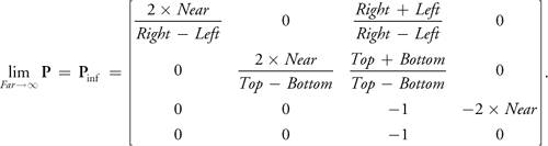
In code, this is a minor change to the way we compute the perspective projection matrix. Just create the projection matrix as shown in Listing 9-2 instead of using glFrustum.
Example 9-2. An Infinite Projection Matrix in the Style of glFrustum
void perspectiveProjectionMatrix(double left, double right, double bottom,
                                 double top, double nearval, double farval)
{
  double x, y, a, b, c, d;
  x = (2.0 * nearval) / (right - left);
  y = (2.0 * nearval) / (top - bottom);
  a = (right + left) / (right - left);
  b = (top + bottom) / (top - bottom);
  if ((float)farval > = (float)inf)
  {
    // Infinite view frustum
    c = -1.0;
    d = -2.0 * nearval;
  }
  else
  {
    c = -(farval + nearval) / (farval - nearval);
    d = -(2.0 * farval * nearval) / (farval - nearval);
  }
  double m[] = {x, 0, 0, 0, 0, y, 0, 0, a, b, c, -1, 0, 0, d, 0};
  glLoadMatrixd(m);
}
The Cg vertex shader from Listing 9-3 transforms points with w = 1 normally and sends points with w = 0 to infinity away from the light.
Example 9-3. A Vertex Shader for Extruding w = 0 Vertices Away from the Light
VOut main(const float4x4 uniform in MVP, const float4 uniform in L,
          const VIn in vin)
{
  VOut vout; // (The "directional" optimization eliminates the vertex shader
  // by using different rendering loops for point and directional
  // lights.)
  vout.pos = MVP * (vin.pos.w == 0 ? float4(vin.pos.xyz * L.w - L.xyz, 0)
                                   : vin.posvin.pos);
  return vout;
}
The branch operator (?) can be replaced with a call to the lerp function on older graphics cards that don't support branching in vertex shaders. Note that multiplying the point position by L.w in the middle line makes the point's position irrelevant for a directional light. This is because the vector from the light to a point is independent of the point position for a directional light. In Listing 9-1, the call to setVertexParam sets the object-space light vector. The implementations of loadVertexProgram, unloadVertexProgram, and setVertexParam depend on the vertex shader runtime used.
9.3 Detailed Discussion
The goal of markShadows is to set the stencil buffer to zero for illuminated pixels and to a nonzero number for shadowed pixels. It does this by constructing a shadow volume—the geometry that bounds the shadow regions—and rendering it into the stencil buffer. Here we briefly look at the mathematical justification for this, and then we cover the implementation in detail.
9.3.1 The Math
Figure 9-5 shows a simple scene with a single point light (the light bulb icon), a shadow-casting box, a shadow-receiving ground plane, and a viewer on the left. The line in front of the viewer represents the image plane, which is important to the discussion in Section 9.5. The blue arrows represent light rays from the source (for clarity, only a few are shown). The ground plane is bright where the leftmost and rightmost rays strike it. The center rays hit the shadow caster instead and are blocked. The ground plane is dark (shadowed) underneath the caster where these rays are blocked. Somewhere between the outer and the inner rays in the diagram are critical lines, shown dashed. These lines mark the edges of the shadow. Note that they pass through the center of the light and the edges of the shadow caster. The diagram is 2D; in 3D, these are not lines but quadrilaterals. These lines are the sides of the shadow volume. Everything farther than the shadow caster and between them is shadowed. All other points are illuminated.
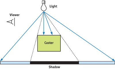
Figure 9-5 A Simple Scene
Figure 9-6 shows the shadow volume explicitly. The shadow volume has three pieces.
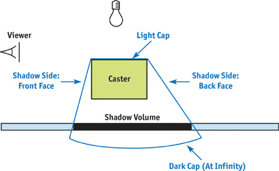
Figure 9-6 Shadow Volume for the Simple Scene
- The sides are constructed by extruding the edges of the caster away to infinity to form quads. Objects between the caster and the light should not be shadowed, so we have to close the volume on the top. Because an object casts the same shadow as its silhouette, we need to extrude only the silhouette edges. These are edges where, from the point of view of the light, one adjacent face is a back face (N · L < 0) and one adjacent face is a front face (N · L > 0).
- The light cap is the geometry that closes the volume on the side near the light. It is composed of the caster's light front-facing polygons (that is, polygons that are front faces from the light's point of view). Shadows extend infinitely away from the light, but mathematically we have to close the geometry at the back end to make it a volume.
- The dark cap is composed of the caster's light back-facing polygons (that is, polygons that are back faces from the light's point of view) expanded to infinity. In Figure 9-6, they are shown as a curve, because polygons at infinity can be thought of as lying on a very large sphere surrounding the entire scene.
Although the figures show a 2D diagram of a simple scene, keep in mind that the shadow volumes are in 3D and may have complicated geometry if the shadow caster has a complicated shape. For comparison, the geometry of real 3D shadow volumes is shown in Figures 9-2, 9-7, and 9-10. If there are multiple shadow casters (and there usually are), the shadow volume will have many separate parts. These parts might even overlap. None of this is a problem; the algorithm handles a triangle or a complete scene equally well without any special work on our part.
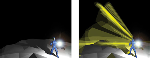
Figure 9-7 A Shadowed Character from
Here's a mathematical strategy for performing shadow determination using the shadow volume. When rendering, each pixel corresponds to a point in 3D space. We want to set the stencil buffer to a nonzero value (shadowed) at that pixel if the point is inside the shadow volume; otherwise, we'll set it to zero (illuminated). Call the point in question P. Consider intersections between the ray that starts at P and travels to infinity along the negative view vector, -V, and the shadow volume. There are two kinds of intersections. An entering intersection occurs when the ray moves from outside the shadow volume to inside. Let M be the surface normal to the shadow face intersected. At an entering intersection, M · V > 0. An exiting intersection occurs when the ray leaves a shadow volume and has M · V < 0 (ignore glancing intersections where M · V = 0). The key idea is to count the number of occurrences of each kind of intersection:
Point P is in shadow if and only if there were more entering intersections than exiting intersections along a ray to infinity.
Rays that travel along the negative view vector lie within exactly one pixel under perspective projection. We exploit this fact to perform the intersection counts in hardware using the stencil buffer, which makes the method fast.
9.3.2 The Code
Here's how to implement our observations efficiently in hardware. Initialize the stencil buffer to zero and enable wrapping increment and decrement operations, if supported on the graphics card. (If wrapping is not supported, initialize all stencil values to 128 or some other value to avoid underflow.) Disable color rendering and render the shadow volume geometry to the stencil buffer. Because we're counting intersections with the ray that starts at each visible point and travels away from the viewer, set up the hardware to change the stencil value when the depth test fails. The stencil buffer is decremented for each front-face pixel that fails the depth test and incremented for each back-face pixel that fails the depth test.
Note that we disabled color rendering immediately before rendering shadow volumes, and we disabled depth writing a while ago, after the ambient illumination pass. Because both color and depth writing are disabled, rendering shadow volumes affects only the stencil buffer. Color writing must be disabled because we don't want to see the shadow volumes in the final image, just the shadows (which are based on the stencil counts). Depth writing needs to be disabled because we assumed that the depth values in the z-buffer represent the depths of visible surfaces (and not shadow volumes). Because depth writing is disabled, shadow faces do not interact with each other, and so the order in which they are rendered does not matter.
After rendering, the stencil value at a pixel will be zero if the same number of front and back faces were rendered, and the value will be nonzero if the counts differ. Entering intersections are always created by front faces, and exiting intersections are always created by back faces. The stencil count after rendering is therefore the number of entering intersections minus the number of exiting intersections—precisely the result we want for shadow determination.
9.3.3 The markShadows Method
The code for the markShadows method on the Object class is shown in Listing 9-4.
First, we take the light vector from world space to object space. For a point light or spotlight, this vector is the position (x, y, z, 1). For a directional light, it has the form (x, y, z, 0), where (x, y, z) is the vector to the light source. In general, a homogeneous vector with w = 0 can be thought of as a point on a sphere at infinity. A directional light is therefore the same as a point light at infinity.
Example 9-4. The markShadows Method
// isBackface[f] = true if face f faces away from the light
// std::vector<bool> backface;
void Object::markShadows(const Vector4 &wsL)
{
  // (When the viewport is not shadowed by this object, this
  // section is changed by the "uncapping" optimization.)
  // Decrement on front faces; increment on back faces
  // (a.k.a. z-fail rendering)
  glActiveStencilFaceEXT(GL_FRONT);
  glStencilOp(GL_KEEP, GL_DECR_WRAP_EXT, GL_KEEP);
  glActiveStencilFaceEXT(GL_BACK);
  glStencilOp(GL_KEEP, GL_INCR_WRAP_EXT, GL_KEEP);
  glCullFace(GL_NONE);
  // (The "Z bounds" optimization sets the depth bounds here.)
  // Take light to object space and compute light back faces
  obj->findBackfaces(cframe.inv() * wsL);
  // Set up for vertex buffer rendering
  glVertexBuffer(vertexBuffer);
  renderShadowCaps();
  renderShadowSides();
  glVertexBuffer(NULL);
}
With this object-space light vector, we compute the light front faces and light back faces. The facing directions are needed only temporarily and are stored in a global array. The (double-length) vertex buffer is then selected, and we render the shadow light and dark caps as triangles. Finally, the sides of the shadow volume are rendered as quads.
9.3.4 The findBackfaces Method
The findBackfaces method iterates over each face and computes N · L, as shown in Listing 9-5.
Example 9-5. The findBackfaces Method
void Object::findBackfaces(const Vector4 &osL) // Object-space light
// vector
{
  backface.resize(face.size());
  for (int f = 0; f < face.size(); ++f)
  {
    Vector3 L = L.xyz() - vertex[face[f].vertex[0]] * L.w;
    backface[f] = dot(face[f].normal, L) < 0;
  }
}
For a finite point light, the vector to the specific polygon is needed, so we subtract the position of one face vertex from the light position. For directional lights, the light direction is used unchanged. For performance, these cases can be handled in separate loops; they are combined in this example only for brevity. Note that none of the vectors needs to have unit length, because we're interested in only the sign of N · L, not the magnitude.
If the model is animated, the face normals must be recomputed from the animated vertices for every frame. This precludes the use of matrix skinning or vertex blending in hardware, because the modified geometry would then not be available on the CPU. At the end of this chapter, we discuss some proposed techniques for combining shadow volumes with hardware vertex displacement.
9.3.5 Light and Dark Caps
Given the back face array, we can compute the caps and shadow volume sides. In each case, we will accumulate a list of vertex indices and then render the indices from the vertex buffer with glDrawElements. The indices are temporarily stored in another global array, called index.
The code for the light and dark caps is shown in Listing 9-6.
Example 9-6. The renderShadowCaps Method
// Indices into vertex buffer std::vector<unsigned int>
index;
void Object::renderShadowCaps()
{ // (The "Culling" optimization changes this
  // method
  // to try to cull the light and dark caps separately.)
  index.resize(0);
  for (int f = face.size() - 1; f > = 0; --f)
  {
    if (backface[f])
    {
      // Dark cap (same vertices but at infinity)
      for (int v = 0; v < 3; ++v)
      {
        index.pushBack(face[f].vertex[v] + n);
      }
    }
    else
    {
      // Light cap
      for (int v = 0; v < 3; ++v)
      {
        index.pushBack(face[f].vertex[v]);
      }
    }
  }
  glDrawElements(GL_TRIANGLES, index.size(), GL_UNSIGNED_INT, index.begin());
}
Light caps are simply polygons that face the light. To create dark caps, we take the light back faces and send them away from the light, to infinity. To do this, we render from the second set of vertices, which the vertex shader sends to infinity for us.
Figure 9-7 shows an animated Quake 3 character standing on white ground lit by a white point light. The shadow volumes of the character are shown in yellow on the right side of the figure. Note that the shape of the dark cap, which is the part of the shadow volume far from the character, is the same as that of the character, but it is enlarged. The light cap is not visible because it is inside the character. The polygons stretching between the light and dark caps are the sides, which are constructed from silhouette edges.
9.3.6 Sides
The sides of the shadow volume are quadrilaterals between the first and second sets of vertices—that is, between the object and infinity. We iterate over the edges of the mesh. Recall that only those edges on the silhouette need be extruded into quads; the other edges do not affect the shadow volume.
A silhouette edge occurs where an object's light back face meets one of its light front faces. All of the information to make such a classification is available to us. The edges store the indices of the two adjacent faces, and the back-face array tells us which face indices correspond to light back faces. See Listing 9-7.
It is important to construct edge information for the mesh with consistent edge orientations, so that the resulting shadow-face quads have correct winding directions. On the shadow faces, the vertices must wind counterclockwise, so that the surface normal points out of the shadow volume. To ensure this, we use a convention in which the directed edge from vertex v0 = edge[e].vertex[0] to vertex v1 = edge[e].vertex[1] is counterclockwise in the mesh face with index edge[e].face[0] and clockwise (backward) in the mesh face with index edge[e].face[1].
The shadow quad must contain the edge directed in the same way as the back face. Therefore, if face edge[e].face[0] is a back face, the shadow face contains the edge from v0 to v1. Otherwise, it contains the edge from v1 to v0. Figure 9-8 shows the winding direction for the light front face and the shadow quad at an edge directed from v0 to v1.
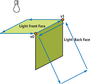
Figure 9-8 Winding Direction
Example 9-7. The renderShadowSides Method
void Object::renderShadowSides()
{
  index.resize(0);
  for (int e = edges.size() - 1; e > = 0; --e)
  {
if (backface[edge[e].face[0]] != backface[edge[e].face[1])
{
  // This is a silhouette edge
  int v0, v1;
if (backface[edge[e].face[0]))
  {
    // Wind the same way as face 0
    v0 = edge[e].vertex[0];
    v1 = edge[e].vertex[1];
  }
else
{
  // Wind the same way as face 1
  v1 = edge[e].vertex[0];
  v0 = edge[e].vertex[1];
}
// (The "directional" optimization changes this code.)
index.pushBack(v0);
index.pushBack(v1);
index.pushBack(v1 + n);
index.pushBack(v0 + n);
}
  }
  // (The "directional" optimization changes this to use
  // GL_TRIANGLES instead of GL_QUADS.)
  glDrawElements(GL_QUADS, index.size(), GL_UNSIGNED_INT, index.begin());
}
We've now walked through the entire shadow-rendering procedure. We've built a system that classifies pixels as shadowed or unshadowed in the stencil buffer and then adds illumination to only the unshadowed pixels. This system can handle many different kinds of light sources and complex shadow-caster geometry. It can also interoperate with other shadow algorithms such as projective shadows and shadow maps. The program can be altered to add illumination only to those areas that pass all the shadow tests.
By taking advantage of some common cases where the shadow volume algorithm is simplified, we can significantly speed up the process. The remainder of this chapter describes ways of speeding up shadow volume creation and rendering. In practice, the following methods can quadruple the speed of the base algorithm.
9.4 Debugging
To see if you are generating the shadow volumes correctly, temporarily enable color rendering and then draw shadow volumes with additive alpha blending. Turn on face culling and use one color for front faces and another for back faces. These shapes have other uses beyond debugging: you might want to render visible shadow volumes during gameplay for effects such as light rays passing through clouds or trees.
Remember that OpenGL requires the stencil test to be enabled, even if it is set to GL_ALWAYS_PASS, when using a stencil operation. Also, don't forget the stencil mask: glStencilMask(~0). If you forget either of these prerequisites, your write operations will be ignored.
Use assertions to check that every edge has exactly two adjacent faces. If you have cracks in a model, you'll get shadow streaks in the air like those we saw in Figure 9-3. Software modelers such as 3ds max have tools to fix cracks (called welding vertices) automatically—use them!
9.5 Geometry Optimizations
For clarity and simplicity, the base shadow-volume algorithm was described in the first half of the chapter in generic form, with directional lights, point lights, and spotlights treated the same. We used the mathematical trick L.xyz() - V * L.w in Listing 9-5 and a similar one in the vertex shader in Listing 9-3. These listings compute the light vector for both types of light with a single expression. We can improve performance by treating them separately in the vertex shader and throughout the process of generating shadow volumes. The shadow volume created by a directional light is simpler than that created by a point light, so this can turn into a big savings (at the expense of code complexity).
We can also improve geometry processing performance by using conservative bounding volumes to cull shadow geometry. This section describes these optimizations.
9.5.1 Directional Lights
For a directional light, the light vector is just L.xyz. Because the light vector is the same at all vertices, all vertices in the dark cap are at the same point, which is -L. This means there is no dark cap: the (parallel) sides of the shadow volume converge at infinity to a single point, and so the cap is unnecessary.
Because they converge to a point, the sides are triangles, not quads. The push statements in renderShadowSides (Listing 9-7) become:
index.pushBack(v0);
index.pushBack(v1);
index.pushBack(n);
These statements not only have fewer indices, but they are more friendly to the vertex cache. That's because the same vertex number n is transferred multiple times (we could transfer any one vertex with index greater than or equal to n, because they all transform to the same point). Alternatively, we could eliminate the vertex shader altogether and add one more vertex with index 2n that is set to the negative light vector before each shadow pass.
9.5.2 Point Lights and Spotlights
Point lights are typically attenuated by distance. After a certain distance, the light given off by a point light is negligible (when it drops below 1/255, we can't even see the result in an eight-bit frame buffer). Spotlights are attenuated by angle, and sometimes by distance. Outside the cone of the spotlight, they give no illumination.
If an object is outside the effective range of either kind of light source, it does not need to cast a shadow, because any object behind it is also outside the range. Detect this case by testing the bounding box of a shadow caster against the bounding sphere of a distance-attenuated light, or against the cone of an angularly attenuated light. When an object is outside the range, don't mark shadows for it. Likewise, no illumination pass is needed for objects outside the light's range.
9.5.3 Culling Shadow Volumes
Just as with regular geometry, the vertex-processing rate may be improved for shadow volumes by culling shadow geometry outside the view frustum. Note that the caster may be outside the view frustum and still cast a shadow on visible objects, so culling the caster and the shadow geometry are completely independent.
Cull the sides and cap separately. For each, approximate the shadow geometry with a geometric primitive and cull that primitive against the view frustum. The light cap can use the same bounds as the caster geometry, because the cap is inside the caster. The dark cap uses the same geometry, but sent to infinity away from the light source.
For example, say a bounding box is available for the caster. Transform each vertex, v, of the bounding box to infinity using the equation v' = MV * (v * L w - L xyz where L is the object-space light vector and MV is the modelview matrix. Then test the transformed bounding box against the view frustum. If the box is culled, the dark cap can also be culled. The shadow volume sides are most easily bounded by a cylinder for directional lights and by a truncated cone for point lights.
Although any culling is helpful, culling the caps particularly speeds up vertex processing because caps have many more vertices than sides. For point lights, the dark cap is potentially huge; culling it can also save a lot of fill rate. This is the effect we see in cartoons when a kitten casts a lion's shadow by standing in front of a flashlight. This magnifying effect was illustrated in Figure 9-7, where the dark cap for the model is several times larger than the model itself.
9.5.4 Uncapped Performance
Even when the caps would otherwise be unculled, we can use another technique to remove the caps for a special case in which the viewport is unshadowed.
In the mathematical formulation, we used rays from a point to infinity away from the viewer. In the implementation, these rays were simulated by rendering polygons to the stencil buffer. We moved the far clipping plane to infinity and sent rays away from the viewer so that we wouldn't miss any intersections between the point and infinity because of clipping.
It's possible to count in the other direction. To count away from the viewer, increment or decrement the stencil buffer when the depth test fails. To count toward the viewer, increment or decrement when the depth test passes. When the viewport is not in a shadow volume, the number of intersections along a line segment from an unshadowed point to the image plane is zero. This is because the line had to pass through exactly the same number of entering and exiting intersections to get from an unshadowed point to an unshadowed viewport. If the point is shadowed, the number of intersections will be nonzero. Of course, we can count in this direction only if the viewport is not in a shadow itself; otherwise, the count will be off by the number of shadow volumes enclosing each viewport pixel. Figure 9-7 showed a case where this optimization can be used because the shadows, which stretch back into the scene, do not enclose the viewport. Figure 9-2 showed an example where it cannot be used, because the viewport is in the shadow cast by the pumpkin—in fact, everything in the scene is in shadow, except the triangles of ground plane, where light shines out of the eyes.
The advantage of counting toward the viewer is that we don't need to render the light and dark caps. The light cap will always fail the depth test, because it is inside the shadow caster, so there is no reason to render it. Because we're counting from visible points to the viewer, there is no way for the dark cap (which is at infinity) to create intersections, and so we don't need to render it, because it can't change the result.
This optimization requires two changes to the code:
- We need to test whether the viewport is (conservatively) in a shadow volume. This test is performed separately for each shadow caster; we can choose our counting direction independently for each caster and still get a correct result.
- If the viewport is not in a shadow volume, we need to reverse the increment/decrement sense of the stencil operations (for that caster only).
Figure 9-9 shows the occlusion pyramid of the viewport. The tip is at the light source (which is at infinity if it is a directional light), and the base is the viewport. If the bounding box of the shadow caster intersects this pyramid, the viewport may be shadowed and the optimization cannot be used. In that case, we must render with the normal depth-fail operations and draw both caps, if visible. If the bounding box does not intersect the pyramid, we can change the stencil operations.
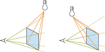
Figure 9-9 The Occlusion Pyramid
The occlusion pyramid can be on either side of the viewport. If the shadow caster intersects the green pyramid, the "uncapped" optimization cannot be used.
For counting toward the viewer, set the stencil operations as follows:
// Increment on front faces, decrement
// on back faces (a.k.a. z-pass rendering)
glActiveStencilFaceEXT(GL_FRONT);
glStencilOp(GL_KEEP, GL_KEEP, GL_INCR_WRAP_EXT);
glActiveStencilFaceEXT(GL_BACK);
glStencilOp(GL_KEEP, GL_KEEP, GL_DECR_WRAP_EXT);
Because this is "uncapped" rendering, omit the code to render shadow volume caps entirely from this case.
9.6 Fill-Rate Optimizations
Fill rate is the Achilles heel of shadow volumes. Shadow volumes cover many pixels and have a lot of overdraw. This is particularly troublesome for point lights, which create shadows that get bigger the farther they are from the caster. Fortunately, point lights also have great optimization potential, because their attenuation creates a range beyond which illumination is practically zero. We've already discussed not marking shadows for casters outside this range and not rendering illumination on objects outside the range. Now we'll look at three ways to reduce the fill rate required for casters inside the range: finite volumes, XY clipping, and z-bounds.
9.6.1 Finite Volumes
The range of a point light forms a sphere. Objects outside this sphere don't receive illumination, so there is no need to cast shadows beyond the sphere. Instead of extruding shadow volumes to infinity, we can extend them by the radius of the sphere and save the fill rate of rendering infinite polygons. This is a straightforward change to the vertex shader that can recoup significant fill rate. Because the dark cap is more likely to be on-screen under this method, it may increase the geometry processing because the dark cap is less likely to be culled.
An alternative is to still create polygons that stretch to infinity, but clip them to the light radius in 2D, as described in the next optimization.
9.6.2 XY Clipping
The range sphere projects to an ellipse on screen. Only pixels within that ellipse can be illuminated. We don't need to render shadow polygons or illumination outside of this ellipse. However, hardware supports a rectangular clipping region, not an elliptical one. We could compute the bounding box of the projected ellipse, but it is more convenient to use the 2D bounding box of the projected 3D bounding box surrounding the light range. Although the fixed-function pipeline supports only radial attenuation, artists can achieve more controlled effects by specifying an arbitrary attenuation function over the cubic volume about a light, as done in Doom 3. Attenuation can fall off arbitrarily within a box, so we just use that box as the light range. Clip the light's box to the view frustum. If it is not entirely clipped, project all vertices of the remaining polyhedron onto the viewport and bound them. That final 2D bound is used as the rectangular clipping region. Set the clipping region with the glScissor command:
glScissor(left, top, width, height);
glEnable(GL_SCISSOR_TEST);
Figure 9-10 shows a Quake 3 character standing outside a building. This is the scene from Figure 9-7, but now the camera has moved backward. The single point light creates shadow volumes from the character and the building (shown in yellow), which would fill the screen were they not clipped to the effective bounds of the light. The scissor region is shown in the right half of the figure as a white box. The left half of the figure shows the visible scene, where the effect of clipping is not apparent because the light does not illuminate the distant parts of the building. For this scene, rendering only the shadow volume pixels within the scissor region cuts the fill-rate cost in half.
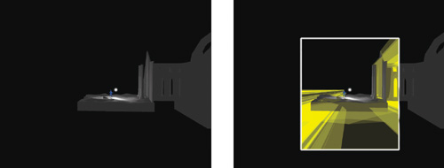
Figure 9-10 Clipping in
9.6.3 Z-Bounds
If the point at a given pixel is outside of the light range—because it is either closer to the viewer or farther from the viewer than the range bounds—that point cannot be illuminated, so we don't need to make a shadow-marking or illumination pass over that pixel. Restricting those passes to a specific depth range means that we pay fill rate for only those pixels actually affected by the light, which is potentially fewer pixels than those within the 2D bounds of the light.
The glDepthBoundsEXT function lets us set this behavior:
glEnable(GL_DEPTH_BOUNDS_TEST_EXT);
glDepthBoundsEXT(zMin, zMax);
This setting prevents rendering a pixel where the depth buffer already has a value outside the range [zMin, zMax]—that is, where the point visible at that pixel (rendered in the ambient pass) is outside the range. This is not the same as a clipping plane, which prevents rendering new pixels from polygons past a bound.
Figure 9-11 shows a viewer looking at an object illuminated from a point light. The caster's shadow projects downward toward the rugged ground slope. The bold green portion of the ground can't possibly be shadowed by the caster. The depth-bounds test saves the fill rate of rendering the orange parts of the shadow volume because the visible pixels behind them (the bold green ones) are outside the bounds. Notice that the shadow volume itself is inside the bounds, but this is irrelevant—the depth bound applies to the pixel rendered in the ambient pass, not to the shadow geometry.
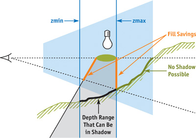
Figure 9-11 Depth Bounds
Note that the depth bounds are more restrictive than just the light range. It is the depth range defined by the intersection of the view frustum, the light range, and the shadow volume bounds. The arguments to the OpenGL function are post-projective camera-space values. If the geometry of the intersection is defined by a polyhedron whose vertices are stored in an array std::vector<Vector4> boundVert, the arguments are computed as:
float zMin = 1.0f;
float zMax = 0.0f;
for (int v = boundVertex.size() - 1; v > = 0; --v)
{
  float z = 1.0f / (projectionMatrix * boundVert[v]).w;
  zMin = min(zMin, z);
  zMax = max(zMax, z);
}
9.7 Future Shadows
The current, highly optimized shadow volume method is the result of contributions from industry and academia over the past several decades. The basic method was introduced by Frank Crow at SIGGRAPH 1977 and has matured into the method described in this chapter. The history of shadow volumes and the individual contributions of several researchers and developers are summarized in technical reports available on the NVIDIA Developer Web site (Everitt and Kilgard 2002, McGuire et al. 2003). McGuire et al. 2003 gives a formal description and analysis of the method presented in this chapter.
Improving the performance of shadow volume generation through new optimizations continues to be an active research area. Silhouette determination has always been performed on the CPU, which is a major limitation. It precludes the use of matrix skinning or other deformations in the vertex shader and otherwise serializes rendering on CPU operations.
Several solutions have been proposed for performing silhouette determination directly on programmable graphics hardware. Michael McCool (2001) proposed a method for computing the caster silhouettes from a shadow map. Brabec and Seidel (2003) push geometry encoded as colors through the pixel processor, where they compute silhouettes. They then read back the frame buffer and use it as a vertex buffer for shadow rendering. John Hughes and I recently described how to find silhouettes and extrude them into shadow volume sides entirely in a vertex shader using a specially precomputed mesh (McGuire and Hughes 2003).
Getting good-looking, high-performance soft shadows from area light sources with shadow volumes is another open research topic. Ulf Assarsson and Tomas Akenine-Möller have worked on this problem for some time. Their most recent paper, with Michael Dougherty and Michael Mounier (Assarsson et al. 2003), describes how to construct explicit geometry for the interior and exterior edges of the penumbra (the soft-shadow region) and makes heavy use of programmable hardware.
Several people have proposed joining the individual silhouette edges into connected strips so that quad strips (for point lights) and triangle fans (for directional lights) can be used to render the shadow volume sides. Alex Vlachos and Drew Card (2002) have been working on another simplification idea: culling and clipping nested shadow volumes, because they won't affect the final result.
All of these methods are experimental and have yet to be refined and proven in an actual game engine. If you are interested in moving beyond the capabilities of the current shadow volume method, these are good starting points. Hopefully, future research and graphics hardware will improve and accelerate these methods.
9.8 References
Assarsson, U., M. Dougherty, M. Mounier, and T. Akenine-Möller. 2003. "An Optimized Soft Shadow Volume Algorithm with Real-Time Performance." In Proceedings of the SIGGRAPH/Eurographics Workshop on Graphics Hardware 2003.
Brabec, S., and H. Seidel. 2003. "Shadow Volumes on Programmable Graphics Hardware." Eurographics 2003 (Computer Graphics Forum).
Everitt, Cass, and Mark Kilgard. 2002. "Practical and Robust Stenciled Shadow Volumes for Hardware-Accelerated Rendering." NVIDIA Corporation. Available online at http://developer.nvidia.com/object/robust_shadow_volumes.html
McCool, Michael. 2001. "Shadow Volume Reconstruction from Depth Maps." ACM Transactions on Graphics, January 2001, pp. 1–25.
McGuire, Morgan, and John F. Hughes. 2003. "NPR on Programmable Hardware." To appear in Proceedings of NPAR 2004, June 7–9, Annecy, France.
McGuire, Morgan, John F. Hughes, Kevin Egan, Mark Kilgard, and Cass Everitt. 2003. "Fast, Practical and Robust Shadows." Available online at http://developer.nvidia.com/object/fast_shadow_volumes.html . An early version appeared as Brown Univ. Tech. Report CS03-19.
Vlachos, Alex, and Drew Card. 2002. "Computing Optimized Shadow Volumes." In Game Programming Gems 3, edited by Dante Treglia. Charles River Media.
Tekkaman Blade robot model by Michael Mellor (mellor@iaccess.com.au); Tick model by Carl Schell (carl@cschell.com). Both available for download at http://www.polycount.com. Cathedral model by Sam Howell (sam@themightyradish.com), courtesy Sam Howell and Morgan McGuire. "The Tick" character is a trademark of New England Comics. Quake 2, Quake 3, and Doom 3 are trademarks of id Software.
Copyright
Many of the designations used by manufacturers and sellers to distinguish their products are claimed as trademarks. Where those designations appear in this book, and Addison-Wesley was aware of a trademark claim, the designations have been printed with initial capital letters or in all capitals.
The authors and publisher have taken care in the preparation of this book, but make no expressed or implied warranty of any kind and assume no responsibility for errors or omissions. No liability is assumed for incidental or consequential damages in connection with or arising out of the use of the information or programs contained herein.
The publisher offers discounts on this book when ordered in quantity for bulk purchases and special sales. For more information, please contact:
U.S. Corporate and Government Sales
(800) 382-3419
corpsales@pearsontechgroup.com
For sales outside of the U.S., please contact:
International Sales
international@pearsoned.com
Visit Addison-Wesley on the Web: www.awprofessional.com
Library of Congress Control Number: 2004100582
GeForce™ and NVIDIA Quadro® are trademarks or registered trademarks of NVIDIA Corporation.
RenderMan® is a registered trademark of Pixar Animation Studios.
"Shadow Map Antialiasing" © 2003 NVIDIA Corporation and Pixar Animation Studios.
"Cinematic Lighting" © 2003 Pixar Animation Studios.
Dawn images © 2002 NVIDIA Corporation. Vulcan images © 2003 NVIDIA Corporation.
Copyright © 2004 by NVIDIA Corporation.
All rights reserved. No part of this publication may be reproduced, stored in a retrieval system, or transmitted, in any form, or by any means, electronic, mechanical, photocopying, recording, or otherwise, without the prior consent of the publisher. Printed in the United States of America. Published simultaneously in Canada.
For information on obtaining permission for use of material from this work, please submit a written request to:
Pearson Education, Inc.
Rights and Contracts Department
One Lake Street
Upper Saddle River, NJ 07458
Text printed on recycled and acid-free paper.
5 6 7 8 9 10 QWT 09 08 07
5th Printing September 2007
- Contributors
- Copyright
- Foreword
- Part I: Natural Effects
-
- Chapter 1. Effective Water Simulation from Physical Models
- Chapter 2. Rendering Water Caustics
- Chapter 3. Skin in the "Dawn" Demo
- Chapter 4. Animation in the "Dawn" Demo
- Chapter 5. Implementing Improved Perlin Noise
- Chapter 6. Fire in the "Vulcan" Demo
- Chapter 7. Rendering Countless Blades of Waving Grass
- Chapter 8. Simulating Diffraction
- Part II: Lighting and Shadows
-
- Chapter 9. Efficient Shadow Volume Rendering
- Chapter 10. Cinematic Lighting
- Chapter 11. Shadow Map Antialiasing
- Chapter 12. Omnidirectional Shadow Mapping
- Chapter 13. Generating Soft Shadows Using Occlusion Interval Maps
- Chapter 14. Perspective Shadow Maps: Care and Feeding
- Chapter 15. Managing Visibility for Per-Pixel Lighting
- Part III: Materials
- Part IV: Image Processing
- Part V: Performance and Practicalities
-
- Chapter 28. Graphics Pipeline Performance
- Chapter 29. Efficient Occlusion Culling
- Chapter 30. The Design of FX Composer
- Chapter 31. Using FX Composer
- Chapter 32. An Introduction to Shader Interfaces
- Chapter 33. Converting Production RenderMan Shaders to Real-Time
- Chapter 34. Integrating Hardware Shading into Cinema 4D
- Chapter 35. Leveraging High-Quality Software Rendering Effects in Real-Time Applications
- Chapter 36. Integrating Shaders into Applications
- Part VI: Beyond Triangles
- Preface