
GPU Gems
GPU Gems is now available, right here, online. You can purchase a beautifully printed version of this book, and others in the series, at a 30% discount courtesy of InformIT and Addison-Wesley.
The CD content, including demos and content, is available on the web and for download.
Chapter 33. Converting Production RenderMan Shaders to Real-Time
Stephen Marshall
Sony Pictures Imageworks
33.1 Introduction
Since the late 1980s, visual effects houses have used shading languages to generate convincing images for the motion picture industry. Although these shading languages are extremely powerful, the complexity they need in order to produce innovative images often leads to long rendering times. Additionally, with the demand for bigger and better effects, the complexity of these shaders increases.
If the rendering time takes hours per frame, it is critical to be able to visualize incremental changes in the least amount of time. Consequently, visual effects houses are considering real-time gaming techniques for optimized visualization. In particular, the recent advances of graphics hardware technology and the development of hardware shading languages have offered a recognizable mapping between real-time and production effects.
This chapter demonstrates that it is possible to convert a Pixar RenderMan surface shader into a hardware shader. The hardware shading language used is Cg. Using Cg does not limit the scope of the chapter, because the Cg compiler can generate many different forms of shader instructions, including OpenGL ARB_fragment program-compliant code. See NVIDIA 2002 for details. The concepts we present are applicable to other shading languages as well.
You can find each listing mentioned in this chapter on the book's CD or Web site, in the appropriate subdirectory. For example, Listing 33-1, which contains the fur shader for Stuart Little, is in the listing1 subdirectory for Chapter 33.
33.1.1 Conversion by Example
The RenderMan fur shader from the movie Stuart Little is used throughout this chapter as an example of converting a RenderMan shader to a Cg program (see Berney and Redd 2000 for a description of the fur shader). The topics covered are the following:
- Frequency-independent issues, particularly handling multiple light sources
- A comparison of vertex and fragment programs, with close attention paid to hardware-specific optimizations (which are necessary for good performance)
- An analysis of the results, which covers the differences between the original Cg shaders and their optimizations, as well as the differences between the Cg and RenderMan results
33.2 Lights
As of this writing, lights and the way they are handled are arguably the largest deviation from the RenderMan specification when writing Cg code. That's because these RenderMan constructs have no equivalent mapping. This section covers light sources and light source shaders.
33.2.1 Light Sources
In RenderMan, light sources are iterated over by the illuminance statement. The illuminance statement lets the surface shader gather samples over all light sources in a scene, at the point being shaded. Extra information, beyond the light color and the light direction vector, can be exchanged between the surface and the light through message passing. More information on this topic can be found in Upstill 1990.
The single illuminance statement in the RenderMan fur shader code is:
// RenderMan illuminance statement illuminance (P, norm_hair,
// radians(illum_width))
This statement indicates that the following code will be executed for all lights in the scene that satisfy the illuminance condition. Unfortunately, there is no equivalent statement in Cg. The number of lights in the scene must be known before a shader can be written. Also, each light might have a grouping of similar parameters, but with different values. For example, if all lights in the scene are simple directionals, each light in the parameter list needs at least a light direction vector. If there are ten lights in the scene, the parameter list might look like this:
// Example Cg shader parameter list Output cgProgram(Input In,
uniform float3 lightDir[10],
    ..., // Other program parameters
It's possible to loop over the ten lights, but the process is inflexible. The Cg program must be modified if more than ten light sources are needed.
An alternate approach is to execute the program in a multipass fashion. If all the lights have similar parameters, only the current light's parameters are bound to the current render state. The result of the pass is then added into the frame buffer. So it is not necessary to specify the number of lights in the scene for the Cg program. Now it is left to the application to manage this information. This has the nice side effect of simplifying the parameter list of the Cg program to:
// Example Cg shader parameter list with multipass in mind Output
cgProgram(Input In,
uniform float3 lightDir,
// Other program parameters
Note that although this resolves the need for rewriting the Cg program, there is a necessary performance hit from running multiple passes of our program. As the number of lights in the scene increases, expect a significant decrease in application performance if the Cg program is complex.
33.2.2 Light Source Shaders
Likewise, there is no equivalent Cg statement for the concept of the RenderMan light source shader. A similar assumption can be made for light source shaders as was made for light sources—that all lights in the scene share the same shader.
This may seem like a serious limitation for production use. However, it's common to have a main light source shader that encapsulates all usable light parameters. A single Cg function can be written to implement the common complex lighting equation. More information on implementation of this topic can be found in Barzel 1997 and Gritz 1998.
33.2.3 Additional Lighting Parameters
A complex light source shader can potentially add many parameters to the Cg program. The shader preprocessor can manage this complexity—as well as help with readability—by defining multiple light shader parameter lists. The following two lists are defined and used to simplify the program's parameter list:
// uber_light parameter list
#define DEFINE_UBER_LIGHT_PARAMS
uniform float3 lightColor, uniform float lightIntensity,
    uniform float lightConeInner, uniform float lightConeOuter,
    uniform float lightConeRoundness,
    ...
// uber_light parameters
#define UBER_LIGHT_PARAMS
    lightColor,
    lightIntensity, lightConeInner, lightConeOuter, lightConeRoundness, ...
The Cg shader entry point can then be simplified to:
// Example Cg shader parameter list with multipass in mind Output
cgProgram(Input In,
DEFINE_UBER_LIGHT_PARAMS,
// ...,
// Other program parameters
The call to the light source implementation in the cgProgram block might look like this:
// Example Cg shader parameter list with multipass in mind
float3 lightColor = uber_light(UBER_LIGHT_PARAMS,
. . . , // Other parameters
Finally, the message-passing facilities in RenderMan must be replaced. This is trivial because the shader is aware of the parameter values for the current light source. These parameter values are encapsulated in the previous parameter list definitions of the Cg program.
33.3 The Vertex Program vs. the Fragment Program
Writing Cg programs (instead of RenderMan shaders) involves different concepts of computation frequency. The execution rate of a shader in RenderMan is governed by the ShadingRate parameter (Apodaca and Gritz 2000). This parameter is a floating-point value that specifies the area (in pixels) that a shading sample can represent.
In contrast, the rate that shading occurs in the GPU is defined by the type of program in use. For example, all operations for a vertex program are performed on vertex data passed to the GPU from the API (OpenGL, Microsoft DirectX, and so on). However, all operations of a fragment program are executed on primitives that directly relate to a pixel in the final image.
In hardware, vertex and fragment programs do not necessarily have the same capabilities. In many cases, these programs must work together to supply the same functionality that a single RenderMan surface shader provides. A vertex program overrides the transformation and lighting portion of the graphics pipeline. Consequently, at least a homogeneous clip-space position for the input vertex must be provided. Thus, the transformation portion of the pipeline must be produced manually by passing the modelview projection matrix to the program, transforming the incoming vertex, and assigning the new vertex position to the output vertex-position register. This differs from RenderMan because in RenderMan, it's not necessary to worry about the output of the shader, except for the final color.
In contrast, a fragment program overrides the multitexturing portion of the graphics pipeline, so any texture operation must be performed manually. The result of executing a fragment program is the color for the fragment and possibly a new depth. This new color must be bound to the output color register.
Cg is a hardware-independent language. It is only through hardware profiles that the compiler is made aware of the platform for which it is building. More details on hardware limitations can be found in Appendix B of NVIDIA 2002. The reader is encouraged to read and understand these details before writing hardware shaders.
33.4 Using Vertex and Fragment Programs
As mentioned earlier, it is often necessary to write a vertex and a fragment program to achieve the same functionality of a RenderMan shader. For our fur example, a vertex program prepares the rasterization process, and the shading calculations are implemented in the fragment program. Listing 33-2 shows an initial implementation of a vertex program set up to seed the rasterizer for the fragment program.
The vertex program processes two types of data. The first are attribute values generated in the vertex program. For example, the light direction (L) and the eye direction (V), which are needed by the fragment shader, depend on the position of the input vertex. Because of this dependency, these values are computed in the vertex program at runtime.
Additional per-vertex data can be passed through the vertex shader to the fragment shader as data streams. These attributes are passed and assigned directly to the outputs of the vertex program without further processing. For our fur example, these attributes are the normalized hair tangents (T), a hair parameter value (v), and a surface normal (nSN). This is similar to assigning extra primitive variables to geometry in RenderMan. The difference between RenderMan and the vertex program is that values can be generated through an interpolation scheme in RenderMan (for example, by interpolating data specified at the control points of a NURBS surface). The vertex program merely receives uninterpolated data passed in from the application.
The interpolation of data for the GPU occurs before the fragment program, in the rasterization phase. The user has no control over how the intermediate fragment values are computed. Values passed through the standard graphics pipeline are linearly interpolated across a scanline. This indicates that the sample rate of the input geometry will affect the final quality of the image.
The final component is the fragment program itself, where most of the shading calculations are performed. Listing 33-3 shows the Cg fragment program, which is almost identical to the original RenderMan shader. The initial conversion is very tractable because Cg provides many of the same standard library functions as RenderMan. The only important differences are the interactions with the vertex program, the different names for the program types, and the introduction of the saturate, dot, and cross functions. The saturate function is a minimal-cost function that should be used when clamping a value between 0 and 1. The dot and cross functions are used to replace the . and ^ operators in the RenderMan shading language.
33.5 Optimization Techniques on the Fragment Program
The implementation of the current fragment program may seem adequate; however, it will run slowly. This may seem disappointing at first, but remember that the GPU is not a typical processor. Although converting the fur shader was trivial, the architecture of the hardware was not taken into account. The GPU is composed of two processors: the vertex processor and the fragment processor. It is preferable to do as much computation as possible in the vertex processor, which is only executed on each vertex, because there will generally be far fewer vertices in the model than fragments in the final image. The vertex processing may be complemented by some amount of high-quality processing in the fragment program, because the fragment programs execute on all generated fragments—visible and not visible. Also, computations that do not change over the course of interaction should be moved into the application level; it's wasteful to recompute them each time the vertex or fragment program executes.
It is also important to consider the vectorized nature of the GPU. In general, the GPU can perform a set of four arithmetic instructions in the same time it can perform a set of one, two, or three. The shader source code should be organized to help the compiler recognize and optimize for these cases. Finally, because texture-map lookups on the GPU are extremely efficient, 1D, 2D, and 3D textures can be used as lookup tables for complex functions of one, two, or three variables, respectively.
The goal is to reduce the size of the fragment program. In general, the shorter the program, the faster the execution. If the fp30 profile is used, the compiled size of our original fragment program is 104 instructions. A reduction in size and a gain in efficiency can be achieved if the user has a more in-depth understanding of the hardware.
33.5.1 Moving Code to the Application Level
In the first part of the fragment program, it is clear the code does not change if the view or light changes:
// Fragment Program lines
float3 S = cross(IN.nSN, IN.T);
float3 N_hair = cross(IN.T, S);
float l = saturate(dot(IN.nSN, IN.T));
float3 hairNorm = normalize((l * IN.nSN) + ((1.0f - l) * N_hair));
This part can therefore be moved into the application level, where the new attribute, hairNorm, will be passed to the vertex program.
33.5.2 Moving Code to the Vertex Program
The next set of dot-product calculations cannot be moved into the application level because the L and V vectors depend on the light and eye positions, respectively:
float T_Dot_nL = saturate(dot(IN.T, IN.L));
float T_Dot_nV = saturate(dot(IN.T, IN.V));
This set of calculations may, however, be moved into the vertex program because the vectors are generally changing slowly along the fragments generated from a single segment of the curve. In general, the higher the sampling rate along the curve, the less error will be introduced due to this interpolation.
We can estimate the amount of potential error from this interpolation in a rigorous manner. Because the dot product is equal to the cosine of the angle between two normalized vectors, using the analysis of Crenshaw 2000, the error function for a single-valued cosine function is:
Assuming that the maximum error occurs at the point of highest curvature, x 1 and x 2 are placed about cos(0). Then:

Therefore:
Using the trigonometric identity:

where for this example a = 0 and b =x/2, Equation 1 becomes:
Assuming that x is small enough, the cosine term of Equation 5 can be approximated by the first two terms of an infinite-series expansion of the cosine function, giving:

As expected, Equation 6 shows that the largest errors occur where the sample rate is low. In particular, the tangent values need to be almost the same value from sample to sample. This means that the application must ensure that the hair is sampled higher in areas of higher curvature. If this assumption can be made, then the dot products, shown below, can be moved into the vertex program.
float2 dots = float2(saturate(dot(IN.T, IN.L)), saturate(dot(IN.T, IN.V)));33.5.3 Optimizing Through Texture Lookups
The Kajiya-Kay hair-shading model includes terms based on a complex function of two variables, T_Dot_nL and T_Dot_e.
float Alpha = acos(T_Dot_nL);
float Beta = acos(T_Dot_e);
float Kajiya = T_Dot_nL * T_Dot_e + sin(Alpha) * sin(Beta);
A more detailed derivation can be found in Kajiya and Kay 1989.
This set seems an ideal candidate for a texture lookup. A floating-point texture can be generated for this application. The texture function can then be sampled between 0 and 1 in both independent variables.
An analysis similar to the one in the previous section can be used to determine a sample rate and appropriate texture size for our function lookup; however, this is overly complicated. Instead, a separate program can be written that uses a simple fragment program to compute the difference between a texture lookup of the function and a full computation of the Kajiya-Kay terms. This difference can be displayed as a color for the final fragment. An appropriate texture size that minimizes error can be chosen by simple visual comparison, as shown in Figure 33-1.
Figure 33-1 Difference Image Between Texture Lookup and Full Computation
The Kajiya-Kay terms of the texture can now be found through this lookup:
float2 Kajiya = texRECT(kajiyaTexture, IN.dots);Note that the dot products computed in the vertex program in Section 33.5.2 are used as the texture lookup parameters. Also, note that the texRECT() function is used for texture lookup. As a result, the texture lookup must be done in an unnormalized texture space. This is accomplished by multiplying the texture-lookup parameters (the dot products in the vertex program) by the size of the Kajiya-Kay texture.
33.5.4 Optimizing for Vectorization
The following power functions compute the specular component of the shading term:
float3 Cspec = (spec.x * lightColor * pow(Kajiya, iroughness.x)) +
               (spec.y * lightColor * pow(Kajiya, iroughness.y));
This function can be reordered to take advantage of the vector form of multiplication. In particular, the result of the power functions can be multiplied with the spec components in parallel:
float2 powVal = spec * pow(Kajiya, iroughness);
float3 Cspec = lightColor * powVal.x + lightColor * powVal.y;
33.5.5 Final Optimizations
The diffuse component calculation of the shading term is performed in the function fnc_diffuselgt, defined at the top of Listing 33-3. This function also uses a dot product between the light direction and the hair normal. From the dot-product analysis in Section 33.5.2, we know that this function can be moved into the vertex program. The resulting varying attribute passed to the fragment program is called dComp.
The Kd multiplication and the final_c computation (minus the darkening term) can be moved to the vertex program to increase performance. Kd must be multiplied by the diffuse component that was moved earlier into the vertex program. The intermediate hair-color value is stored in the varying attribute hairCol. The vertex program code now looks like this:
OUT.hairCol = ((1.0 - IN.v) * rootColor) + (IN.v * tipColor);
OUT.dComp = saturate(dot(lDir, IN.hairNorm)) * Kd;
Finally, looking at the complete fragment color:
OUT.col.xyz = saturate((Kd * Cdiff + staticAmbient) * final_c +
                       (In.v * Kspec * Cspec * specularColor));
The IN.v * Kspec calculation can be moved into the vertex program, and the specular value can be stored in the varying attribute specColor to produce:
OUT.col.xyz = saturate((Cdiff + staticAmbient) * final_c +
                       (In.specColor * Cspec * specularColor));
Note that no conditional statements were used to eliminate unnecessary computations. Unfortunately, current GPUs do not support conditional code natively in the fragment program. Therefore, both the if and the else clauses of a conditional are computed, regardless of the result of the conditional. There is no performance benefit (and there might even be a slowdown from conditionals), so the computation should be calculated using the more complex version.
33.6 Results and Conclusions
This application was run on an Intel Pentium 4 with a 2.8 GHz Xeon processor and tested on Linux with an NVIDIA Quadro FX 2000 and an NVIDIA Quadro 4 980. The Cg version 1.1.0003 compiler was used to generate 27,488 b-spline curves with ten uniformly sampled points.
Although the conversion from the RenderMan shader to a fragment program was straightforward, the initial performance was disappointing. However, through the various optimization techniques discussed in this chapter, the fragment program size was reduced from 104 instructions to 42. This significantly increased the performance. Some concessions were made on the quality of the image because of the optimization. However, these differences turned out to be unnoticeable in practice.
Figures 33-2 and 33-3 show the original and optimized versions of the fragment program, respectively, and Figure 33-4 shows the difference between the two images produced by the two versions. Notice that the difference is negligible.
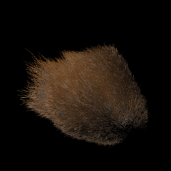
Figure 33-2 The Result of the Original Fragment Program
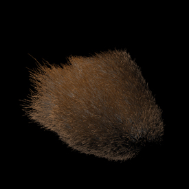
Figure 33-3 The Result of the Optimized Fragment Program
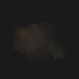
Figure 33-4 The Difference Between the Original and Optimized Images
Also of interest is the difference between the renderings produced by the fragment program and those produced by RenderMan. Using the same curve geometry, Figure 33-5 was rendered in 20 seconds with Pixar's PRMan. Although the image of the fragment program is slightly different from the RenderMan image, all the important highlights and color changes of the RenderMan image are produced in the correct locations of the fragment program image. It should be easy to see that the hardware version gives a reasonable approximation to the PRMan rendering in a fraction of the time.
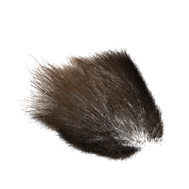
Figure 33-5 The Result of the PRMan Rendering
Production-quality characters often have millions of hairs. Even after culling, there are still hundreds of thousands of hairs to shade. The optimized fragment program becomes too slow for this type of character, so a complete fur shader was implemented in a vertex program, as shown in Listing 33-4. The results can be seen in Figure 33-6. Although this approach is less accurate than the fragment program, the performance gain is significant.
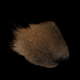
Figure 33-6 The Result of the Fur Shader Vertex Program
Note that if shader writers apply hand optimizations, the fragment program is very different from the original RenderMan surface shader. If it becomes necessary to modify the original RenderMan shader code, it might not be obvious to identify which section of code to modify in the hardware shader to make the equivalent change. This means that writers must be very knowledgeable in how RenderMan works, as well as how hardware shaders work.
No mention of RenderMan shadeops has been made in this chapter. A shadeop is a user-defined function written in C or C++ that adds functionality to the standard library of RenderMan. This takes the form of a shared library created by a user, which is dynamically loaded at runtime by the RenderMan renderer. The issue? Current GPUs do not allow this type of programmability. The texture-lookup method described in Section 33.5.3 can possibly replace this if the shadeop's parameter list can be simplified.
33.7 References
Apodaca, A., and L. Gritz. 2000. Advanced RenderMan: Creating CGI for Motion Pictures. Morgan Kaufmann.
Barzel, Ronen. 1997. "Lighting Controls for Computer Cinematography." Journal of Graphics Tools 2(1), pp. 1–20.
Berney, J., and J. Redd. 2000. "Stuart Little: A Tale of Fur, Costumes, Performance, and Integration: Breathing Real Life Into a Digital Character." SIGGRAPH 2000 Course 14.
Crenshaw, J. 2000. Math Toolkit for Real-Time Programming. CMP Books.
Gritz, L. 1998. "uberlight.sl". Available online at the RenderMan Repository: http://www.renderman.org/RMR/Shaders/BMRTShaders/uberlight.sl
Kajiya, J., and T. Kay. 1989. "Rendering Fur with Three Dimensional Textures." ACM Computer Graphics (SIGGRAPH 89) 23(3), pp. 271–280.
NVIDIA Corporation. 2002. Cg Toolkit User's Manual: A Developer's Guide to Programmable Graphics. Available online at http://developer.nvidia.com
Upstill, S. 1990. The RenderMan Companion: A Programmer's Guide to Realistic Computer Graphics. Addison-Wesley.
This work was supported by Sony Pictures Imageworks. I would also like to thank Murilo Coutinho, Maria Giannakouros, and Hiro Miyoshi for their many thoughtful comments and contributions.
Copyright
Many of the designations used by manufacturers and sellers to distinguish their products are claimed as trademarks. Where those designations appear in this book, and Addison-Wesley was aware of a trademark claim, the designations have been printed with initial capital letters or in all capitals.
The authors and publisher have taken care in the preparation of this book, but make no expressed or implied warranty of any kind and assume no responsibility for errors or omissions. No liability is assumed for incidental or consequential damages in connection with or arising out of the use of the information or programs contained herein.
The publisher offers discounts on this book when ordered in quantity for bulk purchases and special sales. For more information, please contact:
U.S. Corporate and Government Sales
(800) 382-3419
corpsales@pearsontechgroup.com
For sales outside of the U.S., please contact:
International Sales
international@pearsoned.com
Visit Addison-Wesley on the Web: www.awprofessional.com
Library of Congress Control Number: 2004100582
GeForce™ and NVIDIA Quadro® are trademarks or registered trademarks of NVIDIA Corporation.
RenderMan® is a registered trademark of Pixar Animation Studios.
"Shadow Map Antialiasing" © 2003 NVIDIA Corporation and Pixar Animation Studios.
"Cinematic Lighting" © 2003 Pixar Animation Studios.
Dawn images © 2002 NVIDIA Corporation. Vulcan images © 2003 NVIDIA Corporation.
Copyright © 2004 by NVIDIA Corporation.
All rights reserved. No part of this publication may be reproduced, stored in a retrieval system, or transmitted, in any form, or by any means, electronic, mechanical, photocopying, recording, or otherwise, without the prior consent of the publisher. Printed in the United States of America. Published simultaneously in Canada.
For information on obtaining permission for use of material from this work, please submit a written request to:
Pearson Education, Inc.
Rights and Contracts Department
One Lake Street
Upper Saddle River, NJ 07458
Text printed on recycled and acid-free paper.
5 6 7 8 9 10 QWT 09 08 07
5th Printing September 2007
- Contributors
- Copyright
- Foreword
- Part I: Natural Effects
-
- Chapter 1. Effective Water Simulation from Physical Models
- Chapter 2. Rendering Water Caustics
- Chapter 3. Skin in the "Dawn" Demo
- Chapter 4. Animation in the "Dawn" Demo
- Chapter 5. Implementing Improved Perlin Noise
- Chapter 6. Fire in the "Vulcan" Demo
- Chapter 7. Rendering Countless Blades of Waving Grass
- Chapter 8. Simulating Diffraction
- Part II: Lighting and Shadows
-
- Chapter 9. Efficient Shadow Volume Rendering
- Chapter 10. Cinematic Lighting
- Chapter 11. Shadow Map Antialiasing
- Chapter 12. Omnidirectional Shadow Mapping
- Chapter 13. Generating Soft Shadows Using Occlusion Interval Maps
- Chapter 14. Perspective Shadow Maps: Care and Feeding
- Chapter 15. Managing Visibility for Per-Pixel Lighting
- Part III: Materials
- Part IV: Image Processing
- Part V: Performance and Practicalities
-
- Chapter 28. Graphics Pipeline Performance
- Chapter 29. Efficient Occlusion Culling
- Chapter 30. The Design of FX Composer
- Chapter 31. Using FX Composer
- Chapter 32. An Introduction to Shader Interfaces
- Chapter 33. Converting Production RenderMan Shaders to Real-Time
- Chapter 34. Integrating Hardware Shading into Cinema 4D
- Chapter 35. Leveraging High-Quality Software Rendering Effects in Real-Time Applications
- Chapter 36. Integrating Shaders into Applications
- Part VI: Beyond Triangles
- Preface