
GPU Gems
GPU Gems is now available, right here, online. You can purchase a beautifully printed version of this book, and others in the series, at a 30% discount courtesy of InformIT and Addison-Wesley.
The CD content, including demos and content, is available on the web and for download.
Chapter 18. Spatial BRDFs
David McAllister
NVIDIA
The spatial bidirectional reflectance distribution function (SBRDF) represents the reflectance of a surface at each different point, for each incoming and each outgoing angle. This function represents the appearance of the surface in a very general, detailed way. This chapter discusses a compact SBRDF representation as well as rendering approaches for SBRDFs illuminated by discrete lights or by environment maps.
18.1 What Is an SBRDF?
An SBRDF is a combination of texture mapping and the bidirectional reflectance distribution function (BRDF). A texture map stores reflectance, or other attributes, that vary spatially over a 2D surface. A BRDF stores reflectance at a single point on a surface as it varies over all incoming and outgoing angles. See Figure 18-1.
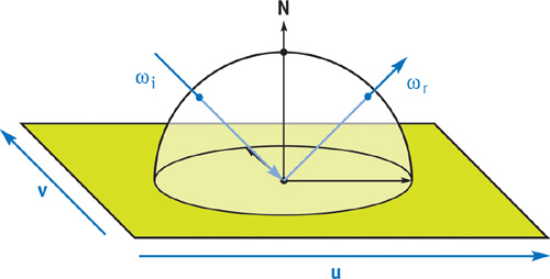
Figure 18-1 The SBRDF Domain
Real surfaces usually have significant variations, both spatially over the surface and angularly over all light and view directions. Thus, to represent most surfaces more realistically, we should combine BRDFs with texture mapping. This combination is the SBRDF. See McAllister 2002 for more details.
18.2 Details of the Representation
The most straightforward SBRDF representation is to store, at each texel of a texture map, all the parameters of that point's BRDF. Any BRDF representation could be used, but one that's compact and works well for hardware rendering is the Lafortune representation (Lafortune 1997). This representation consists of a sum of terms:
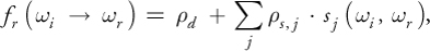
where d is the diffuse reflectance. The terms in the summation are specular lobes. Each lobe j has an albedo (reflectance scaling factor), s , j , and a lobe shape, sj . The incident and exitant directions are i and r . The lobe shape is defined as follows, similar to a standard Phong lobe:
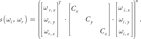
This equation can be thought of as a generalized dot product, in which the three terms are scaled arbitrarily:

See Figure 18-2.
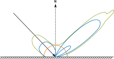
Figure 18-2 A BRDF (Green) Composed of Three Lobes (Blue) and a Diffuse Component (Orange)
The Lafortune representation is evaluated in local surface coordinates. The x axis and y axis
are in the direction of anisotropy (the scratch or thread direction), and the z axis is the normal.
Defining the matrix C as Cx = -1, Cy = -1,
Cz = 1 causes i to reflect about the normal, yielding a standard Phong
lobe. But the C coefficients may take on other values to shear the specular lobe in ways that represent
real surface-scattering behavior. The lobe's peak is in the direction C · i . For
isotropic BRDFs, Cx = Cy . For off-specular reflection,
 , pulling the lobe toward the tangent plane. For retroreflection, Cx > 0 and
Cy > 0. When Cx and Cy have opposite signs, a
lobe forward-scatters light arriving parallel to the principal direction of anisotropy, but it back-scatters
light arriving perpendicular to it, which models the behavior of threads and scratches.
, pulling the lobe toward the tangent plane. For retroreflection, Cx > 0 and
Cy > 0. When Cx and Cy have opposite signs, a
lobe forward-scatters light arriving parallel to the principal direction of anisotropy, but it back-scatters
light arriving perpendicular to it, which models the behavior of threads and scratches.
The Lafortune representation's flexibility to aim and scale each scattering lobe is key to successfully using only a few lobes to approximate the BRDFs. This property also enables the glossy environment mapping technique described in Section 18.4. The Lafortune representation is well suited to the shape BRDFs typically have. It's compact and is capable of representing interesting BRDF properties, such as the increasing reflectance of Fresnel reflection, off-specular peaks, and retroreflection.
The albedo values are RGB triples, but the Cx , Cy , Cz , and n values are shared between channels, totaling seven coefficients per specular lobe. One, two, or three specular terms are usually sufficient, depending on the nature of the surface and the quality-versus-speed tradeoff. With as few as ten coefficients (three diffuse plus seven specular), the SBRDF representation is only about three times larger than an RGB texture map, but it is dramatically more realistic.
The SBRDF data can be measured from real surfaces (McAllister 2002) or be painted by an artist using a custom-written paint program. The simplest painting approach is to use a palette of existing BRDFs and paint them into an SBRDF texture map. Palette entries can blend existing BRDFs, can be sampled from the SBRDF database (McAllister 2003), or can be defined using a dialog box to set the , Cx , Cy , Cz , and n values.
18.3 Rendering Using Discrete Lights
The SBRDF is loaded into texture memory the same way for either rendering approach. The diffuse color, d , is stored in one texture map (with its alpha channel available for alpha kill or other use). For each lobe, s is stored in one texture map (with its alpha channel unused or used for the direction of anisotropy), and Cx , Cy , Cz , and n are stored in a second map. When using eight-bit texture maps, a scale and bias must be applied, because the useful range of Cx and Cy values is about -1.1 to 1.1. Scaling by 96, then biasing by 128, works well. Depending on the available memory bandwidth and fragment shader performance, it may be more efficient to store SBRDF data in floating-point textures rather than eight-bit texture, thus avoiding scaling and improving accuracy.
The Cg shader for illuminating SBRDF surfaces by standard point or directional lights is simple, as shown in Listing 18-1. It is similar to a shader for the standard Phong model and hardware lights. One difference is that all BRDF parameters, rather than just the diffuse color, are sampled from texture maps. Another is that the evaluation of the dot product occurs in local surface coordinates, so that its components can be scaled by Cx , Cy , and Cz . This requires that light vectors come from the vertex program in local surface coordinates. See Figure 18-3 for sample results.
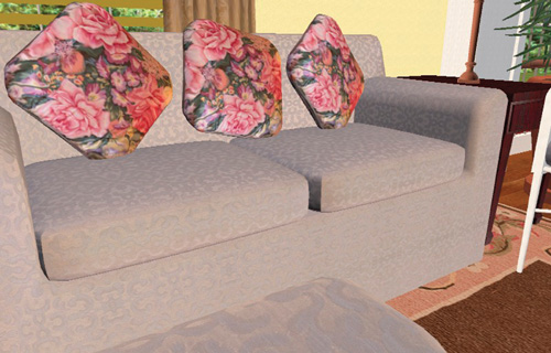
Figure 18-3 Rendering with Discrete Lights
Example 18-1. An SBRDF Fragment Shader for Discrete Lights
#define NUM_LOBES 3 #define NUM_LIGHTS 2
// Store Cx, Cy, Cz on range -1.3333 .. 1.3333.
#define SCL
(1.0 / (96.0 / 256.0)) #define BIAS(SCL / 2.0) #define EXSCL
    255.0 // Scale exponent to be on 0 .. 255.
    // Rasterize the view vector and all the light vectors.
    // Pass the light colors as uniform parameters.
    struct fromrast
{
  float2 TexUV : TEXCOORD0;
  // Surface texcoords
  float3 EyeVec : TEXCOORD1;
  // Vector to eye (local space)
  float3 LightVec[NUM_LIGHTS] : TEXCOORD2; // Lights (local space)
};
float4 main(fromrast I, uniform sampler2D tex_dif,
            // Diffuse
            uniform sampler2D tex_lshp[NUM_LOBES], // Lobe shape
            uniform sampler2D tex_lalb[NUM_LOBES], // Lobe albedo
            uniform float4 Expos, uniform float3 LightCol[NUM_LIGHTS])
    : COLOR
{
  // Load the BRDF parameters from the textures
  float4 lobe_shape[NUM_LOBES];
  float4 lobe_albedo[NUM_LOBES];
  for (float p = 0; p < NUM_LOBES; p++)
  {
    lobe_shape[p] =
        f4tex2D(tex_lshp[p], I.TexUV.xy) * float4(SCL, SCL, SCL, EXSCL) -
        float4(BIAS, BIAS, BIAS, 0.0);
    lobe_albedo[p] = f4tex2D(tex_lalb[p], I.TexUV.xy);
  }
  float4 dif_albedo = f4tex2D(tex_dif, I.TexUV.xy);
  // Vector to eye in local space.
  float3 toeye = normalize(I.EyeVec.xyz);
  // Accumulate exitant radiance off surface from each light
  float3 exrad = float3(0, 0, 0);
  for (int l = 0; l < NUM_LIGHTS; l++)
  {
    // Vector to light in local space.
    float3 tolight = normalize(I.LightVec[l].xyz);
    // Evaluate the SBRDF for this point and direction pair
    float3 refl = dif_albedo.xyz;
    for (float p = 0; p < NUM_LOBES; p++)
    {
      // Shear eye vector
      float3 Cwr_local = lobe_shape[p].xyz * toeye;
      float thedot = dot(Cwr_local, tolight);
      refl = refl + lit(thedot, thedot, lobe_shape[p].w).z * lobe_albedo[p].xyz;
    }
    // Irradiance for this light (incident radiance times NdotL).
    float NdotL = max(0, tolight.z);
    float3 irrad = LightCol[l] * NdotL;
    // Reflectance times irradiance is exitant radiance.
    exrad += refl * irrad;
  }
  float4 final_col = exrad.xyzz * Expos.xxxx; // Set HDR exposure.
  final_col.w = dif_albedo.w; // Put alpha from the map into pixel.
  return final_col;
}
18.3.1 Texture Sampling
Cx , Cy , Cz , and n are parameters of a nonlinear function, so applying bilinear or trilinear interpolation to these texture maps can cause sparkly artifacts. The simplest solution is to use point sampling for this map.
18.4 Rendering Using Environment Maps
Besides being illuminated with point or directional lights, SBRDFs can be illuminated with incident light from all directions by using environment maps. The key is to convolve the environment map with a portion of the BRDF before rendering. For most BRDF representations, this must be done separately for each different BRDF. But because one SBRDF might have a million different BRDFs, doing so would be impossible.
Instead, we simply convolve the environment map with Phong lobes that have a selection of different specular exponents—for example, n = 0, 1, 4, 16, 64, and 256. These maps can be stored in the various layers of a cube mipmap, with the n = 0 map at the coarsest mipmap level, and the n = 256 map at the finest mipmap level. The n value of the SBRDF texel then indicates the level of detail (LOD) value used to sample the appropriate mipmap level of the cube map.
An alternative representation of the set of convolved environment maps is a single 3D texture, with the s and t map dimensions mapping to a parabolic map (Heidrich and Seidel 1999) and the r dimension mapping to n.
18.4.1 The Math
The derivation begins by expressing the radiance of the pixel being shaded, L(r ), as separate diffuse and specular terms of the Lafortune BRDF:

with i representing integration over the incident hemisphere. The incident radiance, Li (i ), is stored in the environment map, which is indexed by the incident direction. The diffuse term can be easily encoded in an environment map indexed simply by N:

D(N) is independent of the BRDF, so it is precomputed once for all objects that are to reflect the environment map Li (i ). The specular terms also take advantage of precomputed maps. Just as N indexes the preconvolved diffuse map, a function of the view direction indexes a preconvolved specular environment map:
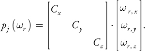
pj (r ) is the peak vector of the lobe-shaped sampling kernel—the incident direction of maximum influence on the exitant radiance toward r due to lobe j. The equation is then:

The environment map convolved with the specular lobe is:
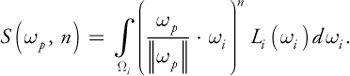
This equation creates the convolved environment maps, given the original environment map. As mentioned, this map is parameterized both on the incident kernel peak direction p and on the exponent n. The pseudocode in Listing 18-2 represents a brute-force method of computing an environment map convolved with a Phong lobe of exponent n.
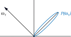
Figure 18-4 The Incident Lobe Peak for
Example 18-2. Pseudocode for Convolving an Environment Map with a Phong Lobe
float3 S(float3 Wp, float n)
{
  float3 Sum = 0.xyz;
  float WgtSum = 0;
  for (int si = 0; si < 6; si++)
  {
    for (int yi = 0; yi < YMAX; yi++)
    {
      for (int xi = 0; xi < XMAX; xi++)
      {
        float3 Wi = VecFromCubeMap(xi, yi, si);
        float dp = dot(Wp, Wi);
        if (dp < 0)
          continue;
        float lobe_shape = pow(dp, n);
        float3 FN = FaceNormal(si);
        // Scale irradiance by length of cube vector to
        // compensate for irregular cube map distribution.
        float3 Irrad = Li(Wi) * dp / length2(Wi);
        Sum += Irrad * lobe_shape;
        WgtSum += lobe_shape; // Compute volume of lobe
      }
    }
  }
  return Sum / WgtSum;
}
// Convolve the cube map Li with a Phong lobe of exponent n
CubeMap PrecomputeEnvMap(float n)
{
  CubeMap Smap;
  // Loop over all the pixels of the cube map
  for (int s = 0; s < 6; s++)
  {
    for (int y = 0; y < YMAX; y++)
    {
      for (int x = 0; x < XMAX; x++)
      {
        float3 Wp = VecFromCubeMap(x, y, s);
        Smap(x, y, s) = S(Wp, n);
      }
    }
  }
  return Smap;
}
The final formulation used in hardware rendering is:

The
 factor arises because S is computed with a normalized p , so the incident radiance
must still be scaled by the magnitude of the lobe. This equation is only an approximation, because the
irradiance falloff N · i must be computed inside the integral over
i . But this can't be stored in an environment map, because it would then be parameterized
by both p(r ) and N. The proposed formulation instead weights all
incident directions equally within the integral, but weights S(p , n) by
N · p(r ). This approximation has not presented a practical
problem.
factor arises because S is computed with a normalized p , so the incident radiance
must still be scaled by the magnitude of the lobe. This equation is only an approximation, because the
irradiance falloff N · i must be computed inside the integral over
i . But this can't be stored in an environment map, because it would then be parameterized
by both p(r ) and N. The proposed formulation instead weights all
incident directions equally within the integral, but weights S(p , n) by
N · p(r ). This approximation has not presented a practical
problem.
So with one environment map lookup and a few multiplies per lobe, we can render any number of independent BRDFs illuminated by the same set of arbitrary environment maps.
18.4.2 The Shader Code
Listing 18-3 shows the sample code for rendering with preconvolved environment maps. It calls the function f3texCUBE_RGBE_Conv( env_tex, dir, n ), which samples the preconvolved environment map at the given direction with an LOD computed based on n. See Figure 18-5 for the result.
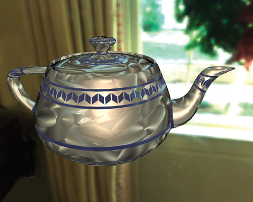
Figure 18-5 Rendering with an Environment Map
To compactly represent incident radiance values greater than 1.0, the RGBE representation can be used, with the decoding to float3 also performed within this function.
Example 18-3. An SBRDF Fragment Shader for Environment Maps
#define NUM_LOBES 2
// Store Cx, Cy, Cz on range -1.3333 .. 1.3333.
#define SCL
(1.0 / (96.0 / 256.0)) #define BIAS(SCL / 2.0) #define EXSCL
    255.0 // Scale exponent to be on 0 .. 255.
    float3
    ApplyLobe(float3 toeye, float4 lobe_shape, float3 lobe_albedo, float3 Tan,
              float3 BiN, float3 Nrm, uniform samplerCUBE tex_s)
{
  // Reflect the eye vector in local surface space to get p(wr)
  float3 Cwr_local = lobe_shape.xyz * toeye;
  // Transform lobe peak to world space before env. lookup
  float3 Cwr_world = ToWorld(Cwr_local, Tan, BiN, Nrm);
  // Sample the cube map at the lobe peak direction.
  float sharpness = lobe_shape.w; // This is n.
  float3 incrad = f3texCUBE_RGBE_Conv(tex_s, Cwr_world, sharpness);
  // (length^2)^(n*0.5) = length^n
  float lobelen = pow(dot(Cwr_world, Cwr_world), sharpness * 0.5);
  // Approximate the irradiance falloff at all points
  // by that of the peak dir.
  // This is N dot Cwr in local space.
  float3 irrad = incrad * (Cwr_local.z * lobelen);
  float3 radiance = irrad * lobe_albedo;
  return radiance;
}
struct fromrast
{
  float2 TexUV : TEXCOORD0;
  // Surface texcoords
  float3 EyeVec : TEXCOORD1; // Vector to eye (local space)
  // - needs normalization
  float3 NrmVec : TEXCOORD2; // Normal (world space)
  // - needs normalization
  float3 TanVec : TEXCOORD3; // Tangent (world space)
  // - needs normalization
};
float4 main(fromrast I, uniform sampler2D tex_dif,
            // Diffuse
            uniform sampler2D tex_lshp0,
            // Lobe shape
            uniform sampler2D tex_lalb0,
            // Lobe albedo
            uniform sampler2D tex_lshp1,
            // Lobe shape
            uniform sampler2D tex_lalb1,
            // Lobe albedo
            uniform samplerCUBE tex_envd, // Cube diffuse env map
            uniform samplerCUBE tex_envs, // Cube specular env map
            uniform float4 Expos)
    : COLOR
{
  // Preload all the BRDF parameters.
  float4 lobe_shape[NUM_LOBES];
  float4 lobe_albedo[NUM_LOBES];
  for (float p = 0; p < NUM_LOBES; p++)
  {
    lobe_shape[p] =
        f4tex2D(tex_lshp[p], I.TexUV.xy) * float4(SCL, SCL, SCL, EXSCL) -
        float4(BIAS, BIAS, BIAS, 0.0);
    lobe_albedo[p] = f4tex2D(tex_lalb[p], I.TexUV.xy);
  }
  float4 dif_albedo = f4tex2D(tex_dif, I.TexUV.xy);
  float3 Nrm = normalize(I.NrmVec.xyz);
  float3 Tan = normalize(I.TanVec.xyz);
  float3 BiN = cross(Nrm, Tan);
  // Vector to eye in local space.
  float3 toeye = normalize(I.EyeVec.xyz);
  // Accumulate exitant radiance off surface due to each lobe
  float3 exrad = float3(0, 0, 0);
  for (int l = 0; l < NUM_LOBES; l++)
    exrad += ApplyLobe(toeye, lobe_shape[l], lobe_albedo[l].xyz, Tan, BiN, Nrm,
                       tex_envs);
  // Add the diffuse term. tex_envd contains the irradiance
  // for a surface with normal direction Nrm.
  float3 irrad = f3texCUBE_RGBE(tex_envd, Nrm);
  exrad = exrad + dif_albedo.xyz * irrad;
  float4 final_col = exrad.xyzz * Expos.xxxx; // Set HDR exposure.
  final_col.w = dif_albedo.w; // Put alpha from map into the pixel.
  return final_col;
}
18.5 Conclusion
The performance of the discrete light shader is remarkably good considering the great generality of SBRDFs. It consists mainly of a dot product and a lit() computation for each lobe and for each light.
Likewise, the performance of the environment map shader is quite good considering that it allows every texel to have a completely different BRDF but still be illuminated by environment maps. The core of this shader is simply the environment map texture lookup, but unfortunately the computation of the lookup coordinates requires a matrix transform. For both shaders, much of the math can easily be performed at half precision with no visual differences.
For simplicity, I omitted spatially varying direction of anisotropy from this chapter. However, the details can be found in McAllister 2002, together with sample code for convolving environment maps, the vertex shaders corresponding to these fragment shaders, and more.
18.6 References
Heidrich, Wolfgang, and H.-P. Seidel. 1999. "Realistic, Hardware-Accelerated Shading and Lighting." In Proceedings of SIGGRAPH 99.
Lafortune, E. P. F., S.-C. Foo, et al. 1997. "Non-Linear Approximation of Reflectance Functions." In Proceedings of SIGGRAPH 97, pp. 117–126.
McAllister, David K. 2002. "A Generalized Surface Appearance Representation for Computer Graphics." Department of Computer Science, University of North Carolina, Chapel Hill. Available online at http://www.cs.unc.edu/~davemc/Pubs.html
McAllister, David K., and Anselmo A. Lastra. 2003. "The SBRDF Home Page." Web site. http://www.cs.unc.edu/~davemc/SBRDF
The author would like to thank Ben Cloward, who modeled and textured the hotel lobby scene and acquired the HDR radiance map of the hotel lobby, and Dr. Anselmo Lastra, who was the author's dissertation advisor and contributed to all aspects of the work.
Copyright
Many of the designations used by manufacturers and sellers to distinguish their products are claimed as trademarks. Where those designations appear in this book, and Addison-Wesley was aware of a trademark claim, the designations have been printed with initial capital letters or in all capitals.
The authors and publisher have taken care in the preparation of this book, but make no expressed or implied warranty of any kind and assume no responsibility for errors or omissions. No liability is assumed for incidental or consequential damages in connection with or arising out of the use of the information or programs contained herein.
The publisher offers discounts on this book when ordered in quantity for bulk purchases and special sales. For more information, please contact:
U.S. Corporate and Government Sales
(800) 382-3419
corpsales@pearsontechgroup.com
For sales outside of the U.S., please contact:
International Sales
international@pearsoned.com
Visit Addison-Wesley on the Web: www.awprofessional.com
Library of Congress Control Number: 2004100582
GeForce™ and NVIDIA Quadro® are trademarks or registered trademarks of NVIDIA Corporation.
RenderMan® is a registered trademark of Pixar Animation Studios.
"Shadow Map Antialiasing" © 2003 NVIDIA Corporation and Pixar Animation Studios.
"Cinematic Lighting" © 2003 Pixar Animation Studios.
Dawn images © 2002 NVIDIA Corporation. Vulcan images © 2003 NVIDIA Corporation.
Copyright © 2004 by NVIDIA Corporation.
All rights reserved. No part of this publication may be reproduced, stored in a retrieval system, or transmitted, in any form, or by any means, electronic, mechanical, photocopying, recording, or otherwise, without the prior consent of the publisher. Printed in the United States of America. Published simultaneously in Canada.
For information on obtaining permission for use of material from this work, please submit a written request to:
Pearson Education, Inc.
Rights and Contracts Department
One Lake Street
Upper Saddle River, NJ 07458
Text printed on recycled and acid-free paper.
5 6 7 8 9 10 QWT 09 08 07
5th Printing September 2007
- Contributors
- Copyright
- Foreword
- Part I: Natural Effects
-
- Chapter 1. Effective Water Simulation from Physical Models
- Chapter 2. Rendering Water Caustics
- Chapter 3. Skin in the "Dawn" Demo
- Chapter 4. Animation in the "Dawn" Demo
- Chapter 5. Implementing Improved Perlin Noise
- Chapter 6. Fire in the "Vulcan" Demo
- Chapter 7. Rendering Countless Blades of Waving Grass
- Chapter 8. Simulating Diffraction
- Part II: Lighting and Shadows
-
- Chapter 9. Efficient Shadow Volume Rendering
- Chapter 10. Cinematic Lighting
- Chapter 11. Shadow Map Antialiasing
- Chapter 12. Omnidirectional Shadow Mapping
- Chapter 13. Generating Soft Shadows Using Occlusion Interval Maps
- Chapter 14. Perspective Shadow Maps: Care and Feeding
- Chapter 15. Managing Visibility for Per-Pixel Lighting
- Part III: Materials
- Part IV: Image Processing
- Part V: Performance and Practicalities
-
- Chapter 28. Graphics Pipeline Performance
- Chapter 29. Efficient Occlusion Culling
- Chapter 30. The Design of FX Composer
- Chapter 31. Using FX Composer
- Chapter 32. An Introduction to Shader Interfaces
- Chapter 33. Converting Production RenderMan Shaders to Real-Time
- Chapter 34. Integrating Hardware Shading into Cinema 4D
- Chapter 35. Leveraging High-Quality Software Rendering Effects in Real-Time Applications
- Chapter 36. Integrating Shaders into Applications
- Part VI: Beyond Triangles
- Preface