
GPU Gems
GPU Gems is now available, right here, online. You can purchase a beautifully printed version of this book, and others in the series, at a 30% discount courtesy of InformIT and Addison-Wesley.
The CD content, including demos and content, is available on the web and for download.
Chapter 15. Managing Visibility for Per-Pixel Lighting
John O'Rorke
Monolith Productions
15.1 Visibility in a GPU Book?
This chapter looks at the role that visibility plays in efficiently rendering per-pixel lit scenes. We also consider how to use that visibility to minimize the number of batches that must be rendered, so that we can improve performance.
At first glance, you may think that visibility has no place in a book about the advanced use of graphics hardware. Yet, regardless of how many tricks and optimizations we use on the GPU, the fastest polygon will always be the one that isn't rendered. That means if we reduce the number of rendered batches, we can add more objects to a scene, or use more complex geometry and techniques for other objects.
Countless papers and presentations tout reducing the number of batches to the graphics card to prevent the application from becoming CPU-bound. To clarify terminology, in this chapter a batch is any set of polygons that is sent to the card without being broken up by a state change. For example, a single DrawPrimitive call in Direct3D represents one batch. Reducing batches has been important in the past and is even more significant with the latest GPUs. GPUs are processing batches faster and faster, meaning that polygons can be processed more quickly within a single batch. However, the rate at which batches can be sent to the GPU is increasing very slowly. Compounding this problem is the current trend of using per-pixel lighting, which substantially increases the number of batches required to render a scene.
15.2 Batches and Per-Pixel Lighting
The reason for the significant rise in the number of batches when using per-pixel lighting comes from the manner in which this technique is implemented. The algorithm renders an ambient pass to apply a global ambient term and to establish the depth buffer for the frame. Then for each light, two values must be determined: the shadowing term and the lighting contribution.
The shadowing term is often computed using extruded stencil volumes or shadow maps, both of which require at least one batch to be rendered per object. Once the shadowing term is determined, each object the light touches must be rendered again to apply the lighting contribution, with some objects being masked out appropriately when in shadow.
Many developers using per-pixel lighting have struggled to get scenes to batch and render efficiently. In effect, the number of batches required for this new technique multiplies the previous problem by the number of lights in the scene—making efficient rendering even more difficult to manage.
15.2.1 A Per-Pixel Example
To demonstrate how many batches could be required to render a per-pixel lit scene, let's examine a very simple scenario. We have a room, divided into eight separate batches because of the different materials in different parts of the room. In addition, there are three different models in the room, which are separated into two batches to allow for matrix-palette skinning. Placed within this room are three lights.
So now let's determine how many batches we need. For the ambient pass, which establishes the depth values of the scene and applies any ambient or emissive lighting, all batches are rendered once. That's 14 batches to start. Then for each light, all batches are rendered once for the shadow and once again for the actual lighting pass, to accumulate the lights into the frame buffer. In this simple scene, we are already up to 98 batches. We know that around 10,000 to 40,000 batches per second can be sent to the graphics hardware, consuming the full CPU time of a 1 GHz processor (Wloka 2003). If that CPU speed is our minimum specification and only 10 percent can be allocated to batch submission, then only 1,000 to 4,000 batches per second are possible! Thus, in this simple scene, batch submission alone will restrict our frame rate to a range of 10 to 40 frames a second. Realistic scenes require many more batches than this example, so lots of effort must be spent to bring the number of batches into a reasonable range.
The intent of this chapter is not to examine various visibility algorithms or implement a visibility system. (An excellent discussion of visibility algorithms can be found in Akenine-Möller and Haines 2002.) Instead, this chapter illustrates how to leverage existing visibility algorithms to suit the unique needs of per-pixel lighting, with the goal of minimizing the number of batches sent to the hardware.
15.2.2 Just How Many Batches, Anyway?
The following pseudocode illustrates the number of batches that must be rendered in a scene.
For each visible object For each pass in the ambient shader For each visible
    batch in the object Render batch For each visible light For each visible
        shadow caster For each pass in the shadow shader For each shadow batch
            in the object Render batch For each lit visible object For each pass
                in the light shader For each visible batch in the object
                    Render batch
As the pseudocode shows, some non-visibility-related optimizations can be performed to reduce the number of batches. The largest optimization is the number of passes required to render the batches for each lighting situation. The number of batches increases linearly with the number of passes, so we should minimize passes in CPU-bound games.
The pseudocode also shows different batches being used for the shadow rendering. Although extruded shadow volumes almost always use separate batches, shadow map implementations do so less frequently. Having different batches for normal and shadow rendering is beneficial because certain batch boundaries can often be removed when performing shadow rendering. For example, picture a mesh that has two different materials used on two distinct parts. The materials are visible only when we perform lighting operations, and they are irrelevant for the shadow operation. Therefore, during the preprocessing of a model, two collections of batches may result: one for use when rendering lighting and another for use when rendering shadows. Both the pass-reduction and the batch-reduction techniques are critical to reducing batch levels, but they are not enough by themselves. By using visibility testing, we can prune a significant number of the batches in a scene and achieve much greater performance.
15.3 Visibility As Sets
To understand how to use visibility to reduce the number of batches, we'll take a high-level look at the uses of visibility and define the operations in terms of set logic. Then we'll describe how to compute these sets. Visibility is considered not only for the viewer of a scene, but also for each light of a scene, because if a light cannot see an object, that object does not need to be rendered in the light's lighting pass.
15.3.1 The Visible Set
The first set to define is the visible set, which consists of all objects that are visible from the point of view of the camera. Nearly every rendering application can determine the visible set, which we refer to as V.
15.3.2 The Lights Set
In addition to finding out which objects are visible in the scene, we need to determine the set of lights in the visible set.
For each visible light, another visibility set must be created, this time from the point of view of the light. Let L denote the set of objects that are visible from the light. Most per-pixel lighting solutions apply one light at a time, simply accumulating the results in the frame buffer. As a result, there are often no dependencies between lights, and so only one light visible set needs to exist at a time for the current light being rendered. This technique avoids having to store all light sets in memory at once; however, this concept extends to rendering multiple lights in a single pass by simply accumulating the results into a single lighting set.
Now that we have defined visibility sets for the viewer and the lights, we can establish several sets that will reduce the number of objects drawn in rendering.
15.3.3 The Illumination Set
The first rule of determining the illumination set is that a lighting pass needs to occur only on the set of objects that exist in both sets V and L, or using set notation: V  L. This is because only those objects that the light can see need to be rendered again to provide the light contribution, and only those objects in the visible set are seen on the screen. This set of objects that will be rendered again in order to be illuminated is denoted as set I. If I is empty, we can skip rendering the light. This rule is typically fast and simple to apply, and it works well for quickly optimizing lights that are on the edge of the view frustum, have a very large radius, or are occluded within the frustum.
15.3.4 The Shadow Set
Now that the set of objects for the lighting pass has been reduced to a reasonable level, let's look at the set of objects for the shadow pass. The shadow set is more difficult to determine, and some balancing must be done between overall culling cost and the number of objects rendered.
A common initial mistake is to use set I for the shadow pass. However, as shown in Figure 15-1, sometimes an object outside the frustum can affect the final rendered image by projecting a shadow into the frustum. So we must generate a different set, called S, that is a subset of set L and includes all objects that cast a shadow into the visible region.
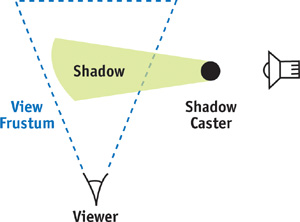
Figure 15-1 Objects Not in the Visible Set Can Influence the Rendered Scene
At this point, we have defined all the sets we need for rendering with per-pixel lighting. First set V is generated from the camera and rendered for the ambient pass. Next is the rendering of each light. For each light, set L is determined and from this, sets I and S are generated. Set S determines the shadowing term for the light, and then each object in set I is rendered to apply the lighting.
Now we discuss the details of efficiently generating each set.
15.4 Generating Sets
Theory is great, but small details can make the difference between high stress and high frame rates. So in this section, we cover the fine points of generating each set introduced in the preceding section, with practical application in mind.
15.4.1 The Visible Set
The lights and the viewport each need to generate a visible set. But how tight should the visible set be? And how much processor time should be spent determining these sets? The answers depend on the type of application being developed. However, at the very minimum, the visibility determination algorithm should perform frustum-level culling and a fair amount of object-level occlusion. The reason for this requirement is simply a matter of scale. If a standard visible set contains ten objects in the frustum and 30 percent of the objects are occluded, three objects can be dropped.
Let's factor in the lights as well, because we will be using visibility for the lights in the scene. If each light has similar statistics for occlusion, then in realistic scenes we can avoid rendering dozens or even hundreds of objects per frame. So the level of occlusion within a frustum should be carefully considered when determining the visibility system for a per-pixel lighting renderer. From there, it is simply a balancing act to determine the best ratio of CPU time to occlusion.
15.4.2 The Lights Set
Determining this set is nearly identical to determining the visible set. However, point lights can cause problems for visibility algorithms that perform any sort of projection onto a plane. A point light has a full spherical field of view, so it cannot be mapped easily onto a plane, something that many visibility algorithms rely on. One solution to this problem is to place a cube around a light and then perform the visibility test once for each face of the cube, from the point of view of the light. This method can become very expensive, though, because it requires doing the visibility determination once for each of the six faces; care must be taken not to add the same object to the visible set multiple times if it is seen by multiple faces. As a general rule, examine the visibility system, and if it uses any form of projection onto a plane, consider switching to a visibility system that works without any projections, or implementing a separate visibility system exclusively for the point-light visibility queries.
15.4.3 The Illumination Set
Fast set operations are critical for efficiently determining the illumination set. There are two approaches to implementing the necessary set operations: (1) have sets that know which objects they contain and (2) have objects that know which sets they belong to.
The first approach uses sorted lists that contain references to all the objects within that set. The lists must be sorted to allow for determining intersections and unions in linear time through merging, but the sorting can be based on whatever criteria are appropriate. This implementation can be difficult to perform efficiently because it involves sorting, merging, and occasionally searching, but for some applications, it works well if these sets are already needed for other operations. Using this approach, determining the illumination set would simply be a matter of determining sets V and L and then finding the elements contained within both sets.
The second approach works particularly well for per-pixel lighting, where a fixed number of sets that the object belongs to can be stored as flags on the object. Then instead of building a set, we perform operations on the list of objects. To build the visible set, we find all the objects in view and flag them as belonging to the visible set. To determine the set L, we perform a similar process, but we flag the objects as being in the lighting group. Then set I is found simply by looking through the list of objects that the light can see and finding the objects that are also flagged as being in the visible set. The implementation of this second approach is much simpler than that of the first, but the flags do need to be reset after the operation is complete.
15.4.4 The Shadow Set
Shadow calculation is more difficult than the other operations because it involves operations on volumes extruded by a light. Often objects are represented with a bounding box or a bounding sphere that encompasses the visible geometry. The volume of space that the shadow of an object affects is determined by extruding each point of the primitive along the vector to the light, to the point where the distance to the light is equal to the radius of the light. Therefore, the shadow set must include all objects that, when extruded from the light up to the effective light radius, intersect the view frustum.
Shadows for Lights Inside a Frustum
Lights always project shadows away from the position of the light. Therefore, if a light is located within the view frustum, it is safe to discard from the shadow set any object that is outside the view frustum. This is because if a light is inside a convex volume and an object is outside the volume, the object will always be extruded away from the convex volume and therefore cannot intersect the frustum.
We need to use the set of all objects in the view frustum to determine which objects cast shadows, not the visible set V, which is only a subset of the objects in the view frustum. The set V may have occluded objects that are not directly visible but can still cast shadows into visible regions, as illustrated in Figure 15-2. Therefore, a new set, called set F, is defined for all objects in the view frustum without any occlusion. If the light is in the frustum, then the shadow set S is defined as the intersection of sets F and L.
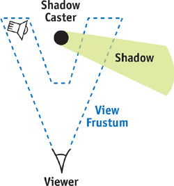
Figure 15-2 An Object Not in the Visible Set but in the Frustum, Casting Shadows
Shadows for Lights Outside a Frustum
Unfortunately, lights outside a frustum are not simple, because the light can project objects that are outside the view frustum into the view frustum. However, this occurs only within a certain region of space defined as the convex hull around the view frustum and the point of the light source (Everitt and Kilgard 2003). Once this convex hull is determined, detecting whether an object needs to cast a shadow is simply a matter of seeing if it overlaps this convex space.
The trick to this approach is to quickly determine the convex hull around the view frustum and the light position. This is a constrained case of adding a point to an already convex hull, so a simple solution can be used. The frustum begins as six planes defining a convex region of space, with the planes defining an inside half-space that includes the frustum and an outside half-space. Our goal is to create a volume that encloses the area that would be covered if lines were connected from the light source to every point contained within the view frustum volume. Figure 15-3 illustrates the process.
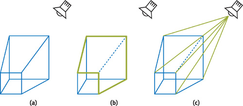
Figure 15-3 Creating the Convex Hull Around the Light and View Frustum
The final convex hull will consist of any planes from the original view frustum where the light is contained within the inside half-space of the plane. In addition, it will consist of a plane for each silhouette edge that passes through the edge and the light. These silhouette edges are simply edges where the light is on the inside half-space of one of the touching planes, and in the outside half-space of the other plane. Both can be found simply and efficiently, but the view frustum will need some extra data in addition to just these planes. This data is a listing of:
- The edges in the view frustum
- The two points used by each edge in the view frustum
- An edge count that is used for detecting silhouette edges with respect to the light
- A mapping that indicates which edges each frustum plane partially defines
- A winding order for each edge with respect to each plane that touches the edge
For each plane of the view frustum, the position of the light is checked. If the light position is on the same side of the plane as the view frustum, that plane can be used directly in the convex hull. However, if the light position is on the opposite side of the view frustum, the plane must be discarded. At this point, the edge count of each edge that the plane affects must be incremented. Once this is done for all planes of the view frustum, there will be a listing of planes to use and a count for each edge in the view frustum.
The edge count serves the role of detecting the silhouette edge. If the count is zero, the light position was inside both defining planes, and there is no silhouette cast from that edge. If it is more than one, the light was outside both defining planes, and again there is no contributing silhouette edge. If an edge in the view frustum has a count of one, this indicates a silhouette edge from the perspective of the light, meaning that a plane must be generated that includes the light position and both points of the edge. The generation of this plane is where the winding order of the edges comes in. Whatever plane the light is outside of should store the winding order of the edge with that edge. The winding order should flag whether the edge is winding clockwise or counterclockwise with respect to the facing of the plane, and it is used to ensure that the resulting plane will be facing the correct direction. This is needed because two planes define the edge, and it is impossible to lay out all the edges so that the winding order is consistent with respect to all planes defining it.
The silhouette edge portion of the algorithm results in a frustum that extrudes from the point of view of the light and outlines the frustum with respect to the light. This volume would stretch on forever, but it is bound by the planes that contain the light in the inside half-space, effectively forming a cap and resulting in a convex hull around the frustum and the light.
This pseudocode can quickly generate the convex hull:
 Initialize all edge counts to zero
For each plane
If the light is on the inside
Add the plane to the final plane list
Else
For each edge the plane partially defines
Increment the edge count
Store the winding for this edge
For each edge
If the edge count is equal to one
Add a plane that includes the edge and the light point,
flipping the plane normal if the winding is reversed
15.5 Visibility for Fill Rate
Visibility can be used effectively to improve performance not only on the CPU, but also on the GPU. When we perform per-pixel lighting with stencil volumes, the fill rate consumed—by filling in stencil volumes or by rendering large objects multiple times—can quickly become a bottleneck. The best way to combat this bottleneck is to restrict the area that the card can render to by using a scissor rectangle. On the most recent NVIDIA cards, the scissor rectangle concept can be extended even further, to a depth test that acts like a z-scissor range and effectively emulates a scissor frustum in space.
To create a scissor rectangle, project the dimensions of the light onto the screen and restrict rendering to that region. However, on even medium-size lights, this method quickly loses most benefits because the light covers the majority of the screen. It becomes particularly inefficient in tight areas with large lights. In this situation, the lights do not affect a large portion of the screen; however, because of their radii, a naive implementation has a much larger scissor rectangle than necessary. Picture a ventilation shaft with a light that shines down most of the shaft. To illuminate this large area, the light must have a large radius, which leads to a large scissor rectangle—even though it is lighting only the shaft, which might be a small portion of the screen.
To ensure that the scissor rectangle is as tight as possible, we can use the sets that were outlined earlier. We already have the listing of objects that the light will influence when it is rendered. And we can determine the bounding rectangle of a primitive projected onto the screen. So we can find a very tight scissor rectangle by this method: Project each object that is affected by the light onto the screen, find the total bounding box of those objects, and perform an intersection with the projected bounding box for the light itself. It's best to use low-level primitives (such as bounding spheres or axis-aligned bounding boxes) for these projections because they can be costly and there's little benefit in increasing the tightness of the bounding primitives.
By performing these operations—even if a light has a huge radius—we create a scissor rectangle that is never larger than the area of the objects the light affects projected on the screen. This approach can dramatically reduce fill and greatly help keep frame rates consistent across scenes.
15.6 Practical Application
All the techniques mentioned in this chapter were implemented in an existing system and yielded significant performance improvements. The visibility solution was a portal visibility scheme, which allowed the use of the same visibility system for the viewer and the lights.
Table 15-1 shows the number of frames per second in a normalized form, as well as the number of batches required from various scenes, with different components enabled. For each scene, the frame rate is normalized and is shown when (a) no visibility is used; (b) visibility only for the camera is used; (c) visibility for lights and camera is used; (d) visibility for lights, camera, and shadow is used; and (e) scissor rectangles are added.
Table 15-1. The Effects of Different Visibility Techniques on Performance
|
Scene 1 |
Normalized Frame Rate |
Batches |
|
Frustum-based visibility |
0.87 |
1171 |
|
Visibility occlusion |
0.92 |
492 |
|
Lighting occlusion |
0.99 |
468 |
|
Shadow occlusion |
0.99 |
460 |
|
Scissor rectangle |
1.00 |
460 |
|
Scene 2 |
Normalized Frame Rate |
Batches |
|
Frustum-based visibility |
0.56 |
1414 |
|
Visibility occlusion |
0.80 |
521 |
|
Lighting occlusion |
0.98 |
438 |
|
Shadow occlusion |
0.98 |
437 |
|
Scissor rectangle |
1.00 |
437 |
As Table 15-1 affirms, the introduction of visibility into a scene can dramatically improve frame rate. Further testing of the scene showed that after a certain point, the application became fill-rate-limited, and performance improvements from the visibility were due to occlusion that resulted in fewer objects for the video card to rasterize.
15.7 Conclusion
The high number of batches and large amount of fill rate that per-pixel lighting requires means that we need to minimize the number of rendered objects and the area of the screen they affect. By using any standard visibility algorithm and the techniques illustrated in this chapter, we can substantially improve performance.
15.8 References
Akenine-Möller, Tomas, and Eric Haines. 2002. Real-Time Rendering, 2nd ed. A. K. Peters. See the discussion of visibility algorithms on pp. 345–389.
Everitt, Cass, and Mark J. Kilgard. 2003. "Optimized Stencil Shadow Volumes." Presentation at Game Developers Conference 2003. Available online at http://developer.nvidia.com/docs/IO/8230/GDC2003_ShadowVolumes.pdf
Wloka, Matthias. 2003. "Batch, Batch, Batch: What Does It Really Mean?" Presentation at Game Developers Conference 2003. Available online at http://developer.nvidia.com/docs/IO/8230/BatchBatchBatch.pdf
Copyright
Many of the designations used by manufacturers and sellers to distinguish their products are claimed as trademarks. Where those designations appear in this book, and Addison-Wesley was aware of a trademark claim, the designations have been printed with initial capital letters or in all capitals.
The authors and publisher have taken care in the preparation of this book, but make no expressed or implied warranty of any kind and assume no responsibility for errors or omissions. No liability is assumed for incidental or consequential damages in connection with or arising out of the use of the information or programs contained herein.
The publisher offers discounts on this book when ordered in quantity for bulk purchases and special sales. For more information, please contact:
U.S. Corporate and Government Sales
(800) 382-3419
corpsales@pearsontechgroup.com
For sales outside of the U.S., please contact:
International Sales
international@pearsoned.com
Visit Addison-Wesley on the Web: www.awprofessional.com
Library of Congress Control Number: 2004100582
GeForce™ and NVIDIA Quadro® are trademarks or registered trademarks of NVIDIA Corporation.
RenderMan® is a registered trademark of Pixar Animation Studios.
"Shadow Map Antialiasing" © 2003 NVIDIA Corporation and Pixar Animation Studios.
"Cinematic Lighting" © 2003 Pixar Animation Studios.
Dawn images © 2002 NVIDIA Corporation. Vulcan images © 2003 NVIDIA Corporation.
Copyright © 2004 by NVIDIA Corporation.
All rights reserved. No part of this publication may be reproduced, stored in a retrieval system, or transmitted, in any form, or by any means, electronic, mechanical, photocopying, recording, or otherwise, without the prior consent of the publisher. Printed in the United States of America. Published simultaneously in Canada.
For information on obtaining permission for use of material from this work, please submit a written request to:
Pearson Education, Inc.
Rights and Contracts Department
One Lake Street
Upper Saddle River, NJ 07458
Text printed on recycled and acid-free paper.
5 6 7 8 9 10 QWT 09 08 07
5th Printing September 2007
- Contributors
- Copyright
- Foreword
- Part I: Natural Effects
-
- Chapter 1. Effective Water Simulation from Physical Models
- Chapter 2. Rendering Water Caustics
- Chapter 3. Skin in the "Dawn" Demo
- Chapter 4. Animation in the "Dawn" Demo
- Chapter 5. Implementing Improved Perlin Noise
- Chapter 6. Fire in the "Vulcan" Demo
- Chapter 7. Rendering Countless Blades of Waving Grass
- Chapter 8. Simulating Diffraction
- Part II: Lighting and Shadows
-
- Chapter 9. Efficient Shadow Volume Rendering
- Chapter 10. Cinematic Lighting
- Chapter 11. Shadow Map Antialiasing
- Chapter 12. Omnidirectional Shadow Mapping
- Chapter 13. Generating Soft Shadows Using Occlusion Interval Maps
- Chapter 14. Perspective Shadow Maps: Care and Feeding
- Chapter 15. Managing Visibility for Per-Pixel Lighting
- Part III: Materials
- Part IV: Image Processing
- Part V: Performance and Practicalities
-
- Chapter 28. Graphics Pipeline Performance
- Chapter 29. Efficient Occlusion Culling
- Chapter 30. The Design of FX Composer
- Chapter 31. Using FX Composer
- Chapter 32. An Introduction to Shader Interfaces
- Chapter 33. Converting Production RenderMan Shaders to Real-Time
- Chapter 34. Integrating Hardware Shading into Cinema 4D
- Chapter 35. Leveraging High-Quality Software Rendering Effects in Real-Time Applications
- Chapter 36. Integrating Shaders into Applications
- Part VI: Beyond Triangles
- Preface