
GPU Gems
GPU Gems is now available, right here, online. You can purchase a beautifully printed version of this book, and others in the series, at a 30% discount courtesy of InformIT and Addison-Wesley.
The CD content, including demos and content, is available on the web and for download.
Chapter 3. Skin in the "Dawn" Demo
Curtis Beeson
NVIDIA
Kevin Bjorke
NVIDIA
3.1 Introduction
"Dawn" is a demonstration that was created by NVIDIA to introduce the GeForce FX product line and illustrate how programmable shading could be used to create a realistic human character, as shown in Figure 3-1. The vertex shaders (described in Chapter 4, "Animation in the 'Dawn' Demo") deform a high-resolution mesh through indexed skinning and blend shapes, and they provide setup for the lighting model used in the fragment shaders. The skin and wing fragment shaders produce both range and detail that could not have been achieved before the introduction of programmable graphics hardware. [1]
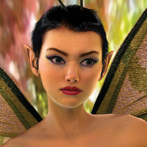
Figure 3-1 Dawn
This chapter discusses how programmable graphics hardware was used to light and accelerate the skin shader on the Dawn character in the demo.
3.2 Skin Shading
Skin is a difficult surface to simulate in computer graphics for a variety of reasons. Even the high-end production graphics used in movies are unable to simulate a photorealistic human character that can withstand close examination. Humans gain a great deal of information with nonverbal cues: the shifting of weight, the particular way of walking, facial expressions, and even the blush of someone's skin. Researchers have shown that babies recognize and gaze at facial expressions within moments of birth. We humans are therefore very perceptive when it comes to detecting irregularities in the way characters move and emote, and in the subtle coloring of their skin. Although few people may understand terms such as subsurface scattering and rim lighting, almost anybody can tell you when your rendering got them wrong.
In addition to shading issues, people may be quick to say that a skin shader looks like plastic because of the way the skin moves, so it is important to address the problems of character setup. Chapter 4 describes those techniques used in the "Dawn" demo for driving the body using accumulated indexed skinning, and for adding emotion to Dawn's face through blend targets. These techniques provide a passable approximation for Dawn and for the actions she needs to perform, but they might fail to fully describe the way skin slides, flexes, and sags over a real skeleton for other purposes. When creating a character, it's important to model both the rigging and the shading appropriately for the range of views that the observer will actually see.
3.3 Lighting the Scene
Once the skin is moving in as realistic a manner as possible, you can focus on the shading. The most straightforward way to break down the shading of a surface is to examine the lighting environment of the scene and then look at the skin's response to that light.
3.3.1 A High-Dynamic-Range Environment
We wanted to create our character and place her in a setting that defied the sort of flat, simple-looking shading that typifies traditional real-time graphics techniques. Older graphics architectures were built around the concepts of Gouraud and Phong shading, which describe all incoming light as radiating from infinitely small point, directional, and spot lights. The diffuse and specular responses of material surfaces were usually described using textures and equations that failed to describe a suitable range of light response.
One undesirable result of the previous approach is that scenes tended to lack the brightness range seen in the real world. A white piece of paper on the floor would be as bright as a white light source above; characters in complex environments often looked out of place because they were lit by discrete points instead of by their surroundings.
Paul Debevec has done a great deal of research in the area of high-dynamic-range image processing and manipulation to address exactly this problem. His work can be found in a variety of SIGGRAPH publications and is made more tangible through examples in his rendered films. [2] We sought to take advantage of the new programmable real-time graphics architectures to apply these concepts to a real-time character. In particular, we wished to have Dawn lit by the environment and to allow the bright spots to cause light to bleed and soften her silhouette edges.
Dawn being a fairy, we found a suitable woodsy area and took a number of calibrated pictures. We used an iPIX kit that included a tripod that locks at opposite angles, a digital camera, and a 183-degree fish-eye lens. In this case, the two hemispherical pictures were taken across several shutter speeds using one of the camera's built-in macros. This collection of images provides better information about the light intensities at each pixel, as opposed to the single pixel color produced at any individual shutter speed.
We used the iPIX software to stitch the corresponding hemispheres into a single panorama, and then we used Debevec's HDRShop software to create a high-dynamic-range panorama that encodes the light color and intensity of the environment at every given angle. See Figure 3-2. HDRShop can then create a diffuse lookup map that performs a convolution to create a diffuse or specular map for a surface with a given surface roughness (which in the past would have been modeled using a Phong exponent).
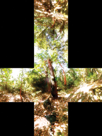
Figure 3-2 The Cube Map of the Environment
The diffuse map is a cube map, as shown in Figure 3-3, indexed using the surface normal of the mesh, and it stores a cosine-weighted average of the incoming light for that direction. Ignoring for now the fact that parts of the hemisphere may be occluded at a given point, this weighted average gives the appropriate value for computing diffuse reflection for points on the surface.
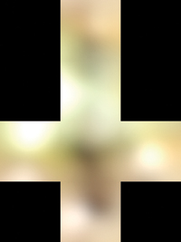
Figure 3-3 The Diffuse Cube Environment Map
The specular map is also a cube map, as shown in Figure 3-4, and is indexed using the reflection vector (the way "usual" cube maps are used for reflections). This specular map is blurred based on the roughness factor to simulate the changing surface normal at any given point on the surface.
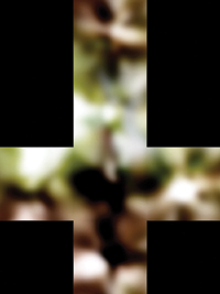
Figure 3-4 The Specular Cube Environment Map
3.3.2 The Occlusion Term
One problem with using environment maps to describe an environment or a lighting solution is that the mapped samples are really accurate for only a single point in space. The first side effect of this is that if the fairy walks around, the background appears to be "infinitely" far away. This was a suitable approximation for us, because the fairy is small and the background should look far away in this instance. [3]
The second side effect is that the diffuse and specular maps describe the incident light from the environment that was photographed, but they do nothing to describe the shadows introduced by simulated elements such as Dawn herself. Thus, it was necessary to develop a technique to incorporate this information.
Many real-time shadowing techniques produce hard shadows, and we wanted a particularly soft look. Thus, we generated an occlusion term that approximated what percentage of the hemisphere above each vertex was obstructed by other objects in the scene. [4]
This was done using a custom software tool that casts rays stochastically over that vertex's visible hemisphere and found collisions with other geometry. We used this technique in the "Dawn" demo and in the "Ogre" demo (content courtesy of Spellcraft Studio), though the results were then used differently. For Dawn, the occlusion term was kept constant for the vertices of her figure; her face used a blend of occlusion terms from the various morph targets.
Having reached the limits of what we could do on a prerelease GeForce FX 5800 (Dawn was created to be a launch demo for that product), we stopped shy of animating the occlusion term for every vertex on every frame, as we did for the Ogre character in Spellcraft Studio's "Yeah! The Movie" demo.
3.4 How Skin Responds to Light
Skin is unlike most surfaces that we model in computer graphics because it is composed of layers of semitranslucent epidermis, dermis, and subcutaneous tissue. Subsurface scattering is the term we give to the phenomenon whereby light enters the surface, scatters through the medium, and exits at another point. This effect can commonly be seen as an orange glow of light passing through the skin when you hold your hand up in front of the Sun. This scattering under the skin is important to skin's appearance at all angles and helps give it a soft, highly distinctive character. Unfortunately, this reality defies a common assumption in graphics APIs and architectures: namely, light at one point on an object doesn't affect reflection at other points.
In the past, some groups have tried to emulate skin's complexity using multiple, layered texture maps. In general this approach has proven to be difficult to manage and difficult for the texture artists to work with as they previsualize the final blended color. Instead, we used a single color map, with color variations added through the shading, as shown in Figure 3-5.
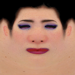
Figure 3-5 The Diffuse Color Map for the Front Half of Dawn's Head
Furthermore, skin has extremely fine variations that affect its reflective properties. These have subtle effects on skin's appearance, particularly when the light is directly opposite the camera position—that is, edge and rim lighting. Real skin has tiny features such as vellus hairs and pores that catch the light. These details were too small for us to model explicitly, but we wanted a surface that still gave us an appropriate overall look. Adding a bump map provided some additional detail when seen in close-up—particularly for small wrinkles—but we wanted a soft appearance, not shiny, stippled plastic, and we wanted the effects to be visible regardless of the size on screen (bump maps are usually visible only when seen up close).
We approximated both of these shading attributes by recognizing that we could model them as simple formulas based on the surface normal and the lighting or viewing vectors. In particular, along silhouette edges we sampled the lighting from behind Dawn, as indexed by the view vector—mixing the light coming "through" Dawn with her base skin tones to create the illusion of subsurface and edge-effect lighting, particularly for very bright areas in the background map. See Figure 3-6.
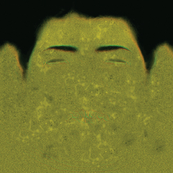
Figure 3-6 The Tangent-Space Normal Map (Bump Map) for the Front of Dawn's Head
3.5 Implementation
The processes of lighting are split between the vertex and the fragment shaders. This is a one-pass lighting solution: no additional render passes or alpha blending is required to create the skin surface.
3.5.1 The Vertex Shader
The primary functions of the vertex shader are to transform the coordinate into projection space and to perform those mathematical operations that are prohibitively expensive to compute in the fragment shader. As mentioned in Section 3.3.2, the vertex shader in the "Dawn" demo first applied morph targets (if any), and then skinned the mesh of over 180,000 vertices with a skeleton of 98 bones. See Chapter 4 for more.
For each vertex, we receive from the CPU application the data shown in Listing 3-1. [5]
The factors that are computed in the vertex shader and passed as interpolated values in the fragment shader include the world-space eye direction vector (worldEyeDirection), describing the direction from the viewer's eye to any given vertex; the 3x3 tangent to world-space matrix (tangentToWorld) [6] ; and a variety of terms collectively called blood transmission terms (bloodTransmission). Listing 3-2 shows the data structure of the output vertices.
Example 3-1. The Per-Vertex Data Received from the CPU Application
// Here is the PER-VERTEX data -- we use 16 vectors,
// the maximum permitted by our graphics API
struct a2vConnector
{
  float4 coord;
  // 3D location
  float4 normal;
  float4 tangent;
  float3 coordMorph0;
  // 3D offset to target 0
  float4 normalMorph0;
  // matching offset
  float3 coordMorph1;
  // 3D offset to target 1
  float4 normalMorph1;
  // matching offset
  float3 coordMorph2;
  // 3D offset to target 2
  float4 normalMorph2;
  // matching offset
  float3 coordMorph3;
  // 3D offset to target 3
  float4 normalMorph3;
  // matching offset
  float3 coordMorph4;
  // 3D offset to target 4
  float4 normalMorph4;
  // matching offset
  float4 boneWeight0_3;
  // skull and neck bone
  float4 boneIndex0_3;
  // indices and weights
  float4 skinColor_frontSpec;
  // UV indices
};
Example 3-2. The Data Structure of the Output Vertices
// Here is the data passed from the vertex shader
// to the fragment shader
struct v2fConnector
{
  float4 HPOS : POSITION;
  float4 SkinUVST : TEXCOORD0;
  float3 WorldEyeDir : TEXCOORD2;
  float4 SkinSilhouetteVec : TEXCOORD3;
  float3 WorldTanMatrixX : TEXCOORD5;
  float3 WorldTanMatrixY : TEXCOORD6;
  float3 WorldTanMatrixZ : TEXCOORD7;
};
Because we are bump mapping, our fragment shader will have to find the world-space bumped normal, so we must provide it a way to get from the tangent-space bumped normal (provided by a texture map) into world space. The common way of doing bump mapping is to have the vertex shader pass the world-space normal, binormal, and tangent, and then to use these three vectors as a 3x3 matrix to rotate vectors from world space into tangent space for computation. In this case, the fragment shader will have to look into the lighting solution using the world-space vectors, so we map the transpose of this matrix (the transpose is the inverse for a rotation matrix), resulting in nine MOV instructions in the vertex shader to load the WorldTanMatrixX, WorldTanMatrixY, and WorldTanMatrixZ terms.
Finally, the vertex shader blood transmission or "skin silhouette" terms are a float4 vector, composed of the occlusion term; different variations on the expression (N · V) (that is, the dot product of the surface normal and the view vector); and a rotation of the normal against the coordinate system of the cube map lighting. See Figure 3-7.
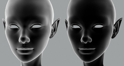
Figure 3-7 Dot Products Stored in
OUT.SkinSilhouetteVec =
    float4(objectNormal.w, oneMinusVdotN *oneMinusVdotN, oneMinusVdotN,
           vecMul(G_DappleXf, worldNormal.xyz).z);
These steps provided just a few ways of parameterizing how near a silhouette the pixel was, and they gave us a toy box of values to play with while developing the fragment shader. Mathematically astute readers may notice that the (N · V) terms may not interpolate correctly on large triangles via Gouraud (linear) shading. Fortunately for this specific case, Dawn is finely tessellated, and the camera needs to be very near her face before any error is apparent. This is a good example of using a shader that is highly specific to a particular model, to be seen in a range of predictable screen sizes. The (N · V) could have been done in the fragment shader, but that would have made for a significantly more expensive (and hence slower) shader.
Note that all of the vertex shaders in the "Dawn" demo were procedurally generated. We assign fragment shaders in Maya, and we have a vertex shader generator that looks at the character setup (skeletons, morph targets, and so on) and the inputs requested by the fragment shader; it then generates the optimal vertex shader from a rules file using an A* search. [7]
Listing 3-3 is a sample annotated vertex shader, as used on Dawn's face area (incorporating both matrix skinning and shape blends, along with values used for the color calculations in the fragment shader).
Example 3-3. A Sample Vertex Shader for Dawn's Face
// Helper function:
// vecMul(matrix, float3) multiplies like a vector
// instead of like a point (no translate)
float3 vecMul(const float4x4 matrix, const float3 vec)
{
  return (float3(dot(vec, matrix._11_12_13), dot(vec, matrix._21_22_23),
                 dot(vec, matrix._31_32_33)));
}
// The Vertex Shader for Dawn's Face
v2fConnector faceVertexShader(
    a2vConnector IN, const uniform float MorphWeight0,
    const uniform float MorphWeight1, const uniform float MorphWeight2,
    const uniform float MorphWeight3, const uniform float MorphWeight4,
    const uniform float4x4 BoneXf[8], const uniform float4 GlobalCamPos,
    const uniform float4x4 ViewXf, const uniform float4x4 G_DappleXf,
    const uniform float4x4 ProjXf)
{
  v2fConnector OUT;
  // The following large block is entirely
  // concerned with shape skinning.
  // First, do shape blending between the five
  // blend shapes ("morph targets")
  float4 objectCoord = IN.coord;
  objectCoord.xyz += (MorphWeight0 * IN.coordMorph0);
  objectCoord.xyz += (MorphWeight1 * IN.coordMorph1);
  objectCoord.xyz += (MorphWeight2 * IN.coordMorph2);
  objectCoord.xyz += (MorphWeight3 * IN.coordMorph3);
  objectCoord.xyz += (MorphWeight4 * IN.coordMorph4);
  // Now transform the entire head by the neck bone
  float4 worldCoord =
      IN.boneWeight0_3.x * mul(BoneXf[IN.boneIndex0_3.x], objectCoord);
  worldCoord +=
      (IN.boneWeight0_3.y * mul(BoneXf[IN.boneIndex0_3.y], objectCoord));
  worldCoord +=
      (IN.boneWeight0_3.z * mul(BoneXf[IN.boneIndex0_3.z], objectCoord));
  worldCoord +=
      (IN.boneWeight0_3.w * mul(BoneXf[IN.boneIndex0_3.w], objectCoord));
  // Repeat the previous skinning ops
  // on the surface normal
  float4 objectNormal = IN.normal;
  objectNormal += (MorphWeight0 * IN.normalMorph0);
  objectNormal += (MorphWeight1 * IN.normalMorph1);
  objectNormal += (MorphWeight2 * IN.normalMorph2);
  objectNormal += (MorphWeight3 * IN.normalMorph3);
  objectNormal += (MorphWeight4 * IN.normalMorph4);
  objectNormal.xyz = normalize(objectNormal.xyz);
float3 worldNormal = IN.boneWeight0_3.x *
vecMul(BoneXf[IN.boneIndex0_3.x],
objectNormal.xyz));
worldNormal +=
    (IN.boneWeight0_3.y * vecMul(BoneXf[IN.boneIndex0_3.y], objectNormal.xyz));
worldNormal +=
    (IN.boneWeight0_3.z * vecMul(BoneXf[IN.boneIndex0_3.z], objectNormal.xyz));
worldNormal +=
    (IN.boneWeight0_3.w * vecMul(BoneXf[IN.boneIndex0_3.w], objectNormal.xyz));
worldNormal = normalize(worldNormal);
// Repeat the previous skinning ops
// on the orthonormalized surface tangent vector
float4 objectTangent = IN.tangent;
objectTangent.xyz =
    normalize(objectTangent.xyz -
              dot(objectTangent.xyz, objectNormal.xyz) * objectNormal.xyz);
float4 worldTangent;
worldTangent.xyz =
    IN.boneWeight0_3.x * vecMul(BoneXf[IN.boneIndex0_3.x], objectTangent.xyz);
worldTangent.xyz +=
    (IN.boneWeight0_3.y * vecMul(BoneXf[IN.boneIndex0_3.y], objectTangent.xyz));
worldTangent.xyz +=
    (IN.boneWeight0_3.z * vecMul(BoneXf[IN.boneIndex0_3.z], objectTangent.xyz));
worldTangent.xyz +=
    (IN.boneWeight0_3.w * vecMul(BoneXf[IN.boneIndex0_3.w], objectTangent.xyz));
worldTangent.xyz = normalize(worldTangent.xyz);
worldTangent.w = objectTangent.w;
// Now our deformations are done.
// Create a binormal vector as the cross product
// of the normal and tangent vectors
float3 worldBinormal =
    worldTangent.w * normalize(cross(worldNormal, worldTangent.xyz));
// Reorder these values for output as a 3 x 3 matrix
// for bump mapping in the fragment shader
OUT.WorldTanMatrixX = float3(worldTangent.x, worldBinormal.x, worldNormal.x);
OUT.WorldTanMatrixY = float3(worldTangent.y, worldBinormal.y, worldNormal.y);
OUT.WorldTanMatrixZ = float3(worldTangent.z, worldBinormal.z, worldNormal.z);
// The vectors are complete. Now use them
// to calculate some lighting values
float4 worldEyePos = GlobalCamPos;
OUT.WorldEyeDir = normalize(worldCoord.xyz - worldEyePos.xyz);
float4 eyespaceEyePos = {0.0f, 0.0f, 0.0f, 1.0f};
float4 eyespaceCoord = mul(ViewXf, worldCoord);
float3 eyespaceEyeVec = normalize(eyespaceEyePos.xyz - eyespaceCoord.xyz);
float3 eyespaceNormal = vecMul(ViewXf, worldNormal);
float VdotN = abs(dot(eyespaceEyeVec, eyespaceNormal));
float oneMinusVdotN = 1.0 - VdotN;
OUT.SkinUVST = IN.skinColor_frontSpec;
OUT.SkinSilhouetteVec =
    float4(objectNormal.w, oneMinusVdotN * oneMinusVdotN, oneMinusVdotN,
           vecMul(G_DappleXf, worldNormal.xyz).z);
float4 hpos = mul(ProjXf, eyespaceCoord);
OUT.HPOS = hpos;
return OUT;
}
3.5.2 The Fragment Shader
Given the outputs of the vertex shader (and everywhere on Dawn's body, the vertex shaders output a consistent data structure), we can generate the actual textured colors.
Listing 3-4 shows the complete fragment shader as used by the face.
Example 3-4. The Fragment Shader for Dawn's Face
float4 faceFragmentShader(
    v2fConnector IN, uniform sampler2D SkinColorFrontSpecMap,
    uniform sampler2D SkinNormSideSpecMap,
    // xyz normal map
    uniform sampler2D SpecularColorShiftMap, // and spec map in "w"
    uniform samplerCUBE DiffuseCubeMap, uniform samplerCUBE SpecularCubeMap,
    uniform samplerCUBE HilightCubeMap)
    : COLOR
{
  half4 normSideSpec tex2D(SkinNormSideSpecMap, IN.SkinUVST.xy);
  half3 worldNormal;
  worldNormal.x = dot(normSideSpec.xyz, IN.WorldTanMatrixX);
  worldNormal.y = dot(normSideSpec.xyz, IN.WorldTanMatrixY);
  worldNormal.z = dot(normSideSpec.xyz, IN.WorldTanMatrixZ);
  fixed nDotV = dot(IN.WorldEyeDir, worldNormal);
  half4 skinColor = tex2D(SkinColorFrontSpecMap, IN.SkinUVST.xy);
  fixed3 diffuse = skinColor * texCUBE(DiffuseCubeMap, worldNormal);
  diffuse = diffuse * IN.SkinSilhouetteVec.x;
  fixed4 sideSpec = normSideSpec.w * texCUBE(SpecularCubeMap, worldNormal);
  fixed3 result = diffuse * IN.SkinSilhouetteVec.y + sideSpec;
  fixed3 hilite = 0.7 * IN.SkinSilhouetteVec.x * IN.SkinSilhouetteVec.y *
                  texCUBE(HilightCubeMap, IN.WorldEyeDir);
  fixed reflVect = IN.WorldEyeDir * nDotV - (worldNormal * 2.0x);
  fixed4 reflColor =
      IN.SkinSilhouetteVec.w * texCUBE(SpecularCubeMap, reflVect);
  result += (reflColor.xyz * 0.02);
  fixed hiLightAttenuator = tex2D(SpecularColorShiftMap, IN.SkinUVST.xy).x;
  result += (hilite * hiLightAttenuator);
  fixed haze = reflColor.w * hiLightAttenuator;
  return float4(result.xyz, haze);
}
First, we get bump-mapped surface normal. The texture stored in SkinNormSideSpecMap contains tangent-space normals in its RGB components, and the specular map—a grayscale representing highlight intensities—is piggybacking in the alpha channel (we'll refer to the component RGB as xyz here for code clarity). By rotating the tangent-space xyz values against the WorldTanMatrix, we recast them in world coordinates—exactly what we need to perform our world-space lighting algorithm.
We then compare the newly calculated surface normal to the view direction. We use this nDotV value later.
half4 normSideSpec tex2D(SkinNormSideSpecMap, IN.SkinUVST.xy);
half3 worldNormal;
worldNormal.x = dot(normSideSpec.xyz, IN.WorldTanMatrixX);
worldNormal.y = dot(normSideSpec.xyz, IN.WorldTanMatrixY);
worldNormal.z = dot(normSideSpec.xyz, IN.WorldTanMatrixZ);
fixed nDotV = dot(IN.WorldEyeDir, worldNormal);
Diffuse color is the skin texture map, multiplied by the preconvolved diffuse-lighting cube map. We modulate this a bit by the hemispherical occlusion term passed in SkinSilhouetteVec.
half4 skinColor = tex2D(SkinColorFrontSpecMap, IN.SkinUVST.xy);
fixed3 diffuse = skinColor * texCUBE(DiffuseCubeMap, worldNormal);
diffuse = diffuse * IN.SkinSilhouetteVec.x;
Edge specular color comes from our specular cube map, modulated by the specular intensity map that we got with the normal map (that is, in the alpha channel of SkinNormSideSpecMap). We start building a cumulative result.
fixed4 sideSpec = normSideSpec.w * texCUBE(SpecularCubeMap, worldNormal);
fixed3 result = diffuse * IN.SkinSilhouetteVec.y + sideSpec;
Next, we retrieve the color of the environment behind Dawn, by indexing on WorldEyeDir, and we get the traditional reflection cube-map color. Add these, along with some artistic "fudge factoring," to our result.
fixed3 hilite = 0.7 * IN.SkinSilhouetteVec.x * IN.SkinSilhouetteVec.y *
                texCUBE(HilightCubeMap, IN.WorldEyeDir);
fixed reflVect = IN.WorldEyeDir * nDotV - (worldNormal * 2.0x);
fixed4 reflColor = IN.SkinSilhouetteVec.w * texCUBE(SpecularCubeMap, reflVect);
result += (reflColor.xyz * 0.02);
fixed hiLightAttenuator = tex2D(SpecularColorShiftMap, IN.SkinUVST.xy).x;
result += (hilite * hiLightAttenuator);
Finally, we add a little extra silhouette information into the alpha channel of the final output, so that the "bloom" along Dawn's silhouette edges looks more natural when alpha blending.
fixed haze = reflColor.w * hiLightAttenuator;
return float4(result.xyz, haze);
3.6 Conclusion
Although many of the implementation details in the Dawn skin shaders may be too restrictive for many game engines, most of the concepts can be achieved using other means. The fundamentals of high dynamic range, subsurface scattering, rim lighting, and the like can also be computed from synthetic light sources or other scene information.
In many ways, it was difficult to work with Dawn being lit by the environment. More complex and more realistic lighting solutions often come at the expense of artistic control. In this instance, we wanted her goose bumps to be more visible, but the environment was diffuse enough that we had to unrealistically exaggerate her surface bump to compensate.
If we were to implement Dawn a second time, we would probably use a more hybrid approach to lighting, in which we would look up into the diffuse and specular map (given the smooth normal) and then use a primary "light direction" to compute the contribution of the bump map. This would give us more direct control over the look of the bump map and eliminate the need for the expensive matrix transpose performed in the vertex shader.
3.7 References
Debevec, Paul. 1998. "Rendering Synthetic Objects into Real Scenes: Bridging Traditional and Image-Based Graphics with Global Illumination and High Dynamic Range Photography." In Proceedings of SIGGRAPH 98, pp. 189–198.
Gritz, Larry, Tony Apodaca, Matt Pharr, Dan Goldman, Hayden Landis, Guido Quaroni, and Rob Bredow. 2002. "RenderMan in Production." Course 16, SIGGRAPH 2002.
McMillan, Leonard, and Gary Bishop. 1995. "Plenoptic Modeling: An Image-Based Rendering System." In Proceedings of SIGGRAPH 1995.
Stout, Bryan. 1996. "Smart Moves: Intelligent Pathfinding." Game Developer, October 1996. Available online at the Gamasutra Web site: http://www.gamasutra.com/features/19970801/pathfinding.htm
Copyright
Many of the designations used by manufacturers and sellers to distinguish their products are claimed as trademarks. Where those designations appear in this book, and Addison-Wesley was aware of a trademark claim, the designations have been printed with initial capital letters or in all capitals.
The authors and publisher have taken care in the preparation of this book, but make no expressed or implied warranty of any kind and assume no responsibility for errors or omissions. No liability is assumed for incidental or consequential damages in connection with or arising out of the use of the information or programs contained herein.
The publisher offers discounts on this book when ordered in quantity for bulk purchases and special sales. For more information, please contact:
U.S. Corporate and Government Sales
(800) 382-3419
corpsales@pearsontechgroup.com
For sales outside of the U.S., please contact:
International Sales
international@pearsoned.com
Visit Addison-Wesley on the Web: www.awprofessional.com
Library of Congress Control Number: 2004100582
GeForce™ and NVIDIA Quadro® are trademarks or registered trademarks of NVIDIA Corporation.
RenderMan® is a registered trademark of Pixar Animation Studios.
"Shadow Map Antialiasing" © 2003 NVIDIA Corporation and Pixar Animation Studios.
"Cinematic Lighting" © 2003 Pixar Animation Studios.
Dawn images © 2002 NVIDIA Corporation. Vulcan images © 2003 NVIDIA Corporation.
Copyright © 2004 by NVIDIA Corporation.
All rights reserved. No part of this publication may be reproduced, stored in a retrieval system, or transmitted, in any form, or by any means, electronic, mechanical, photocopying, recording, or otherwise, without the prior consent of the publisher. Printed in the United States of America. Published simultaneously in Canada.
For information on obtaining permission for use of material from this work, please submit a written request to:
Pearson Education, Inc.
Rights and Contracts Department
One Lake Street
Upper Saddle River, NJ 07458
Text printed on recycled and acid-free paper.
5 6 7 8 9 10 QWT 09 08 07
5th Printing September 2007
- Contributors
- Copyright
- Foreword
- Part I: Natural Effects
-
- Chapter 1. Effective Water Simulation from Physical Models
- Chapter 2. Rendering Water Caustics
- Chapter 3. Skin in the "Dawn" Demo
- Chapter 4. Animation in the "Dawn" Demo
- Chapter 5. Implementing Improved Perlin Noise
- Chapter 6. Fire in the "Vulcan" Demo
- Chapter 7. Rendering Countless Blades of Waving Grass
- Chapter 8. Simulating Diffraction
- Part II: Lighting and Shadows
-
- Chapter 9. Efficient Shadow Volume Rendering
- Chapter 10. Cinematic Lighting
- Chapter 11. Shadow Map Antialiasing
- Chapter 12. Omnidirectional Shadow Mapping
- Chapter 13. Generating Soft Shadows Using Occlusion Interval Maps
- Chapter 14. Perspective Shadow Maps: Care and Feeding
- Chapter 15. Managing Visibility for Per-Pixel Lighting
- Part III: Materials
- Part IV: Image Processing
- Part V: Performance and Practicalities
-
- Chapter 28. Graphics Pipeline Performance
- Chapter 29. Efficient Occlusion Culling
- Chapter 30. The Design of FX Composer
- Chapter 31. Using FX Composer
- Chapter 32. An Introduction to Shader Interfaces
- Chapter 33. Converting Production RenderMan Shaders to Real-Time
- Chapter 34. Integrating Hardware Shading into Cinema 4D
- Chapter 35. Leveraging High-Quality Software Rendering Effects in Real-Time Applications
- Chapter 36. Integrating Shaders into Applications
- Part VI: Beyond Triangles
- Preface