
GPU Gems
GPU Gems is now available, right here, online. You can purchase a beautifully printed version of this book, and others in the series, at a 30% discount courtesy of InformIT and Addison-Wesley.
The CD content, including demos and content, is available on the web and for download.
Chapter 35. Leveraging High-Quality Software Rendering Effects in Real-Time Applications
Alexandre Jean Claude
Softimage
Marc Stevens
Softimage
35.1 Introduction
Today's graphics hardware is capable of computing complex vertex and pixel-shading programs that can display advanced real-time effects. These effects require not only a vertex or pixel-shading program, but also the rich input data used by these programs to drive high-quality output. Examples of this rich input data are vertex attributes (such as normals and tangents), texture coordinates, and texture maps (such as diffuse maps, normal maps, and reflection maps). The methods and tools that generate components for the hardware-rendering process range from those created by hand to those using integrated and automated solutions.
High-quality input is important. As the demand for high-quality rendered output from hardware increases, so does the demand on the digital artist to produce it. Today's digital artists need tools that let them efficiently produce this output in an environment that facilitates continuous iteration on the results.
It's best to generate that input from high-end modeling and animation systems, rather than exporting to another tool that is specialized for real time. Current tools that generate attribute maps for sophisticated real-time shading effects are packaged as standalone programs. This forces a costly conversion process that can sometimes lose key pieces of data between the 3D scene data of the main DCC tool and the standalone programs. An integrated workflow helps artists visualize the effects of the different operations in the final shading program and easily iterate on the results.
Existing high-end rendering solutions, such as mental images' mental ray and Pixar's RenderMan, were developed over many years and have a rich set of capabilities. These renderers excel at generating high precision and highly detailed, photorealistic images. Developing solutions to produce this visual information from scratch involves rewriting a lot of code already implemented by most high-end rendering solutions. Examples of some of the advantages are support of arbitrary networks of shading nodes rendered into a single map that are used as a diffuse map, micro-polygons generated by a renderer's tessellation algorithm for displacement maps baked into normal maps, or the effects of global illumination models baked into maps.
This chapter discusses the process, its use in practice, potential pitfalls, and how to work around them.
35.2 The Content Pipeline for Hardware Rendering
The pipeline for creating content suitable for hardware rendering often constrains the artist into working within the limitations of the target engine. The artist usually works with a budget of limited textures and triangles. The common workflow is to start building content with the engine limitation in mind. Although this workflow is terrific for generating optimal content for hardware rendering, it reduces the artist's freedom to use all the available tools to produce outstanding content. On the other hand, working with high-quality content and trying to reduce it to something that works within the hardware renderer's limitations is daunting and does not always produce good results.
Our approach lets artists work with all the available tools to produce high-quality content and to bring its details onto a hardware-rendering-ready version of the content. A diagram of the pipeline is shown in Figure 35-1. It works like this:
- The artist creates high-quality objects and shading effects using the DCC tool and the high-end software renderer's shading capabilities. This content is not used directly in hardware rendering, but it will be used as source material for generating the components for hardware rendering.
- The artist creates a hardware-rendering-ready version of the original high-quality content. At this point, the artist creates only skeleton data, which is later updated by automated tools to contain the high-quality details. For example, the artist creates a lower-resolution object that has roughly the same shape as the original content and then lets the tools bake the attribute maps for the hardware renderer.
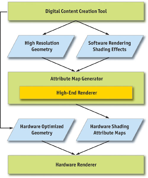
Figure 35-1 The Content Pipeline for Hardware Rendering
The tools use high-quality geometry and shading effects and compile the necessary attributes to apply onto the low-resolution version of the object. The result is that the final hardware rendering looks as close as possible to the high-quality content. By relying on a software-renderer solution, the tools can use all the features of the software renderer and then bake the result onto the final attribute maps. The rest of the chapter breaks down the process in detail.
35.3 Components of Hardware Rendering
We now have a good overview of the content pipeline for hardware rendering. In this section, we go into more detail about the specifications of the different components used in hardware shading effects. The components fall into two categories: geometric data and attribute maps.
35.3.1 Geometric Data
Geometric data is composed of the polygon mesh structure and its vertex attributes. This data is used by the hardware rasterizer to generate the pixels to be displayed. In the hardware-rendering pipeline, vertex data is processed by the vertex shader; each triangle is rasterized into fragments; and then the fragments are fed to the pixel shader, which displays them.
The mesh structure consists of triangles that are combined and sent through the hardware graphics pipeline. Users of the DCC tool generate the polygon meshes, and then the DCC converts the polygons into triangles and, optionally, creates triangle strips.
The u-v texture coordinates are important attributes of the vertex; they contain mapping information about how to sample the texture image over the surface. They also are used in several algorithms that generate tangents. Later we show how tangents are generated from the u-v texture coordinates.
Normals, tangents, and binormals are essential if the normal map is expressed in tangent space. The normals, tangents, and binormals define the basis of each vertex. Most current authoring tools support only normal editing. Later we show how to generate tangents and binormals using the surface normals and u-v coordinates.
35.3.2 Attribute Maps
Attribute maps are essentially texture maps sampled by the hardware pipeline rasterizer. Texture maps have a greater density than geometry used to create details on the surface of an object without increasing the geometric density. For example, we use texture maps to add color details to a polygon mesh.
Normal maps store normals at each texel. Each normal component (x, y, and z) is encoded in the pixel components of the texture (red, green, and blue). Because normals are of unit length, each component has a range of –1 to 1. Red, green, and blue have the range 0 to 1. Normals are encoded with an offset of 0.5 per component and a scaling of 0.5 per component. Normal maps can be optionally expressed in model space or in tangent space, as shown in Figures 35-2 and 35-3, respectively.
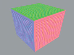
Figure 35-2 A Normal Map in Model Space
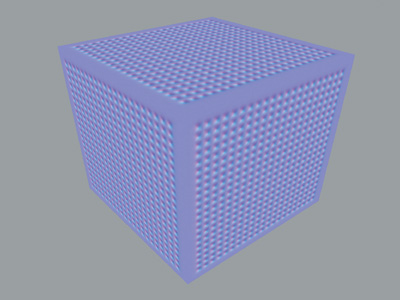
Figure 35-3 A Normal Map in Tangent Space
Normal maps in model space generally require less computation at runtime than normal maps in tangent space. However, each map is unique to the object and cannot be shared or reused on another object. Normal maps in tangent space require more vertex operations, but on the other hand, they can be tiled and reused on other objects.
Diffuse maps, as shown in Figure 35-4, are used as standard color texture maps. They are encoded as regular red, green, blue, and alpha components and represent the color at the surface of the object.
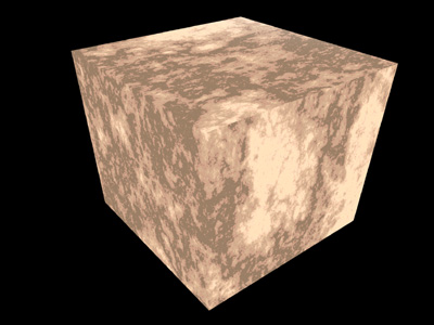
Figure 35-4 A Diffuse Map for a Surface
Reflection maps are also used as standard color texture maps. They are also encoded as regular red, green, blue, and alpha components and represent the color of the environment that is reflected by the object.
Every day new techniques for achieving advanced real-time shading effects are being explored and discovered. Other types of maps are used in hardware pixel shaders to achieve these effects:
- Procedural textures (such as noise, marble, and wood)
- Environment-based lighting
- Nonphotorealistic rendering
The technique described in this chapter for generating attribute maps can be extended and applied to these shading effects.
35.4 Generating the Components
Now that we have the specifications for the components required by the hardware renderer, we need to generate them. The artist generates some components; automated tools create others.
Ideally, the component generation step is open and flexible enough to cover the range of algorithms people use when creating vertex attributes and attribute maps. Automating the process as much as possible without sacrificing flexibility is the goal. Tangent creation often demands the most flexibility, in specifying how tangents are formed.
Normal maps are generated in the reference frame that is the most suitable for the application. However, "normal maps in tangent space" is the most popular technique, because it allows reuse of the normal map on other objects. The maps should be generated from an object with a much higher vertex density and applied to an object with a lower density. This technique allows artists to freely model highly detailed objects and bake the details of these objects onto a normal map that applies to the low-resolution model.
The technique that generates the map consists of these steps:
- Compute the normal at the surface of the high-resolution objects in model space, using the texture coordinate parameterization of the low-resolution object.
- Apply that normal map on the low-resolution object.
- Compute the tangents of the low-resolution object.
- Use the normal map in model space, plus the tangents of the low-resolution object, to compute the normal map in tangent space.
The workflow allows artists to bake arbitrary numbers of high-resolution objects, which contain arbitrary shading effects, into simple texture maps.
35.4.1 Creating the Geometry
On the geometry side, the artist creates the object with the DCC tool. However, some vertex attributes are very difficult to build by hand, so the artist usually uses a set of helper tools to create them.
35.4.2 Rendering to Textures and Vertices
To generate attribute maps, we need a tool that can render the software renderer's shading effects into texture maps using the parameterization of the target object. The same effects are also to be baked into vertex attributes.
Rendering to a texture uses an existing texture coordinate parameterization, coupled with a target texture map. For each texel of the texture, the algorithm finds the coordinates at the surface of the object. The software renderer fires a ray and sample attributes at the coordinates. By rendering to vertices, we sample these attributes at each vertex position, instead of at each texel position.
Rendering to a texture and to vertices generates only surface color attributes, so we need to find a way to render custom attributes, such as tangents and normals. The solution is to create a custom software shader that renders the surface tangents and normals into surface colors. Because hardware-programmable shading ultimately works with four-component registers, any custom attribute can be encoded as an RGBA value, either in vertex colors or in texture maps.
Figure 35-5 is an example of an object rendered with normals set into surface colors.
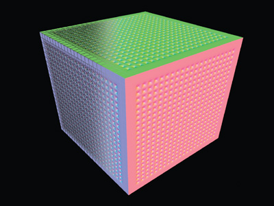
Figure 35-5 Object Normals Rendered by mental ray
We can create u-v coordinates by using a texture coordinate editor. There are also solutions that automatically unfold geometry and create a texture coordinate set that is good enough to use in the hardware pipeline.
These are the main criteria for the u-v coordinates:
- The u-v coordinates should have a good general u and v flow (good flow is characterized by minimizing any discontinuities between successive u or v values). This is critical for tools that generate tangents based on u-v coordinates. Most tangent-generation algorithms use the u and v flows of a given texture coordinate parameterization to orient the tangents at the surface of the objects.
- The u-v coordinate sets should have minimal islands, which are groups of connected triangles in u-v space; islands introduce texture-map discontinuity. These discontinuities can cause problems when the algorithm samples texels on edges that border discontinuities. This problem can be circumvented by spilling or averaging texel values, but in general, we recommend avoiding discontinuities.
Creating normals is usually part of the object modeling process. However, tangents and binormals are easily derived from u-v coordinates and the normal vectors. In our test case, we compute the binormal vector inside the vertex program by using the normal and tangent provided by the application. Tangents have to be accessible to users of the DCC tools because they may want to override the computation. We accomplish this by storing the tangents in the vertex color attributes, because the vertex color is not used in the bump-mapping test case.
The resulting vertex format to be passed to the vertex program is shown in Listing 35-1.
The binormal is computed using a cross product between the normal and the tangents.
Example 35-1.
struct app2vertex
{
  float4 position : POSITION;
  float4 normal : NORMAL;
  float4 tangent : COLOR0;
  float4 uv0 : TEXCOORD0;
  float4 uv1 : TEXCOORD1;
  float4 uv2 : TEXCOORD2;
  float4 uv3 : TEXCOORD3;
};
To compute the tangents in our test case, we use a custom mental ray shader that temporarily overrides the current object's shading and displays the tangents as vertex colors, as shown in Figure 35-6. Rendering to vertices does its magic to evaluate the mental ray shader and puts the results in vertex colors.
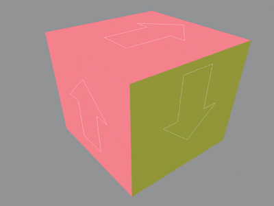
Figure 35-6 Tangents Rendered by mental ray and Set As Vertex Colors
The tangents could also be recomputed using a plug-in or a script that writes the tangent's results into the color property of the vertex.
The process for creating the texture maps required by the hardware version of the bump-map effect should be as automated as possible. The goal is to bake the complex geometry details and shading effects into the final low-resolution object. The high- and low-resolution models need not have any correlation in their u-v mapping or topology.
Generating normal maps is done in two passes. The first pass computes the normals at the surface of the high-resolution objects in model space by using the texture coordinate parameterization of the low-resolution object.
The technique we use in our test case for the first pass is as follows:
- The high-resolution objects are temporarily shaded, using a mental ray shader that renders normals as colors.
- The low-resolution object is rendered completely transparent, so its own geometry is not taken into account when rendering the details of the high-resolution objects.
- Rendering to a texture is invoked, and the high-resolution objects' details are rendered into the normal map in model space, using the low-resolution object's texture coordinate parameterization.
The geometric details of the high-resolution objects are rendered into the normal map. The cool thing is that geometric operations performed by the software renderer, such as displacement maps and geometry shaders, are taken into account. The possibility exists to "bake" procedural geometries, such as hair or particles, with this method.
The second pass uses the previously computed tangents on the low-resolution object, plus the normal map in model space, to create the normal map in tangent space.
The technique we use for the second pass is as follows:
- Make all objects, except low-resolution objects, temporarily invisible.
- On the surface of the low-resolution object, sample the normal map in model space.
- On the surface of the low-resolution object, sample the tangent by using the vertex color property.
- Using the normal and the tangent, compute the binormal to create the new referential of the sampled normal.
- Transform the sampled normal from model space to tangent space.
Generating the diffuse map is similar. In our case, an issue arises when we compute this map. Because the software renderer might execute a network of arbitrary material shaders, it is impossible to extract the different terms of the lighting equation and return the diffuse color without any lighting on it. But we can trick the renderer by providing even lighting across the surface of the objects. This trick allows the diffuse color to show up evenly, regardless of the light setup of the scene or the surface normal.
The following steps are performed to do this:
- Ambient and specular contributions are temporarily disabled on high-resolution objects. This ensures that we get a pure diffuse map.
- Lights in the scenes are temporarily disabled, and a light rig is put in place to evenly light the high-resolution objects.
- The low-resolution object is rendered completely transparent, so that its own geometry is not taken into account when rendering the details of the high-resolution objects.
- Rendering to a texture is invoked. The high-resolution objects' details are rendered into the normal map in model space, using the low-resolution object texture coordinate parameterization.
Even though our light rig setup allows us to sample the diffuse color without too much of the lighting contribution, we still get some lighting artifacts. These artifacts can be corrected using color-correction tools.
During rendering of the diffuse map pass, the shading effects that affect the diffuse color of the objects are taken into account. Artists can use procedural effects such as marble, wood, or noise textures, which are automatically baked into the surface map.
When the environment is static, we can use environment maps to simulate reflective materials. In this case, we can effectively take advantage of the high-end rendering software to generate high-quality environment maps that can even take advanced rendering effects, such as global illumination and final gathering, into account. The two most common environment maps are cubic maps and spherical maps.
For cubic maps, the rendering must be set up to fit on the bounding cube of the object and render the environment on that cube. For each face of the cube, we render the reflected image from the point of view of the reflective object. The maps generated are then used in a hardware reflection-map shader in the graphics pipeline.
For spherical maps, the camera field of view must be set up to render a hemisphere covering the part of the object that faces the viewpoint, which is then used in the hardware graphics pipeline as a spherical map for an environment shader.
This method bakes the entire advanced rendering functionally such as global illumination models and caustics using software renderers, into the resulting texture map.
35.5 Test Case and Results
To illustrate the technique documented in this chapter, we present a real-life test case and then comment on the results.
The high-resolution model we are using for the test case has 440 distinct polygon meshes and a little over 260,000 triangles. See Figures 35-7 and 35-8. The model has different types of material attached to each section of the character. The armor plates are made of a reflective, Phong-type material; the fabric on the arms is made of a nonreflective, Lambert-type material.
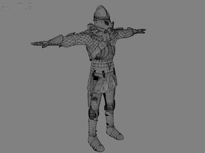
Figure 35-7 Wireframe View of the High-Resolution Model
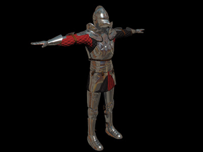
Figure 35-8 Final Rendering of the High-Resolution Model
The low-resolution model is composed of a single mesh and just under 4,000 triangles, as shown in Figure 35-9. Two types of real-time shaders will be attached to this model: (1) the real-time equivalent of a reflective bump map, which will be used for the armor; and (2) a simple nonspecular bump map, which will be used for the fabric on the arms.
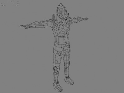
Figure 35-9 Wireframe View of the Low-Resolution Model
The high-resolution and low-resolution models have very different topologies. The high-resolution model itself has no texture coordinates, and it does not result from texture maps. All the details on the high-resolution model have been modeled as polygonal meshes. On the other hand, the low-resolution model relies entirely on texture maps to get to the result. In this case, we use two different maps: a normal map in tangent space and a diffuse map for the illumination color. The final real-time shading takes these maps as input and produces the final image, shown in Figure 35-10.
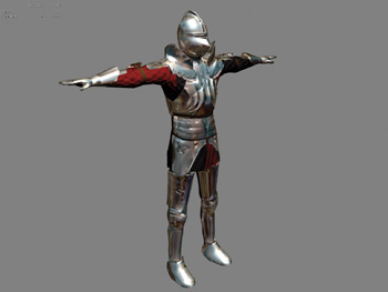
Figure 35-10 Real-Time Shading View of the Low-Resolution Model
Notice that small details on the armor, as well as the cloth quilting, actually do not exist as geometry. The GPU surface FX plug-in bakes these details into the normal maps used for the bump-map real-time effect from the high-resolution model. The same normal map is also used for doing reflection bump mapping, so the surface details appear to be distorting the reflection map.
Looking closely at the generated maps, we can see that the intermediate normal map in object space, shown in Figure 35-11, contains all the surface details of the high-resolution model. The surface of the high-resolution model is projected into the u-v space of the low-resolution model.
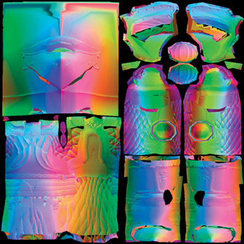
Figure 35-11 The Generated Normal Map in Object Space
The normal map in tangent space, shown in Figure 35-12, is derived from the normal map in object space and the tangents of the low-resolution model.
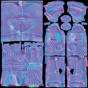
Figure 35-12 The Generated Normal Map in Tangent Space
Figure 35-13 shows the surface map that is used as the color component of the real-time effect. We can see that we have obtained good results in extracting the color from the original model as seen in Figure 35-8.
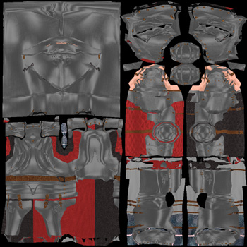
Figure 35-13 The Generated Approximate Diffuse Map
Figure 35-14 compares the software-rendered and hardware-rendered models. The result is very close to the original. However, several conditions are required for the system to generate good attribute maps. The first requirement is that the u-v space used by the low-resolution model must be adequate: it should be nonoverlapping and have minimal discontinuities. The second requirement is that the shape of the high-resolution model must resemble that of the low-resolution model. The shapes do not need a topological correlation, but the forms of both models should be similar. This requirement allows the generation of attribute maps to minimize errors when projecting the attributes of the high-resolution model onto the low-resolution model. In this test case, the artist manually edited the u-v coordinates to maximize the usage of the texture map on the surface of the model. In terms of shape delta, we found that the maximum projected distance from the high-resolution model and the low-resolution model should be relatively small.
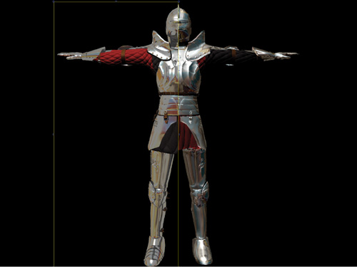
Figure 35-14 Comparing Renderers
35.6 Conclusion
High-end software rendering tools offer a robust and flexible pipeline for generating simple attribute maps such as diffuse and normal maps. The workflow we've described demonstrates how an artist's creativity can be enhanced by using an arbitrary set of high-resolution models with an arbitrary set of shader networks to generate attribute data used in the hardware-rendering pipeline and how the artist can easily iterate on the results achieved in the process.
The tools for baking down information from high-resolution models and complex shaders to usable hardware-rendering components need to be automated, keeping technical details away from the artist. Finally, if the tool set is flexible, it can be adapted to generate other types of attribute maps and to work with different hardware-rendering techniques.
The technique does need some improvements. The generation of the surface map (shown in Figure 35-13) still exhibits some shading artifacts, which require correcting with image-editing software. In the future, we will consider using a different technique to get rid of these shading artifacts. Also, rendering speed will almost always be an issue, simply because it is the bottleneck of the iterative process.
35.7 References
AVID Corporation. "Leveraging the Power of the GPU with SOFTIMAGE XSI." Available online at http://www.softimage.com
AVID Corporation. XSI User Manual.
Driemeyer, Thomas, ed. 2001. Rendering with Mental Ray , 2nd ed. Springer.
Driemeyer, Thomas, and Rolf Herken, eds. 2003. Programming Mental Ray, 2nd ed. Springer.
Fernando, Randima, and Mark J. Kilgard. 2003. The Cg Tutorial. Addison-Wesley.
Kilgard, M. J. 2000. "A Practical and Robust Bump-Mapping Technique for Today's GPUs." Available online at http://developer.nvidia.com
Microsoft Corporation. DirectX 8.0 Programmer's Reference. Available online at http://msdn.microsoft.com/directx
NVIDIA Corporation. 2002. Cg Toolkit User's Manual: A Developer's Guide to Programmable Graphics. Available online at http://developer.nvidia.com
Copyright
Many of the designations used by manufacturers and sellers to distinguish their products are claimed as trademarks. Where those designations appear in this book, and Addison-Wesley was aware of a trademark claim, the designations have been printed with initial capital letters or in all capitals.
The authors and publisher have taken care in the preparation of this book, but make no expressed or implied warranty of any kind and assume no responsibility for errors or omissions. No liability is assumed for incidental or consequential damages in connection with or arising out of the use of the information or programs contained herein.
The publisher offers discounts on this book when ordered in quantity for bulk purchases and special sales. For more information, please contact:
U.S. Corporate and Government Sales
(800) 382-3419
corpsales@pearsontechgroup.com
For sales outside of the U.S., please contact:
International Sales
international@pearsoned.com
Visit Addison-Wesley on the Web: www.awprofessional.com
Library of Congress Control Number: 2004100582
GeForce™ and NVIDIA Quadro® are trademarks or registered trademarks of NVIDIA Corporation.
RenderMan® is a registered trademark of Pixar Animation Studios.
"Shadow Map Antialiasing" © 2003 NVIDIA Corporation and Pixar Animation Studios.
"Cinematic Lighting" © 2003 Pixar Animation Studios.
Dawn images © 2002 NVIDIA Corporation. Vulcan images © 2003 NVIDIA Corporation.
Copyright © 2004 by NVIDIA Corporation.
All rights reserved. No part of this publication may be reproduced, stored in a retrieval system, or transmitted, in any form, or by any means, electronic, mechanical, photocopying, recording, or otherwise, without the prior consent of the publisher. Printed in the United States of America. Published simultaneously in Canada.
For information on obtaining permission for use of material from this work, please submit a written request to:
Pearson Education, Inc.
Rights and Contracts Department
One Lake Street
Upper Saddle River, NJ 07458
Text printed on recycled and acid-free paper.
5 6 7 8 9 10 QWT 09 08 07
5th Printing September 2007
- Contributors
- Copyright
- Foreword
- Part I: Natural Effects
-
- Chapter 1. Effective Water Simulation from Physical Models
- Chapter 2. Rendering Water Caustics
- Chapter 3. Skin in the "Dawn" Demo
- Chapter 4. Animation in the "Dawn" Demo
- Chapter 5. Implementing Improved Perlin Noise
- Chapter 6. Fire in the "Vulcan" Demo
- Chapter 7. Rendering Countless Blades of Waving Grass
- Chapter 8. Simulating Diffraction
- Part II: Lighting and Shadows
-
- Chapter 9. Efficient Shadow Volume Rendering
- Chapter 10. Cinematic Lighting
- Chapter 11. Shadow Map Antialiasing
- Chapter 12. Omnidirectional Shadow Mapping
- Chapter 13. Generating Soft Shadows Using Occlusion Interval Maps
- Chapter 14. Perspective Shadow Maps: Care and Feeding
- Chapter 15. Managing Visibility for Per-Pixel Lighting
- Part III: Materials
- Part IV: Image Processing
- Part V: Performance and Practicalities
-
- Chapter 28. Graphics Pipeline Performance
- Chapter 29. Efficient Occlusion Culling
- Chapter 30. The Design of FX Composer
- Chapter 31. Using FX Composer
- Chapter 32. An Introduction to Shader Interfaces
- Chapter 33. Converting Production RenderMan Shaders to Real-Time
- Chapter 34. Integrating Hardware Shading into Cinema 4D
- Chapter 35. Leveraging High-Quality Software Rendering Effects in Real-Time Applications
- Chapter 36. Integrating Shaders into Applications
- Part VI: Beyond Triangles
- Preface