
GPU Gems
GPU Gems is now available, right here, online. You can purchase a beautifully printed version of this book, and others in the series, at a 30% discount courtesy of InformIT and Addison-Wesley.
The CD content, including demos and content, is available on the web and for download.
Chapter 27. A Framework for Image Processing
Frank Jargstorff
NVIDIA
In this chapter, we introduce a C++ framework for image processing on the GPU. Using this framework, a programmer can easily define image filters and link filters to form filter graphs. Most of the classes in the framework act simply as handles to structures living on the graphics board, so that the actual processing of the image is almost completely performed by the GPU. The framework is based on the OpenGL API and uses the Cg programming language to implement image-processing algorithms. However, the ideas represented in this chapter apply similarly to Microsoft's DirectX API and the HLSL programming language. Our hope is that the framework will be useful to readers who are designing similar image-processing systems, either as a working foundation or as an analysis of the issues that must be resolved along the way.
27.1 Introduction
The framework we present is valuable for two reasons. First, there is the increasingly flexible programming paradigm for vertex and fragment shaders supported by recent GPUs such as the GeForce FX family. Second, today's GPUs are so powerful that they surpass the CPU's performance in many signal-processing-like applications.
Organizing image filters using filter graphs is especially practical for video processing, where a long sequence of images is processed using the same configuration of filters (for example, Microsoft's DirectShow is a filter-graph-based, real-time video-processing library). See Figure 27-1. Filter graphs are also useful in batch-processing scenarios, such as compositing movie-quality frames or processing large sets of images for Web publications (for example, Apple's Shake compositor or Adobe's ImageReady).
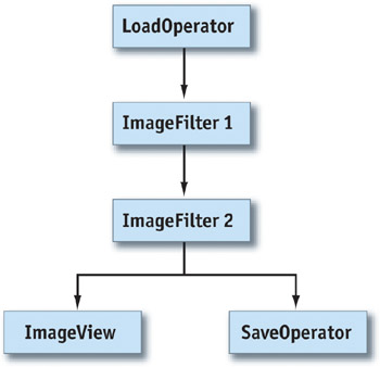
Figure 27-1 A Filter Graph
GPUs are programmed through traditional 3D APIs such as Direct3D and OpenGL. These APIs are fairly low level and were originally designed to implement 3D applications. Implementing GPU image processing directly in these APIs would be an awkward task. A framework acting as an isolation layer and specifically designed for image processing would drastically simplify the implementation of image processing on the GPU. To be simple to program, the framework should encapsulate all recurring tasks and should strive to shield the programmer from the underlying graphics API as much as possible. In the following sections, we describe a basic version of such a framework. The framework functions as an example and tries to address the most important design and implementation aspects. It does not address, however, many of the more complicated schemes necessary in an industrial-strength library, such as dividing images into tiles to process arbitrarily large images.
27.2 Framework Design
Filter networks deal with two kinds of objects:
- Data objects that flow through the network. In our case, the data flowing are images.
- Operators that act on the data. Operators come in different flavors. Some operators produce output images
without absorbing input images (for example, an operator that loads an image from disk). These operators act
as sources in the network, so they are called source operators. Other operators consume an input
image without producing an output image (for example, operators that display an image on the screen). Because
these operators act as data sinks, we refer to them as sink operators. See Figure 27-2.
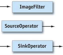
Figure 27-2 A , a , and an
For a C++ implementation, this poses two problems. For one, it is considered good design for an object that creates objects to be responsible for also deleting those objects (Meyers 1997). Because the operators creating and deleting images are usually not the same, we need some kind of automatic memory management for the Image class.
Images are fairly simple data structures that don't contain references, especially not to themselves. Thus, simple reference counting suffices as memory-management strategy.
A second issue is how the pipeline should be updated. That is, what is the mechanism that makes data percolate through the graph? The two options are to push data down the graph or pull data from the result nodes, which in turn pull the necessary data from their inputs. Because of the common use of a model-view-controller pattern (Gamma et al. 1995) for applications, we decided to implement updating by pulling.
27.2.1 Operators and Filters
The basic operators described in the previous section map directly to abstract base classes in the framework's design.
The SourceOperator base class consists of two purely virtual functions:
virtual bool dirty() = 0;
virtual Image image() = 0;
The image() method returns the operator's output image. The dirty method determines if the most recently returned image is still valid.
The SinkOperator base class contains only a single virtual function and a protected reference to a SourceOperator.
virtual void setSourceOperator(SourceOperator *pSourceOperator);

protected:

SourceOperator *_pSourceOperator;
The sink operator retrieves its input images from the source operator pointed to by _pSourceOperator. The setSourceOperator() method sets this reference.
The ImageFilter class is derived from both SourceOperator and SinkOperator, as shown in Figure 27-3.
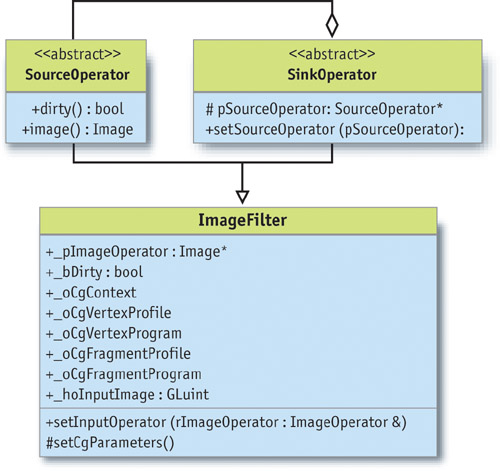
Figure 27-3 The Class Diagram
ImageFilter overloads both the image() and the dirty() methods with default implementations for all filters derived from it.
- The image() method retrieves the input image from the input operator and draws a rectangle exactly covering the entire output image. The drawing code for the rectangle sets up Cg vertex and fragment programs and uses the input operator's image as a texture. The fragment program determines how the texture is rendered to the output image. Thus, different image filters can be implemented by simply using different Cg fragment programs.
- The dirty() method recursively queries the dirty() methods of all operators upstream. If it finds that its image filter depends on a dirty operator's output, it will return true. An operator becomes dirty when any of its parameters is changed. Note: It is the responsibility of the implementer of an operator or filter to make sure that the dirty flag is set correctly.
The image() method implements everything necessary to set up and execute fragment and vertex programs. It uses a ShaderManager class to retrieve shared Cg resources. Most of the necessary and tedious Cg plumbing is encapsulated in the image method. All the implementer of a new filter class has to do is set up the actual fragment shader for his or her filter in the class's constructor.
27.2.2 Image Data
The Image class functions as a container for our image data. Therefore, it must support two basic functions: retrieving the image data and drawing new image data into the image. Because the Image class is a mere handle to the actual image residing on the graphics board, support for these functions will be high level (as opposed to low-level accesses such as setting and retrieving color values of single pixels).
This high-level interface to the image data consists simply of the following three methods:
GLuint textureID() const;
void renderBegin();
void renderEnd();
These methods allow the programmer to retrieve an OpenGL texture handle pointing to a texture containing the image data.
The render methods make the image the current OpenGL render context, so that any OpenGL draw commands issued between these two commands will draw directly into the image. Using several OpenGL extensions, it is possible to implement this interface so that the image data never gets copied around when the image is drawn to and used as a texture repeatedly, nor does it ever leave the graphics card's memory.
Beyond this, the Image class has the usual methods for querying image size and resizing the image:
int width() const;
int height() const;
void setSize(int nWidth, int nHeight);
We found in the beginning of this section that the Image class must implement automatic memory management via reference counting. In fact, the Image class is a proxy (Gamma et al. 1995) for a class called Buffer, which implements the actual functionality. See Figure 27-4. Buffer objects may be referenced only through Image objects. Each Buffer has a reference counter. The Image objects' constructor, destructor, copy constructor, and assignment operator all manipulate the reference count of the Buffer objects they point to. When the last Image referencing a Buffer is destructed, the Buffer object's reference count drops to zero, indicating that the Buffer should be destroyed also.
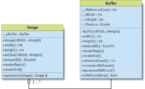
Figure 27-4 and Class Diagrams
27.2.3 Missing Pieces
We now have our data type and a handful of abstract classes to describe filter graphs. But to implement a real app, we need concrete means for image input and output. A simple application would load an image from disk, maybe apply a filter, and display the results on the screen. To do that, we need an operator to load images from disk and a display operator that renders an image to the screen.
The LoadOperator is obviously a data source and thus derived from the SourceOperator class. The load operator takes two parameters: a file name (including the path) and a file-type identifier. The operator reads the data from the file and creates an Image instance from it. The operator returns this image on every invocation of its image() method. The operator reloads a new image from the disk only when the file name or type is changed. See Figure 27-5.
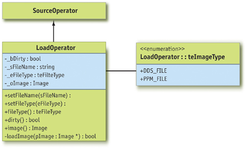
Figure 27-5 The Class Diagram
The ImageView class displays the processed images. The class is also responsible for allowing the user to resize the image (that is, zooming in and out) and move it around in the viewport (panning). Because the view only consumes processed images but doesn't produce any output for the pipeline, it is derived from the SinkOperator class.
The methods supporting this class are the following:
int imagePositionX() const;
int imagePositionY() const;
void setImagePosition(int nX, int nY);
float zoomFactor() const;
void setZoomFactor(float nZoomFactor);
These setters and getters for position and zoom factor are self-explanatory.
More interesting are the following two methods:
void center();
void changeZoomFactor(float nPercent);
The center() method centers the current image within the viewport. The changeZoomFactor(nPercent) method allows the programmer to incrementally change the zoom factor by a certain percentage. This is convenient because it allows resizing based on the current size without having to query for this information.
To correctly display the image even when the user changes the application's window size, ImageView needs to update the viewport transformation. This is achieved through a simple function that communicates any changes of the viewport size to the ImageView. The programmer of the application needs to ensure that the application informs the viewer class of any viewport changes.
void reshape(int nViewportWidth, int nViewportHeight);The mechanism to display the viewport is implemented by the following two methods:
void display();
void update();
The display() method simply renders the image currently stored in the view. Pipeline processing is not triggered by an invocation of display(). The image stored in the view is updated using the update() method. This method simply retrieves a new image from the pipeline. See Figure 27-6.
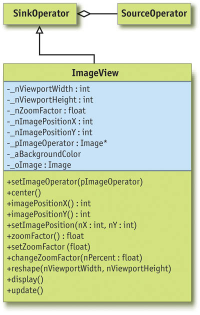
Figure 27-6 The Class Diagram
27.3 Implementation
Processing an image is fairly simple and straightforward. The filter renders a screen-aligned quad into an invisible pixel buffer. The screen-aligned quad has the input image bound as a texture. For each rendered pixel, a Cg fragment program is executed, which does the actual image processing. Because the quad is rendered using the input image as a texture, the Cg program can access the pixels in the input image though simple texture reads.
This is why implementing new image filters is so simple. It consists of writing a new Cg fragment program and some C++ code to provide the Cg program with the necessary (uniform) parameters.
All of the magic that makes sure the image isn't copied unnecessarily or moved between system memory and the graphics card is hidden in the implementation of the Image class.
The basic mechanism is to render the processed image into an invisible buffer. Once the rendering is finished and the image is ready to be processed by the next filter in the pipeline, the invisible buffer's content needs to be bound as a texture for the next rendering path.
27.3.1 The Image Class
This mechanism of rendering into an invisible buffer and using this buffer as a texture can be implemented in OpenGL using two ARB extensions: WGL_ARB_pbuffer and WGL_ARB_render_texture.
Pixel buffers (or pbuffers, created using the WGL_ARB_pbuffer extension) are such invisible buffers for OpenGL. Pixel buffers allow you to do everything that can be done with visible frame buffers. Now that we can render into an invisible buffer that resides on the graphics board, we need to find a way to use this buffer as a texture. That is exactly what the render-to-texture extension (WGL_ARB_render_texture) allows us to do.
To make things more fun, we decided to support non-power-of-two (NPOT) textures, because typical video and image resolutions are not powers of two. OpenGL supports NPOT textures through the NV_texture_rectangle extension.
Modern GPUs increasingly support floating-point data and arithmetic for color values. Floating-point numbers have great advantages over fixed-point numbers for color representation. In linear color space, the uneven distribution of floating-point numbers along the number scale matches that of the human perceptual system. Floating-point numbers are very dense around zero and have increasingly bigger steps between successive values for bigger values. Similarly, our perceptual system can distinguish small intensity variations at low intensities and gets increasingly less sensitive at high intensities. When floating-point arithmetic is used for image processing, one can also avoid clamping values to a 0-to-1 range for any intermediate steps in the process. Only for the very last step is it necessary to "normalize" the dynamic range to a fixed interval. In the easiest case, this is a simple affine mapping. But elaborate tone-mapping schemes do exist, which segment the image based on local intensities and map each segment differently. Such algorithms usually try to avoid dark areas in the image being mapped to black, and bright areas being mapped to white, respectively.
NVIDIA hardware supports two types of floating-point numbers: float (IEEE 32-bit floating point) and half. For the implementation of this framework, we decided to use the half data type for color representation. The advantages of half over float are these:
- There is a good trade-off between speed and accuracy.
- The half data type has a smaller memory footprint than the 32-bit float.
- The OpenEXR image format uses the same 16-bit floating-point numbers as NVIDIA's hardware. This allows us to load and save high-dynamic-range images in a standard format without any quality loss. (See Chapter 26 of this book, "The OpenEXR Image File Format," for a full discussion of this resource.)
To create 16-bit pbuffers, we need to use yet another OpenGL extension: WGL_ARB_pixel_format. This extension allows querying pixel formats for pixel buffers based on the tasks for which the buffer will be used (see sample code below).
So, once the WGL extensions are initialized (see DVD or NVIDIA SDK for sample code), we can write constructors and destructors for the Buffer class. See Listing 27-1.
Example 27-1. Code Setting Up OpenGL Texture Properties and Filtering
Buffer::Buffer(int nWidth, int nHeight)
    : _nReferenceCount(0), _nWidth(nWidth), _nHeight(nHeight)
{
  // Set up the texture properties
  glGenTextures(1, &_hTexture);
  glBindTexture(GL_TEXTURE_RECTANGLE_NV, _hTexture);
  glTexParameteri(GL_TEXTURE_RECTANGLE_NV, GL_TEXTURE_MAG_FILTER, GL_NEAREST);
  glTexParameteri(GL_TEXTURE_RECTANGLE_NV, GL_TEXTURE_MIN_FILTER, GL_NEAREST);
  glTexParameteri(GL_TEXTURE_RECTANGLE_NV, GL_TEXTURE_WRAP_S, GL_CLAMP_TO_EDGE);
  glTexParameteri(GL_TEXTURE_RECTANGLE_NV, GL_TEXTURE_WRAP_T, GL_CLAMP_TO_EDGE);
Listing 27-1 sets the properties for the texture to which we will bind the buffer. Notice that at the time of this writing, floating-point textures don't support any filtering except GL_NEAREST.
Because pixel buffers need their own device and render contexts, we save the current contexts now:
_hOldDC = wglGetCurrentDC();
_hOldRenderContext = wglGetCurrentContext();
Now we have to query for a suitable pixel format, as shown in Listing 27-2.
Example 27-2. Pixel-Format Selection Code
int aIntegerAttributes[15] = {WGL_DRAW_TO_PBUFFER_ARB,
                              GL_TRUE,
                              WGL_BIND_TO_TEXTURE_RECTANGLE_FLOAT_RGBA_NV,
                              GL_TRUE,
                              WGL_FLOAT_COMPONENTS_NV,
                              GL_TRUE,
                              WGL_RED_BITS_ARB,
                              16,
                              WGL_GREEN_BITS_ARB,
                              16,
                              WGL_BLUE_BITS_ARB,
                              16,
                              WGL_ALPHA_BITS_ARB,
                              16,
                              0};
float aFloatAttributes[2] = {0.0f, 0.0f};
int nPixelFormat;
unsigned int nPixelFormats;
if (0 == wglChoosePixelFormatARB(_hOldDC, aIntegerAttributes, aFloatAttributes,
                                 1, &nPixelFormat, &nPixelFormats))
{
  std::cerr < < "Error: Couldn't find a suitable pixel format." < < std::endl;
  exit(1);
}
As you can see, the call to wglChoosePixelFormatARB() requires quite a bit of preparation. The most interesting part of all this is the list of properties the pixel format must support. This property list is specified in the form of an array. The content of the array follows a simple parameter-value-pair pattern. The array has to be zero-terminated.
The wglChoosePixelFormatARB() method can return a complete array of values, but we've decided to request only a single value, specified by setting the fourth parameter to 1. The nPixelFormat variable receives our return value; the nPixelFormats variable receives the total number of pixel formats supported by the hardware that would fit our requirements. Because we need only one format to fit the bill, we discard this information.
The code in Listing 27-3 creates the actual buffer. The buffer attributes are given to the create function in an array. These attributes tell the creation method how the buffer will be used. gnFormatRGBA contains the pixel-format number. We found this number using the ARB_pixel_format extension.
Example 27-3. Pbuffer Creation Code
int aPBufferAttributes[7] = {WGL_TEXTURE_TARGET_ARB,
                             WGL_TEXTURE_RECTANGLE_NV,
                             WGL_TEXTURE_FORMAT_ARB,
                             WGL_TEXTURE_FLOAT_RGBA_NV,
                             WGL_PBUFFER_LARGEST_ARB,
                             0,
                             0};
_hPBuffer = wglCreatePbufferARB(_hOldDC, nPixelFormat, _nWidth, _nHeight,
                                aPBufferAttributes);
Now is also the time to store the pbuffer's device and render contexts. The wglShareLists() command tells OpenGL that the application and the buffer share resources (such as textures, and so on):
_hDC = wglGetPbufferDCARB(_hPBuffer);
_hRenderContext = wglCreateContext(_hDC);
wglShareLists(_hOldRenderContext, _hRenderContext);
As a last step, we bind the buffer to a texture. The buffer's default mode is to be bound to a texture. Only when we want to render to it do we unbind it:
wglMakeCurrent(_hDC, _hRenderContext);
glBindTexture(GL_TEXTURE_RECTANGLE_NV, _hTexture);
wglBindTexImageARB(_hPBuffer, WGL_FRONT_LEFT_ARB);
wglMakeCurrent(_hOldDC, _hOldRenderContext);
}
The destructor releases all the resources:
Buffer::~Buffer()
{
  wglReleasePbufferDCARB(_hPBuffer, _hDC);
  wglDestroyPbufferARB(_hPBuffer);
  wglDeleteContext(_hRenderContext);
}
With this in place, switching the buffer into render mode and back into texture mode is really simple, as shown in Listing 27-4.
Example 27-4. Switching Active Pbuffers and Binding Textures Rolled into an Easy-to-Use Begin/End Render Mechanism
void Buffer::renderBegin()
{
  glBindTexture(GL_TEXTURE_RECTANGLE_NV, _hTexture);
  wglReleaseTexImageARB(_hPBuffer, WGL_FRONT_LEFT_ARB);
  wglMakeCurrent(_hDC, _hRenderContext);
}
void Buffer::renderEnd()
{
  glBindTexture(GL_TEXTURE_RECTANGLE_NV, _hTexture);
  wglBindTexImageARB(_hPBuffer, WGL_FRONT_LEFT_ARB);
  wglMakeCurrent(_hOldDC, _hOldRenderContext);
}
27.3.2 The ImageFilter Class
As we mentioned previously, we implement the image processing by rendering a screen-aligned quad into our pbuffer. Because the actual image processing is done by a Cg program, we can implement the ImageFilter class's image() method right away, using the following trick. We define a purely virtual function, cgFragmentProgram(), which when overloaded by a derived class returns a handle to the fragment program. The image() method binds this program to render the screen-aligned quad. Concrete image filters derived from the ImageFilter base class just have to overload the method and make it return the fragment program that they want to use to process the image.
The following is a simplified version of the image() method:
Image oOutputImage;
Image oInputImage = _pSourceOperator->image();
oOutputImage.setSize(oInputImage.width(), oInputImage.height());
First, we create objects for the output image and retrieve the input image from the filter's input operator. Then we specify that the output image has the same size as the input image. (This means that, for example, a resize filter could not reuse this implementation.) See Listing 27-5. The call to renderBegin() prepares our image (that is, our pbuffer) for rendering. The code that follows sets up the rendering pipeline for simple rendering of our screen-aligned quad.
Example 27-5. Setting Up the Viewport and Projection for Processing an Image
oOutputImage.renderBegin();
{
  glViewport(0, 0, (GLsizei)oOutputImage.width(),
             (GLsizei)oOutputImage.height());
  glMatrixMode(GL_PROJECTION);
  glLoadIdentity();
  gluOrtho2D(0, oOutputImage.width(), 0, oOutputImage.height());
  glMatrixMode(GL_MODELVIEW);
  glLoadIdentity();
We then tell the Cg runtime to use a very simple vertex shader. The shader and profile are retrieved from the ShaderManager class, as shown in the following code snippet. All the vertex shader does is transform vertex coordinates according to the model-view matrix and pass the texture coordinates to the fragment shader.
cgGLEnableProfile(ShaderManager::gVertexIdentityProfile);
cgGLBindProgram(ShaderManager::gVertexIdentityShader);
Now we tell the Cg runtime which fragment program to use:
cgGLEnableProfile(cgFragmentProfile());
cgGLBindProgram(cgFragmentProgram());
Then the runtime retrieves the OpenGL texture ID from the input image and makes it the texture that the fragment program renders:
cgGLSetTextureParameter(_hoInputImage, oInputImage.textureID());
cgGLEnableTextureParameter(_hoInputImage);
What follows is another purely virtual function of the ImageFilter class. It should be used in derived classes to set additional parameters of the fragment program:
setCgParameters();Then we simply draw a screen-aligned quad, as in the following code. One note about the texture coordinates: Although texture coordinates are usually in the range [0, 1], NV_texture_rectangle textures expect their texture coordinates to be in pixels.
glBegin(GL_QUADS);
glTexCoord2f(0.0f, 0.0f);
glVertex2f(0.0f, 0.0f);
glTexCoord2f(nWidth, 0.0f);
glVertex2f(nWidth, 0.0f);
glTexCoord2f(nWidth, nHeight);
glVertex2f(nWidth, nHeight);
glTexCoord2f(0.0f, nHeight);
glVertex2f(0.0f, nHeight);
glEnd();
Finally, we conclude the rendering and return the output image:
}
oOutputImage.renderEnd();
return oOutputImage;
}
27.3.3 Implementing a Filter
Implementing a new filter derived from the general ImageFilter class involves the following tasks:
- Adding the filter's parameters. This involves defining the necessary member variables, setter methods, and getter methods. Because each parameter also needs to be passed to the Cg fragment program, it is convenient to have members representing the Cg parameters.
- Implementing the Cg fragment program. Code to load this program should be added to the filter's constructor.
- Overloading the setCgParameters() method. This method passes the parameter values stored in the filter's data members to the Cg program whenever it gets invoked.
The sample code in the following discussion comes from a simple filter implementing Gaussian blur. A Gaussian blur filter convolves the image with a filter kernel with a two-dimensional Gaussian bell curve. To avoid unbearably slow processing speeds, we limit the maximum filter-kernel size to 7x7 filters.
Filter Parameters
Blurriness is specified in terms of sigma, the Gaussian's standard deviation. sigma is the distance from the Gaussian's center to the point where the Gaussian has dropped to 50 percent of its center value. The actual filter has to be changed whenever sigma changes, so we've decided to calculate the actual filter kernel on the CPU. Therefore, we also have to store the kernel as a float array. The complete class definition for GaussFilter appears in Listing 27-6.
Example 27-6. Class Declaration for a Gaussian Filter
class GaussFilter : public ImageFilter
{
public:

  // Construction and destruction
  GaussFilter();
  virtual ~GaussFilter() { ; }
  // Set/Get sigma
  float sigma() const;
  void setSigma(float nSigma);

protected:

  virtual void setCgParameters();
  void recalculateKernel(float nSigma);

private:

  float _nSigma;
  // Standard deviation
  float _aKernel[49];
  // The filter kernel
  CGparameter _hmModelView;
  CGparameter _hKernel;
};
Deriving a new filter class obviously involves very little overhead. Except for _hmModelView, everything directly relates to the Gaussian filter. The Cg parameter for the model-view matrix is required by the vertex program to transform vertices correctly.
The Fragment Program
The Cg program for the Gauss filter simply evaluates the convolution of the filter kernel with the pixels in the original image. So, for every pixel, it multiplies all pixels covered by the filter kernel with the corresponding value in the filter kernel, and then it sums all these values to form the new pixel's color. [1] The program appears in Listing 27-7.
Example 27-7. The Fragment Program for the Gaussian Filter
void gauss(in float2 vUV
           : TEXCOORD0, out half4 vOut
           : COLOR, const uniform samplerRECT oImage,
             const uniform half aKernel[N])
{
  half4 vSum;
  int i, j, k;
  vOut = half4(0, 0, 0, 0);
  k = 0;
  for (i = -RAD; i < = RAD; i++)
    for (j = -RAD; j < = RAD; j++)
    {
      vSum += texRECT(oImage, vUV + half2(i, j)) * aKernel[k];
      k++;
    }
  vOut = vSum;
}
The constants N and RAD are used for better readability. In our case, they are defined as follows:
#define RAD 3 // Filter kernel radius #define N
49
    // Number of elements in the filter kernel
The code to set up the Cg programs and their parameters in the filter's default constructor is shown in Listing 27-8.
Setting the Cg Parameters
As previously mentioned, the code providing the Cg program with its data on invocation goes into the setCgParameters() method that needs to be overloaded by every class derived from ImageFilter.
void GaussFilter::setCgParameters()
{
  cgGLSetParameterArray1f(_hKernel, 0, 0, &(_aKernel[0]));
  cgGLSetStateMatrixParameter(_hmModelView, CG_GL_MODELVIEW_PROJECTION_MATRIX,
                              CG_GL_MATRIX_IDENTITY);
}
Example 27-8. Implementation of the GaussFilter Constructor
GaussFilter::GaussFilter() : _nSigma(1.0f)
{
  _oCgVertexProgram =
      cgCreateProgramFromFile(_oCgContext, CG_SOURCE, "VertexIdentity.cg",
                              _oCgVertexProfile, "vertexIdentity", 0);
  cgGLLoadProgram(_oCgVertexProgram);
  _oCgFragmentProgram = cgCreateProgramFromFile(
      _oCgContext, CG_SOURCE, "Gauss.cg", _oCgFragmentProfile, "gauss", 0);
  cgGLLoadProgram(_oCgFragmentProgram);
  _hmModelView = cgGetNamedParameter(_oCgVertexProgram, "mModelView");
  setSigma(_nSigma);
}
Well, that's it—we're done with our first image filter. In Figure 27-7, you can see the effect of applying this filter to an image.
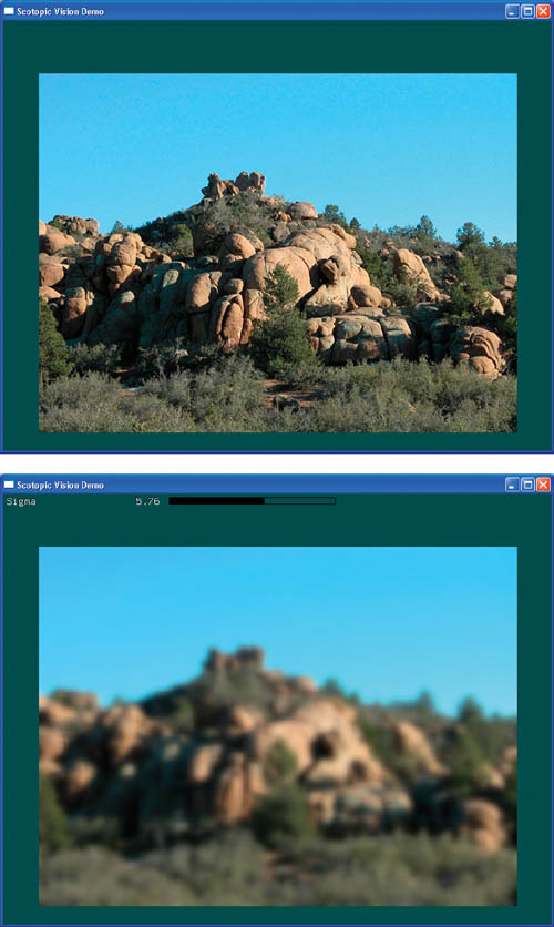
Figure 27-7 Applying a Gauss Filter
27.4 A Sample Application
To demonstrate the usefulness of our framework, we created a simple demo application. The application implements a filter that simulates night vision. When the human eye adapts to dark environments—and must rely on scotopic vision, or vision under reduced illumination—we lose most of our ability to see color. Scenes appear blurred and shaded in blue. Moviemakers exploit this behavior of the human visual system by using blue filters to shoot night scenes in bright daylight. Based on an article by William B. Thompson et al. (2002), we implemented an advanced version of this "Hollywood Night."
The post-processing algorithm proposed in Thompson et al. 2002 first converts the color image into a shades-of-blue image. Next, this image is blurred, which simulates the eye's reduced resolution in dark environments. Then an edge-sharpening filter is applied to the image. According to the article, this procedure resembles the image processing our brain applies to the blurry images our visual system delivers in darkness.
We implemented the color-conversion procedure in one operator, called NightFilter. The complete scotopic vision filter (ScotopicFilter) is a composite filter: it implements a small subpipeline within itself. See Figure 27-8.
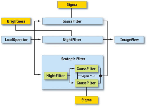
Figure 27-8 The Scotopic Filter Pipeline
The complete demo application allows processing an input image with a Gauss filter, the night-vision filter, and the scotopic filter. This is implemented by setting up the three "pipelines" and, depending on user choice, plugging the pipeline into the view operator.
In Figure 27-9, you can see the effect of the scotopic filter applied to an image.
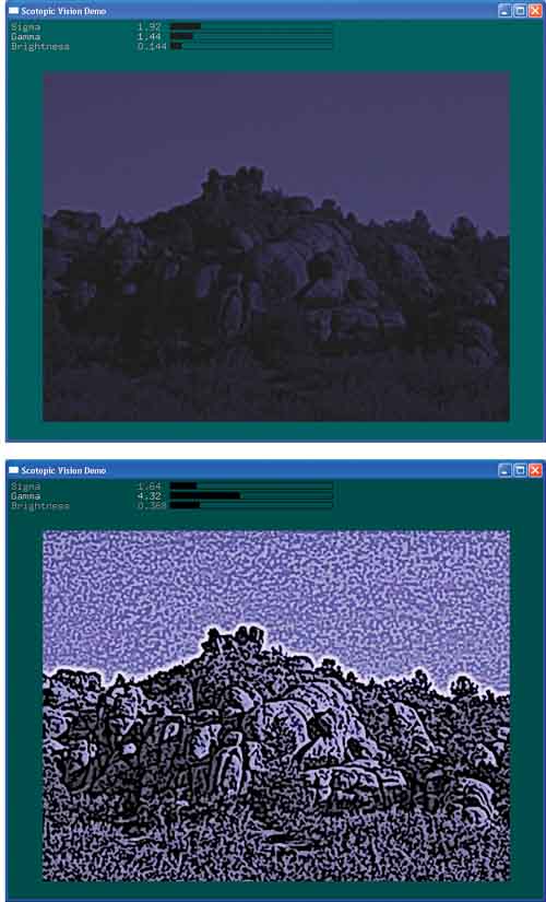
Figure 27-9 The Scotopic Filter Applied to the Photograph from .
The demo application is part of the NVIDIA Developer SDK and is available on this book's CD and Web site.
27.5 Performance and Limitations
So far in this chapter, we've avoided addressing some issues that are critical for the adoption of technologies into real-world applications: such issues include performance and hardware limitations (such as maximum texture size, limited video memory, and more). Graphics hardware continues to evolve at a pace that makes it almost impossible to discuss these issues in absolute numbers. Today's hardware limits will likely be gone tomorrow.
When designing algorithms that utilize the GPU, one should generally keep a couple of things in mind: A GPU is a highly specialized second processor. Writing code for multiprocessor systems is naturally more complex than writing ordinary code. GPUs are primarily designed to render 3D scenes. Thus, only those solutions that fit the hardware's primary purpose will benefit maximally.
Many image-processing problems map well to today's GPUs, and tenfold accelerations have been measured (Colantoni et al. 2003). Other problems that don't match very well can still profit from offloading some of the workload to the GPU. For best performance, algorithms should aim to saturate both processors—the CPU and the GPU—with workload.
Implementers of image-processing algorithms have faced hardware limitations in the past, most notably memory limitations and limited cache sizes. These problems were usually overcome by designing specific solutions. Many of these solutions have remained useful even after the original restriction was lifted (for example, virtual memory management) because of their better performance. We believe that GPU programming will develop in a similar manner.
27.6 Conclusion
The image-processing framework described in this chapter demonstrates that the processing power of modern 3D graphics hardware can be utilized for 2D image-processing tasks. The way our framework was designed and implemented shows that current (primarily 3D-oriented) graphics APIs support a clean and straightforward implementation.
The remaining limitations with respect to current hardware can be overcome with smart engineering. Future hardware and APIs will further improve performance and simplify the programming task.
27.7 References
Colantoni, Philippe, Nabil Boukala, and Jerome Da Rugna. 2003. "Fast and Accurate Color Image Processing Using 3D Graphics Cards." In Proceedings of Vision, Modeling, and Visualization 2003.
Gamma, E., R. Helm, R. Johnson, and J. Vlissides. 1995. Design Patterns: Elements of Reusable Object-Oriented Software. Addison-Wesley.
Meyers, Scott. 1997. Effective C++: 50 Specific Ways to Improve Your Programs and Designs. Addison-Wesley.
Thompson, William B., Peter Shirley, and James A. Ferwerda. 2002. "A Spatial Post-Processing Algorithm for Images of Night Scenes." Journal of Graphics Tools 7(1), pp. 1–12.
Copyright
Many of the designations used by manufacturers and sellers to distinguish their products are claimed as trademarks. Where those designations appear in this book, and Addison-Wesley was aware of a trademark claim, the designations have been printed with initial capital letters or in all capitals.
The authors and publisher have taken care in the preparation of this book, but make no expressed or implied warranty of any kind and assume no responsibility for errors or omissions. No liability is assumed for incidental or consequential damages in connection with or arising out of the use of the information or programs contained herein.
The publisher offers discounts on this book when ordered in quantity for bulk purchases and special sales. For more information, please contact:
U.S. Corporate and Government Sales
(800) 382-3419
corpsales@pearsontechgroup.com
For sales outside of the U.S., please contact:
International Sales
international@pearsoned.com
Visit Addison-Wesley on the Web: www.awprofessional.com
Library of Congress Control Number: 2004100582
GeForce™ and NVIDIA Quadro® are trademarks or registered trademarks of NVIDIA Corporation.
RenderMan® is a registered trademark of Pixar Animation Studios.
"Shadow Map Antialiasing" © 2003 NVIDIA Corporation and Pixar Animation Studios.
"Cinematic Lighting" © 2003 Pixar Animation Studios.
Dawn images © 2002 NVIDIA Corporation. Vulcan images © 2003 NVIDIA Corporation.
Copyright © 2004 by NVIDIA Corporation.
All rights reserved. No part of this publication may be reproduced, stored in a retrieval system, or transmitted, in any form, or by any means, electronic, mechanical, photocopying, recording, or otherwise, without the prior consent of the publisher. Printed in the United States of America. Published simultaneously in Canada.
For information on obtaining permission for use of material from this work, please submit a written request to:
Pearson Education, Inc.
Rights and Contracts Department
One Lake Street
Upper Saddle River, NJ 07458
Text printed on recycled and acid-free paper.
5 6 7 8 9 10 QWT 09 08 07
5th Printing September 2007
- Contributors
- Copyright
- Foreword
- Part I: Natural Effects
-
- Chapter 1. Effective Water Simulation from Physical Models
- Chapter 2. Rendering Water Caustics
- Chapter 3. Skin in the "Dawn" Demo
- Chapter 4. Animation in the "Dawn" Demo
- Chapter 5. Implementing Improved Perlin Noise
- Chapter 6. Fire in the "Vulcan" Demo
- Chapter 7. Rendering Countless Blades of Waving Grass
- Chapter 8. Simulating Diffraction
- Part II: Lighting and Shadows
-
- Chapter 9. Efficient Shadow Volume Rendering
- Chapter 10. Cinematic Lighting
- Chapter 11. Shadow Map Antialiasing
- Chapter 12. Omnidirectional Shadow Mapping
- Chapter 13. Generating Soft Shadows Using Occlusion Interval Maps
- Chapter 14. Perspective Shadow Maps: Care and Feeding
- Chapter 15. Managing Visibility for Per-Pixel Lighting
- Part III: Materials
- Part IV: Image Processing
- Part V: Performance and Practicalities
-
- Chapter 28. Graphics Pipeline Performance
- Chapter 29. Efficient Occlusion Culling
- Chapter 30. The Design of FX Composer
- Chapter 31. Using FX Composer
- Chapter 32. An Introduction to Shader Interfaces
- Chapter 33. Converting Production RenderMan Shaders to Real-Time
- Chapter 34. Integrating Hardware Shading into Cinema 4D
- Chapter 35. Leveraging High-Quality Software Rendering Effects in Real-Time Applications
- Chapter 36. Integrating Shaders into Applications
- Part VI: Beyond Triangles
- Preface