
GPU Gems
GPU Gems is now available, right here, online. You can purchase a beautifully printed version of this book, and others in the series, at a 30% discount courtesy of InformIT and Addison-Wesley.
The CD content, including demos and content, is available on the web and for download.
Chapter 41. Real-Time Stereograms
Fabio Policarpo
Paralelo Computação Ltda.
41.1 What Is a Stereogram?
A stereogram is a 2D image that encodes stereo information so that, when viewed correctly, it reveals a hidden 3D scene. It all started back in the 1960s, when Bela Julesz, who worked at (AT&T) Bell Labs researching human vision—particularly depth perception and pattern recognition—created the random-dot stereogram (RDS). Stereograms evolved from stereo photography, in which two photographs are taken from slightly different camera positions (representing the displacement between our eyes).
41.1.1 Stereo Photography
Stereo photography is very old, dating back to 1838, but some of the old stereo cameras and stereo photograph viewers, such as the one shown in Figure 41-1a, can still be found at antique shops. The idea behind stereo photography is to take two similar photographs, but from different positions displaced horizontally (like our eyes). Our eyes are separated from each other by about 65 mm, and this disparity causes slightly different images to be presented to the brain. These differences allow the perception of depth.
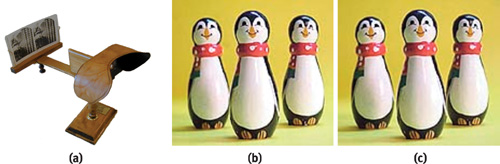
Figure 41-1 Stereo Photography
In Figure 41-1a, two images (stereo pairs) are placed side by side in front of the lenses. The lenses facilitate viewing, presenting each image to each eye, respectively. The stereo pairs must be visualized so that the left photograph is seen by the left eye, as shown in Figure 41-1b, and the right photograph by the right eye, as in Figure 41-1c. If the images are swapped (with the left image viewed by the right eye and vice versa), depth perception will be inverted.
41.1.2 Random-Dot Stereograms
To generate an RDS, we start by creating an image made of random dots, as shown in Figure 41-2a. Then we duplicate the image and modify it by selecting a region and displacing it horizontally, as in Figure 41-2b (the bigger the displacement, the deeper it looks). The gaps created by moving the regions of the image are then filled with more random-generated dots, as in Figure 41-2c, and...that's it!
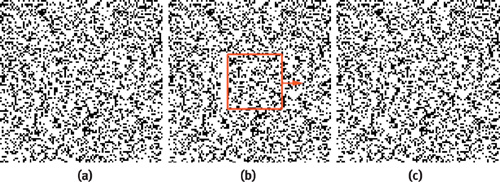
Figure 41-2 Generating an RDS
We now have two images, the original and the copied/displaced versions. Displaying each image to each eye allows the depth perception, and the hidden 3D scene is then visible.
You can view an RDS like a standard stereo photograph. To visualize an RDS (or standard stereo photographs) using only your eyes and no extra apparatus, simply look at two images, such as those in Figure 41-3, crossing your eyes before the image plane. This makes you see four images instead of two, because each image duplicates (as if you were looking at your nose).
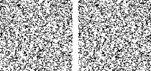
Figure 41-3 An RDS Pair Ready for Visualization
Changing the focus point moves the duplicated images in relation to each other, and when the center images merge, you'll see the 3D hidden scene. At the correct focus point, you'll see only three images: one in 3D at the center and two in 2D on the edges. See Figure 41-4 for a detailed explanation of how this works.
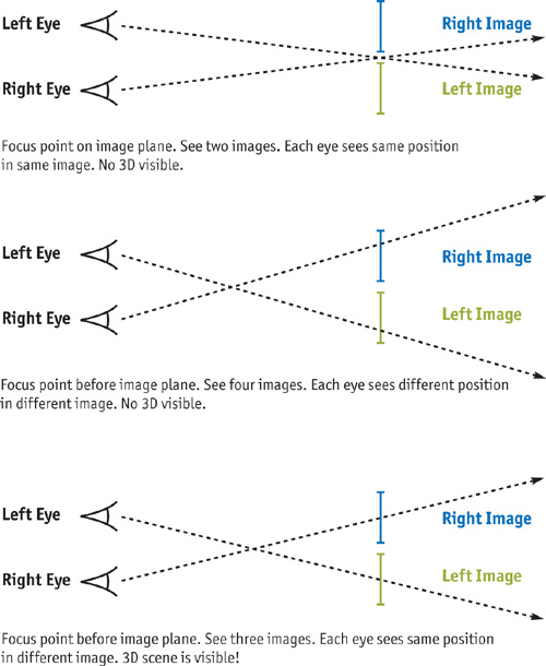
Figure 41-4 Viewing a Stereo Image Pair
41.1.3 Single-Image Stereograms
A single-image stereogram (SIS), an evolution of the standard RDS, requires only one image. The idea is that neighboring vertical slices of the image will match patterns, thus generating the depth perception. See Figure 41-5 (top). In an SIS, we slice the image into vertical strips, reducing the displacement needed when viewing. For example, if we slice the image into eight strips, we need one-eighth the displacement to view it. This allows the eye crossing point to be closer to the image plane, which is more comfortable to the viewer.
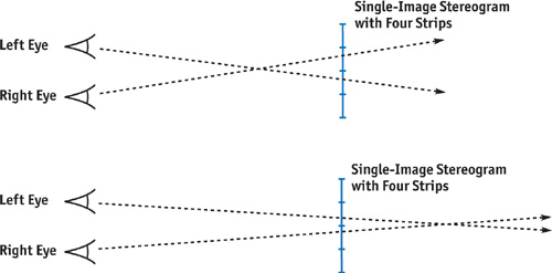
Figure 41-5 Viewing a Stereogram with Four Strips
For an RDS, the eye crossing point must be farther in front of the image plane (that is, closer to the viewer) than in an SIS, so that the displacement of the images seen is the size of the image itself. Actually, an RDS pair works just like an SIS with two strips.
With stereo photography and classic RDS images, viewers must always cross their eyes in front of the image plane. But in an SIS, because the separation between the strips is smaller than the distance between our eyes, there is an alternative, more comfortable way to view the image. Viewers can cross their eyes behind the image plane, thereby inverting their depth perception but still resulting in a 3D image. See Figure 41-5 (bottom). Most popular SIS images are generated to be viewed this way.
41.2 Creating a Single-Image Stereogram
An SIS is generated from a given depth map (that is, a grayscale image with depth information) and a tile pattern (usually a colored tile image), as in Figure 41-6.
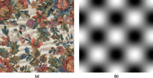
Figure 41-6 Input Images
Notice in Figure 41-7 that the tile pattern is repeated and deformed, based on the depth map. If a random-dot image is used as the tile pattern, the resulting stereogram is a single-image random-dot stereogram (SIRDS).
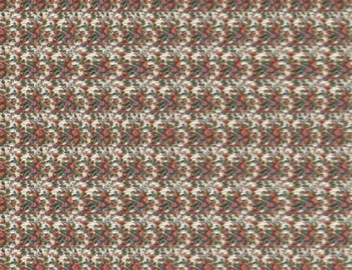
Figure 41-7 The Resulting Stereogram
41.2.1 Parameters
When creating a new SIS, we need to consider parameters: the number of strips to use; the depth factor, which can increase or decrease the depth perception (which in turn controls the amount of deformation applied to the pattern tiles); and whether to invert the depth values (white can be considered depth 0 or full-depth 1).
Here are some of the parameters:
- Number of strips (num_strips): Integer value, usually from 8 to 24
- Depth factor: Floating-point value in the range 0.0 to 1.0, with 1.0 meaning full depth
- Invert depth: Boolean value indicating whether depth values should be inverted (1 – depth)
41.2.2 Rendering
To render the SIS, we start by subdividing the depth map and the result image into vertical strips. To simplify this example, we use four strips (num_strips = 4), but for a true SIS we would use more. We then subdivide the depth map, shown in Figure 41-8, into four strips (num_strips) and divide the result map into five strips (num_strips + 1), because we need a reference strip to start with.
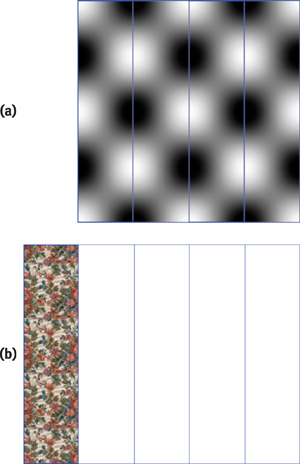
Figure 41-8 Rendering the Image
This is the pseudocode for the SIS rendering:
select_pattern_texture();
draw_strip(0);
read_strip_to_result_texture(0);
enable_fragment_program();
select_depth_texture();
select_result_texture();
for (i = 0; i < num_strips; i++)
{
  draw_strip(i + 1);
  read_strip_to_texture(i + 1);
}
disable_fragment_program();
draw_result_texture();
At the beginning of the pseudocode, we simply draw the first strip, texture-mapped with the tile pattern, as in Figure 41-8a (no fragment program is needed, just normal texture mapping). We copy the strip pixels to the result texture map (using glCopyTexSubImage2D to copy the region we just modified). We then have the result image, as shown in Figure 41-8b.
Next, we enable the fragment program and set the depth map, result map, and depth factor as parameters to it. We loop, drawing the remaining four strips from the result image. For each strip we draw, we must copy its pixels to the result texture map, because each new strip uses the previous strip's image as a reference.
When drawing the missing strips from Figure 41-8b, we will be copying the content from the previous strip and displacing pixels horizontally based on the current pixel depth. For example, if a given pixel depth is 0, we will copy the exact color of the same pixel location in the previous strip. But for other depth values, we will be getting the color from the previous strip at positions in the same scan line, but displaced proportionally to its depth.
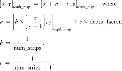
Now consider the depth map and the result map images with coordinates ranging from [0, 0] to [1, 1]. A given fragment with coordinates [x, y] uses the following computations to find the coordinates in the previous strip of the result map from where to get the color:
41.2.3 Creating Animated Single-Image Stereograms
Because SIS images can be generated in real time using the fragment program capabilities of our GPU, we can now make an animated single-image stereogram (ASIS). We will use a normal 3D scene made of triangles, and use its z-buffer as the SIS depth map—which means we'll render a 3D scene from a given viewpoint and read the z-buffer contents into the depth map texture. See Figure 41-9.
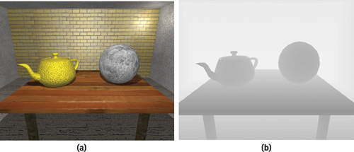
Figure 41-9 Making an Animated SIS
When we use the z-buffer from a real-time rendered scene as the source for the depth map image, we can interactively move the 3D scene (or have a predefined camera animation path) and have the stereogram update every frame to reflect the changes. This produces a real-time animated stereogram (a single frame from the animation is shown in Figure 41-10).
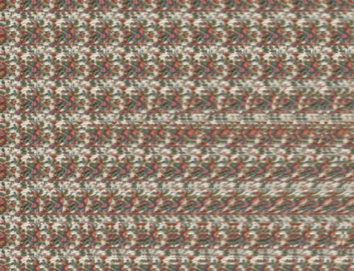
Figure 41-10 One Frame of the Animated Stereogram
It's difficult to visualize an animated stereogram, so look at it first without animation, and when you have a clear view of it, turn animation on. This is because you must keep your eye crossing point fixed at the correct distance while the image animates to be able to visualize the animated stereogram. People unfamiliar with stereograms will find it easier to search for the correct eye crossing point distance with a static image.
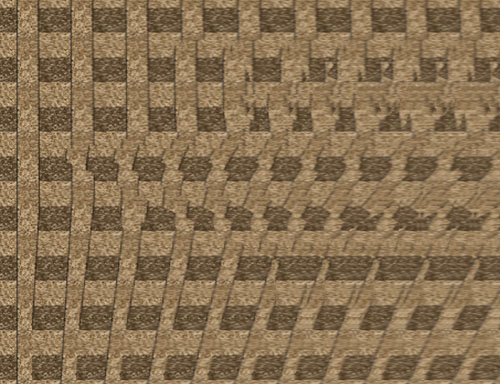
Figure 41-11 Another View with Different Color Tile
41.2.4 Fragment Program
Listing 41-1 shows the fragment program used to generate the stereograms we've discussed.
Example 41-1. Fragment Program for Generating Stereograms
struct vert2frag
{
  float4 pos : POSITION;
  float4 texcoord : TEXCOORD0;
};
struct frag2screen
{
  float4 color : COLOR;
};
frag2screen main_frag(vert2frag IN, uniform sampler2D resmap,
                      // result map
                      uniform sampler2D depthmap, // depth map
                      [ 1.0 / num_strips,
                        1.0 / (num_strips + 1) ] uniform float2 strips_info,
                      // depth factor (if negative, invert depth)
                      uniform float depth_factor)
{
  frag2screen OUT;
  // texture coordinate from result map
  float2 uv = IN.texcoord.xy;
  // transform texture coordinate into depth map space
  // (removing first strip) and get depth value
  uv.x = (IN.texcoord.x / strips_info.y - 1.0) * strips_info.x;
  float4 tex = tex2D(depthmap, uv);
  // if factor negative, invert depth
  if (depth_factor < 0.0)
    tex = 1.0 - tex.x;
  // compute displace factor
  // (depthmap_value * factor * strip_width)
  float displace = tex.x * abs(depth_factor) * strips_info.y;
  // transform texture coordinate from result map into
  // previous strip translated by the displace factor
  uv.x = IN.texcoord.x - strips_info.y + displace;
  // assign output color from result map previous strip
  OUT.color = tex2D(resmap, uv);
  return OUT;
}
41.3 Sample Application
The sample application uses OpenGL and Cg for the fragment program support. It is a simple Win32 application, and the source code is small. To run the application, start the pStereogram.exe file. To browse the source code, open the pStereogram.dsw file in Microsoft's Visual C++. The application uses the GL_ARB_fragment program extension and should execute in any environment supporting this extension. Even emulator-based fragment program support will work—slowly, but it will work.
41.3.1 Application Options
The application includes several options that let you generate new and custom-made stereograms. You can load new depth maps (Ctrl+D), new tile patterns (Ctrl+T), and new 3D geometry (Ctrl+M). Image file formats supported are JPG and TGA. The application supports 3D geometry file formats 3DS and P3D.
In the View menu, you can select options such as these:
- Texture Filtering (Ctrl+F): This option allows smooth depth ranges. If disabled, depth values will be discontinuous and you will clearly see the gaps between depth levels (like depth stairs).
- Invert Depth (Ctrl+I): This option inverts the depth values (1 – depth). It works by inverting the depth image values (white turns black and vice versa). Some people feel more comfortable viewing stereograms with the eye crossing point before the image plane, some after it (as if you were looking at something inside the monitor). If you see the 3D images entering the image plane, use this option to obtain the correct image.
- Depth Factor (<, >): This option selects the factor for multiplying the depth values. Small factors result in shallow images. High values make very deep images. The depth factor should not be higher than 1.0, or artifacts will be generated if the depth map uses all of the available range (0.0 to 1.0).
- Number of Strips (–, +): This option specifies the number of strips to use. Small values generate fewer—but larger—strips, and large values generate lots of smaller strips. This will modify how close to the image plane you have to cross your eyes to get the 3D image.
- Generate Stereogram: When this option is selected, the fragment program is activated and you'll see the stereogram. If disabled, the fragment program is deactivated and all you see is the current selected depth map.
- Depth from 3D Mesh: This option makes animated stereograms possible. When enabled, the depth map used by the program is acquired from the z-buffer of the currently selected 3D mesh object render. In this mode, you can navigate the 3D scene while viewing the resulting stereogram. Some 3D scenes might include more than one camera, and some cameras might be animated, so change cameras using the number keys: "1", "2", . . . , "9". You can move through the scene interactively by using the "S", "X", and arrow keys. You can also rotate the view by clicking and dragging with the left mouse button and pan the view with the right mouse button.
41.4 References
The SIRDS FAQ. http://www.cs.waikato.ac.nz/~singlis/sirds.html
The Magic Eye Web site. http://www.magiceye.com
Thimbleby, Harold W., Stuart Inglis, and Ian H. Witten. 1994. "Displaying 3D Images: Algorithms for Single Image Random Dot Stereograms." Journal Computer 27(10), pp. 38–48. Available online at http://archive.museophile.sbu.ac.uk/3d/pub/SIRDS-paper.pdf
Copyright
Many of the designations used by manufacturers and sellers to distinguish their products are claimed as trademarks. Where those designations appear in this book, and Addison-Wesley was aware of a trademark claim, the designations have been printed with initial capital letters or in all capitals.
The authors and publisher have taken care in the preparation of this book, but make no expressed or implied warranty of any kind and assume no responsibility for errors or omissions. No liability is assumed for incidental or consequential damages in connection with or arising out of the use of the information or programs contained herein.
The publisher offers discounts on this book when ordered in quantity for bulk purchases and special sales. For more information, please contact:
U.S. Corporate and Government Sales
(800) 382-3419
corpsales@pearsontechgroup.com
For sales outside of the U.S., please contact:
International Sales
international@pearsoned.com
Visit Addison-Wesley on the Web: www.awprofessional.com
Library of Congress Control Number: 2004100582
GeForce™ and NVIDIA Quadro® are trademarks or registered trademarks of NVIDIA Corporation.
RenderMan® is a registered trademark of Pixar Animation Studios.
"Shadow Map Antialiasing" © 2003 NVIDIA Corporation and Pixar Animation Studios.
"Cinematic Lighting" © 2003 Pixar Animation Studios.
Dawn images © 2002 NVIDIA Corporation. Vulcan images © 2003 NVIDIA Corporation.
Copyright © 2004 by NVIDIA Corporation.
All rights reserved. No part of this publication may be reproduced, stored in a retrieval system, or transmitted, in any form, or by any means, electronic, mechanical, photocopying, recording, or otherwise, without the prior consent of the publisher. Printed in the United States of America. Published simultaneously in Canada.
For information on obtaining permission for use of material from this work, please submit a written request to:
Pearson Education, Inc.
Rights and Contracts Department
One Lake Street
Upper Saddle River, NJ 07458
Text printed on recycled and acid-free paper.
5 6 7 8 9 10 QWT 09 08 07
5th Printing September 2007
- Contributors
- Copyright
- Foreword
- Part I: Natural Effects
-
- Chapter 1. Effective Water Simulation from Physical Models
- Chapter 2. Rendering Water Caustics
- Chapter 3. Skin in the "Dawn" Demo
- Chapter 4. Animation in the "Dawn" Demo
- Chapter 5. Implementing Improved Perlin Noise
- Chapter 6. Fire in the "Vulcan" Demo
- Chapter 7. Rendering Countless Blades of Waving Grass
- Chapter 8. Simulating Diffraction
- Part II: Lighting and Shadows
-
- Chapter 9. Efficient Shadow Volume Rendering
- Chapter 10. Cinematic Lighting
- Chapter 11. Shadow Map Antialiasing
- Chapter 12. Omnidirectional Shadow Mapping
- Chapter 13. Generating Soft Shadows Using Occlusion Interval Maps
- Chapter 14. Perspective Shadow Maps: Care and Feeding
- Chapter 15. Managing Visibility for Per-Pixel Lighting
- Part III: Materials
- Part IV: Image Processing
- Part V: Performance and Practicalities
-
- Chapter 28. Graphics Pipeline Performance
- Chapter 29. Efficient Occlusion Culling
- Chapter 30. The Design of FX Composer
- Chapter 31. Using FX Composer
- Chapter 32. An Introduction to Shader Interfaces
- Chapter 33. Converting Production RenderMan Shaders to Real-Time
- Chapter 34. Integrating Hardware Shading into Cinema 4D
- Chapter 35. Leveraging High-Quality Software Rendering Effects in Real-Time Applications
- Chapter 36. Integrating Shaders into Applications
- Part VI: Beyond Triangles
- Preface