
GPU Gems
GPU Gems is now available, right here, online. You can purchase a beautifully printed version of this book, and others in the series, at a 30% discount courtesy of InformIT and Addison-Wesley.
The CD content, including demos and content, is available on the web and for download.
Chapter 28. Graphics Pipeline Performance
Cem Cebenoyan
NVIDIA
28.1 Overview
Over the past few years, the hardware-accelerated rendering pipeline has rapidly increased in complexity, bringing with it increasingly intricate and potentially confusing performance characteristics. Improving performance used to mean simply reducing the CPU cycles of the inner loops in your renderer; now it has become a cycle of determining bottlenecks and systematically attacking them. This loop of identification and optimization is fundamental to tuning a heterogeneous multiprocessor system; the driving idea is that a pipeline, by definition, is only as fast as its slowest stage. Thus, while premature and unfocused optimization in a single-processor system can lead to only minimal performance gains, in a multiprocessor system such optimization very often leads to zero gains.
Working hard on graphics optimization and seeing zero performance improvement is no fun. The goal of this chapter is to keep you from doing exactly that.
28.1.1 The Pipeline
The pipeline, at the very highest level, can be broken into two parts: the CPU and the GPU. Although CPU optimization is a critical part of optimizing your application, it will not be the focus of this chapter, because much of this optimization has little to do with the graphics pipeline.
Figure 28-1 shows that within the GPU, there are a number of functional units operating in parallel, which essentially act as separate special-purpose processors, and a number of spots where a bottleneck can occur. These include vertex and index fetching, vertex shading (transform and lighting, or T&L), fragment shading, and raster operations (ROP).
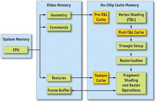
Figure 28-1 The Graphics Pipeline
28.1.2 Methodology
Optimization without proper bottleneck identification is the cause of much wasted development effort, and so we formalize the process into the following fundamental identification and optimization loop:
- Identify the bottleneck. For each stage in the pipeline, vary either its workload or its computational ability (that is, clock speed). If performance varies, you've found a bottleneck.
- Optimize. Given the bottlenecked stage, reduce its workload until performance stops improving or until you achieve your desired level of performance.
- Repeat. Do steps 1 and 2 again until the desired performance level is reached.
28.2 Locating the Bottleneck
Locating the bottleneck is half the battle in optimization, because it enables you to make intelligent decisions about focusing your actual optimization efforts. Figure 28-2 shows a flow chart depicting the series of steps required to locate the precise bottleneck in your application. Note that we start at the back end of the pipeline, with the frame-buffer operations (also called raster operations) and end at the CPU. Note also that while any single primitive (usually a triangle), by definition, has a single bottleneck, over the course of a frame the bottleneck most likely changes. Thus, modifying the workload on more than one stage in the pipeline often influences performance. For example, a low-polygon skybox is often bound by fragment shading or frame-buffer access; a skinned mesh that maps to only a few pixels on screen is often bound by CPU or vertex processing. For this reason, it frequently helps to vary workloads on an object-by-object, or material-by-material, basis.
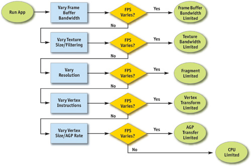
Figure 28-2 Bottleneck Flowchart
For each pipeline stage, we also mention the GPU clock to which it's tied (that is, core or memory). This information is useful in conjunction with tools such as PowerStrip (EnTech Taiwan 2003), which allows you to reduce the relevant clock speed and observe performance changes in your application.
28.2.1 Raster Operations
The very back end of the pipeline, raster operations (often called the ROP), is responsible for reading and writing depth and stencil, doing the depth and stencil comparisons, reading and writing color, and doing alpha blending and testing. As you can see, much of the ROP workload taxes the available frame-buffer bandwidth.
The best way to test if your application is frame-buffer-bandwidth bound is to vary the bit depths of the color or the depth buffers, or both. If reducing your bit depth from 32-bit to 16-bit significantly improves your performance, then you are definitely frame-buffer-bandwidth bound.
Frame-buffer bandwidth is a function of GPU memory clock, so modifying memory clocks is another technique for helping to identify this bottleneck.
28.2.2 Texture Bandwidth
Texture bandwidth is consumed any time a texture fetch request goes out to memory. Although modern GPUs have texture caches designed to minimize extraneous memory requests, they obviously still occur and consume a fair amount of memory bandwidth.
Modifying texture formats can be trickier than modifying frame-buffer formats as we did when inspecting the ROP; instead, we recommend changing the effective texture size by using a large amount of positive mipmap level-of-detail (LOD) bias. This makes texture fetches access very coarse levels of the mipmap pyramid, which effectively reduces the texture size. If this modification causes performance to improve significantly, you are bound by texture bandwidth.
Texture bandwidth is also a function of GPU memory clock.
28.2.3 Fragment Shading
Fragment shading refers to the actual cost of generating a fragment, with associated color and depth values. This is the cost of running the "pixel shader" or "fragment shader." Note that fragment shading and frame-buffer bandwidth are often lumped together under the heading fill rate, because both are a function of screen resolution. However, they are two distinct stages in the pipeline, and being able to tell the difference between the two is critical to effective optimization.
Before the advent of highly programmable fragment-processing GPUs, it was rare to be bound by fragment shading. It was often frame-buffer bandwidth that caused the inevitable correlation between screen resolution and performance. This pendulum is now starting to swing toward fragment shading, however, as the newfound flexibility enables developers to spend oodles of cycles making fancy pixels.
The first step in determining if fragment shading is the bottleneck is simply to change the resolution. Because we've already ruled out frame-buffer bandwidth by trying different frame-buffer bit depths, if adjusting resolution causes performance to change, the culprit is most likely fragment shading. A supplementary approach would be to modify the length of your fragment programs and see if this influences performance. But be careful not to add instructions that can easily be optimized away by a clever device driver.
Fragment-shading speed is a function of the GPU core clock.
28.2.4 Vertex Processing
The vertex transformation stage of the rendering pipeline is responsible for taking an input set of vertex attributes (such as model-space positions, vertex normals, texture coordinates, and so on) and producing a set of attributes suitable for clipping and rasterization (such as homogeneous clip-space position, vertex lighting results, texture coordinates, and more). Naturally, performance in this stage is a function of the work done per vertex, along with the number of vertices being processed.
With programmable transformations, determining if vertex processing is your bottleneck is a simple matter of changing the length of your vertex program. If performance changes, you are vertex-processing bound. If you're adding instructions, be careful to add ones that actually do meaningful work; otherwise, the instructions may be optimized away by the compiler or the driver. For example, no-ops that refer to constant registers (such as adding a constant register that has a value of zero) often cannot be optimized away because the driver usually doesn't know the value of a constant at program-compile time.
If you're using fixed-function transformations, it's a little trickier. Try modifying the load by changing vertex work such as specular lighting or texture-coordinate generation state.
Vertex processing speed is a function of the GPU core clock.
28.2.5 Vertex and Index Transfer
Vertices and indices are fetched by the GPU as the first step in the GPU part of the pipeline. The performance of vertex and index fetching can vary depending on where the actual vertices and indices are placed. They are usually either in system memory—which means they will be transferred to the GPU over a bus such as AGP or PCI Express—or in local frame-buffer memory. Often, on PC platforms especially, this decision is left up to the device driver instead of the application, although modern graphics APIs allow applications to provide usage hints to help the driver choose the correct memory type.
Determining if vertex or index fetching is a bottleneck in your application entails modifying the vertex format size.
Vertex and index fetching performance is a function of the AGP/PCI Express rate if the data is placed in system memory; it's a function of the memory clock if data is placed in local frame-buffer memory.
If none of these tests influences your performance significantly, you are primarily CPU bound. You may verify this fact by underclocking your CPU: if performance varies proportionally, you are CPU bound.
28.3 Optimization
Now that we have identified the bottleneck, we must optimize that particular stage to improve application performance. The following tips are categorized by offending stage.
28.3.1 Optimizing on the CPU
Many applications are CPU bound—sometimes for good reason, such as complex physics or AI, and sometimes because of poor batching or resource management. If you've found that your application is CPU bound, try the following suggestions to reduce CPU work in the rendering pipeline.
Reduce Resource Locking
Anytime you perform a synchronous operation that demands access to a GPU resource, there is the potential to massively stall the GPU pipeline, which costs both CPU and GPU cycles. CPU cycles are wasted because the CPU must sit and spin in a loop, waiting for the (very deep) GPU pipeline to idle and return the requested resource. GPU cycles are then wasted as the pipeline sits idle and has to refill.
This locking can occur anytime you
- Lock or read from a surface you were previously rendering to
- Write to a surface the GPU is reading from, such as a texture or a vertex buffer
In general, you should avoid accessing a resource the GPU is using during rendering.
Maximize Batch Size
We can also call this tip "Minimize the Number of Batches." A batch is a group of primitives rendered with a single API rendering call (for example, DrawIndexedPrimitive in DirectX 9). The size of a batch is the number of primitives it contains. As a wise man once said, "Batch, Batch, Batch!" (Wloka 2003). Every API function call to draw geometry has an associated CPU cost, so maximizing the number of triangles submitted with every draw call will minimize the CPU work done for a given number of triangles rendered.
Some tips to maximize the size of your batches:
- If using triangle strips, use degenerate triangles to stitch together disjoint strips. This will enable you to send multiple strips, provided that they share material, in a single draw call.
- Use texture pages. Batches are frequently broken when different objects use different textures. By arranging many textures into a single 2D texture and setting your texture coordinates appropriately, you can send geometry that uses multiple textures in a single draw call. Note that this technique can have issues with mipmapping and antialiasing. One technique that sidesteps many of these issues is to pack individual 2D textures into each face of a cube map.
- Use GPU shader branching to increase batch size. Modern GPUs have flexible vertex- and fragment-processing pipelines that allow for branching inside the shader. For example, if two batches are separate because one requires a four-bone skinning vertex shader and the other requires a two-bone skinning vertex shader, you could instead write a vertex shader that loops over the number of bones required, accumulating blending weights, and then breaks out of the loop when the weights sum to one. This way, the two batches could be combined into one. On architectures that don't support shader branching, similar functionality can be implemented, at the cost of shader cycles, by using a four-bone vertex shader on everything and simply zeroing out the bone weights on vertices that have fewer than four bone influences.
- Use the vertex shader constant memory as a lookup table of matrices. Often batches get broken when many small objects share all material properties but differ only in matrix state (for example, a forest of similar trees, or a particle system). In these cases, you can load n of the differing matrices into the vertex shader constant memory and store indices into the constant memory in the vertex format for each object. Then you would use this index to look up into the constant memory in the vertex shader and use the correct transformation matrix, thus rendering n objects at once.
- Defer decisions as far down in the pipeline as possible. It's faster to use the alpha channel of your texture as a gloss factor, rather than break the batch to set a pixel shader constant for glossiness. Similarly, putting shading data in your textures and vertices can allow for larger batch submissions.
28.3.2 Reducing the Cost of Vertex Transfer
Vertex transfer is rarely the bottleneck in an application, but it's certainly not impossible for it to happen. If the transfer of vertices or, less likely, indices is the bottleneck in your application, try the following:
- Use the fewest possible bytes in your vertex format. Don't use floats for everything if bytes would suffice (for colors, for example).
- Generate potentially derivable vertex attributes inside the vertex program instead of storing them inside the input vertex format. For example, there's often no need to store a tangent, binormal, and normal: given any two, the third can be derived using a simple cross product in the vertex program. This technique trades vertex-processing speed for vertex transfer rate.
- Use 16-bit indices instead of 32-bit indices. 16-bit indices are cheaper to fetch, are cheaper to move around, and take less memory.
- Access vertex data in a relatively sequential manner. Modern GPUs cache memory accesses when fetching vertices. As in any memory hierarchy, spatial locality of reference helps maximize hits in the cache, thus reducing bandwidth requirements.
28.3.3 Optimizing Vertex Processing
Vertex processing is rarely the bottleneck on modern GPUs, but it may occur, depending on your usage patterns and target hardware.
Try these suggestions if you're finding that vertex processing is the bottleneck in your application:
- Optimize for the post-T&L vertex cache. Modern GPUs have a small first-in, first-out (FIFO) cache that stores the result of the most recently transformed vertices; a hit in this cache saves all transform and lighting work, along with all work done earlier in the pipeline. To take advantage of this cache, you must use indexed primitives, and you must order your vertices to maximize locality of reference over the mesh. There are tools available—including D3DX and NVTriStrip (NVIDIA 2003)—that can help you with this task.
- Reduce the number of vertices processed. This is rarely the fundamental issue, but using a simple level-of-detail scheme, such as a set of static LODs, certainly helps reduce vertex-processing load.
- Use vertex-processing LOD. Along with using LODs for the number of vertices processed, try LODing the vertex computations themselves. For example, it is likely unnecessary to do full four-bone skinning on distant characters, and you can probably get away with cheaper approximations for the lighting. If your material is multipassed, reducing the number of passes for lower LODs in the distance will also reduce vertex-processing cost.
- Pull out per-object computations onto the CPU. Often, a calculation that changes once per object or per frame is done in the vertex shader for convenience. For example, transforming a directional light vector to eye space is sometimes done in the vertex shader, although the result of the computation changes only once per frame.
- Use the correct coordinate space. Frequently, choice of coordinate space affects the number of instructions required to compute a value in the vertex program. For example, when doing vertex lighting, if your vertex normals are stored in object space and the light vector is stored in eye space, then you will have to transform one of the two vectors in the vertex shader. If the light vector was instead transformed into object space once per object on the CPU, no per-vertex transformation would be necessary, saving GPU vertex instructions.
- Use vertex branching to "early-out" of computations. If you are looping over a number of lights in the vertex shader and doing normal, low-dynamic-range, [0..1] lighting, you can check for saturation to 1—or if you're facing away from the light—and then break out of further computations. A similar optimization can occur with skinning, where you can break when your weights sum to 1 (and therefore all subsequent weights would be 0). Note that this depends on how the GPU implements vertex branching, and it isn't guaranteed to improve performance on all architectures.
28.3.4 Speeding Up Fragment Shading
If you're using long and complex fragment shaders, it is often likely that you're fragment-shading bound. If so, try these suggestions:
- Render depth first. Rendering a depth-only (no-color) pass before rendering your primary shading passes can dramatically boost performance, especially in scenes with high depth complexity, by reducing the amount of fragment shading and frame-buffer memory access that needs to be performed. To get the full benefits of a depth-only pass, it's not sufficient to just disable color writes to the frame buffer; you should also disable all shading on fragments, even shading that affects depth as well as color (such as alpha test).
- Help early-z optimizations throw away fragment processing. Modern GPUs have silicon designed to avoid shading occluded fragments, but these optimizations rely on knowledge of the scene up to the current point; they can be improved dramatically by rendering in a roughly front-to-back order. Also, laying down depth first (see the previous tip) in a separate pass can help substantially speed up subsequent passes (where all the expensive shading is done) by effectively reducing their shaded-depth complexity to 1.
- Store complex functions in textures. Textures can be enormously useful as lookup tables, and their results are filtered for free. The canonical example here is a normalization cube map, which allows you to normalize an arbitrary vector at high precision for the cost of a single texture lookup.
- Move per-fragment work to the vertex shader. Just as per-object work in the vertex shader should be moved to the CPU instead, per-vertex computations (along with computations that can be correctly linearly interpolated in screen space) should be moved to the vertex shader. Common examples include computing vectors and transforming vectors between coordinate systems.
- Use the lowest precision necessary. APIs such as DirectX 9 allow you to specify precision hints in fragment shader code for quantities or calculations that can work with reduced precision. Many GPUs can take advantage of these hints to reduce internal precision and improve performance.
- Avoid excessive normalization. A common mistake is to get "normalization-happy": normalizing every single vector every step of the way when performing a calculation. Recognize which transformations preserve length (such as transformations by an orthonormal basis) and which computations do not depend on vector length (such as cube-map lookups).
- Consider using fragment shader level of detail. Although it offers less bang for the buck than vertex LOD (simply because objects in the distance naturally LOD themselves with respect to pixel processing, due to perspective), reducing the complexity of the shaders in the distance, and decreasing the number of passes over a surface, can lessen the fragment-processing workload.
- Disable trilinear filtering where unnecessary. Trilinear filtering, even when not consuming extra texture bandwidth, costs extra cycles to compute in the fragment shader on most modern GPU architectures. On textures where mip-level transitions are not readily discernible, turn trilinear filtering off to save fill rate.
- Use the simplest shader type possible. In both Direct3D and OpenGL, there are a number of different ways to shade fragments. For example, in Direct3D 9, you can specify fragment shading using, in order of increasing complexity and power, texture-stage states, pixel shaders version 1.x (ps.1.1 – ps.1.4), pixel shaders version 2.x., or pixel shaders version 3.0. In general, you should use the simplest shader type that allows you to create the intended effect. The simpler shader types offer a number of implicit assumptions that often allow them to be compiled to faster native pixel-processing code by the GPU driver. A nice side effect is that these shaders would then work on a broader range of hardware.
28.3.5 Reducing Texture Bandwidth
If you've found that you're memory-bandwidth bound, but mostly when fetching from textures, consider these optimizations:
- Reduce the size of your textures. Consider your target resolution and texture coordinates. Do your users ever get to see your highest mip level? If not, consider scaling back the size of your textures. This can be especially helpful if overloaded frame-buffer memory has forced texturing to occur from nonlocal memory (such as system memory, over the AGP or PCI Express bus). The NVPerfHUD tool (NVIDIA 2003) can help diagnose this problem, as it shows the amount of memory allocated by the driver in various heaps.
- Compress all color textures. All textures that are used just as decals or detail textures should be compressed, using DXT1, DXT3, or DXT5, depending on the specific texture's alpha needs. This step will reduce memory usage, reduce texture bandwidth requirements, and improve texture cache efficiency.
- Avoid expensive texture formats if not necessary. Large texture formats, such as 64-bit or 128-bit floating-point formats, obviously cost much more bandwidth to fetch from. Use these only as necessary.
- Always use mipmapping on any surface that may be minified. In addition to improving quality by reducing texture aliasing, mipmapping improves texture cache utilization by localizing texture-memory access patterns for minified textures. If you find that mipmapping on certain surfaces makes them look blurry, avoid the temptation to disable mipmapping or add a large negative LOD bias. Prefer anisotropic filtering instead and adjust the level of anisotropy per batch as appropriate.
28.3.6 Optimizing Frame-Buffer Bandwidth
The final stage in the pipeline, ROP, interfaces directly with the frame-buffer memory and is the single largest consumer of frame-buffer bandwidth. For this reason, if bandwidth is an issue in your application, it can often be traced to the ROP. Here's how to optimize for frame-buffer bandwidth:
- Render depth first. This step reduces not only fragment-shading cost (see the previous section), but also frame-buffer bandwidth cost.
- Reduce alpha blending. Note that alpha blending, with a destination-blending factor set to anything other than 0, requires both a read and a write to the frame buffer, thus potentially consuming double the bandwidth. Reserve alpha blending for only those situations that require it, and be wary of high levels of alpha-blended depth complexity.
- Turn off depth writes when possible. Writing depth is an additional consumer of bandwidth, and it should be disabled in multipass rendering (where the final depth is already in the depth buffer); when rendering alpha-blended effects, such as particles; and when rendering objects into shadow maps (in fact, for rendering into color-based shadow maps, you can turn off depth reads as well).
- Avoid extraneous color-buffer clears. If every pixel is guaranteed to be overwritten in the frame buffer by your application, then avoid clearing color, because it costs precious bandwidth. Note, however, that you should clear the depth and stencil buffers whenever you can, because many early-z optimizations rely on the deterministic contents of a cleared depth buffer.
- Render roughly front to back. In addition to the fragment-shading advantages mentioned in the previous section, there are similar benefits for frame-buffer bandwidth. Early-z hardware optimizations can discard extraneous frame-buffer reads and writes. In fact, even older hardware, which lacks these optimizations, will benefit from this step, because more fragments will fail the depth test, resulting in fewer color and depth writes to the frame buffer.
- Optimize skybox rendering. Skyboxes are often frame-buffer-bandwidth bound, but you must decide how to optimize them: (1) render them last, reading (but not writing) depth, and allow the early-z optimizations along with regular depth buffering to save bandwidth; or (2) render the skybox first, and disable all depth reads and writes. Which option will save you more bandwidth is a function of the target hardware and how much of the skybox is visible in the final frame. If a large portion of the skybox is obscured, the first technique will likely be better; otherwise, the second one may save more bandwidth.
- Use floating-point frame buffers only when necessary. These formats obviously consume much more bandwidth than smaller, integer formats. The same applies for multiple render targets.
- Use a 16-bit depth buffer when possible. Depth transactions are a huge consumer of bandwidth, so using 16-bit instead of 32-bit can be a giant win, and 16-bit is often enough for small-scale, indoor scenes that don't require stencil. A 16-bit depth buffer is also often enough for render-to-texture effects that require depth, such as dynamic cube maps.
- Use 16-bit color when possible. This advice is especially applicable to render-to-texture effects, because many of these, such as dynamic cube maps and projected-color shadow maps, work just fine in 16-bit color.
28.4 Conclusion
As power and programmability increase in modern GPUs, so does the complexity of extracting every bit of performance out of the machine. Whether your goal is to improve the performance of a slow application or to look for areas where you can improve image quality "for free," a deep understanding of the inner workings of the graphics pipeline is required. As the GPU pipeline continues to evolve, the fundamental ideas of optimization will still apply: first identify the bottleneck, by varying the load or the computational power of each unit; then systematically attack those bottlenecks, using your understanding of how each pipeline unit behaves.
28.5 References
EnTech Taiwan. 2003. Web site. http://www.entechtaiwan.com. Information on the PowerStrip package is available here.
NVIDIA. 2003. Developer Web site. http://developer.nvidia.com. On this site, you can find tools that will help you with performance tuning.
Wloka, Matthias. 2003. "Batch, Batch, Batch: What Does It Really Mean?" Presentation at Game Developers Conference 2003. Available online at http://developer.nvidia.com/docs/IO/8230/BatchBatchBatch.pdf Specific information can be found at the following Web addresses.
- D3DX: Available in the Microsoft DirectX 9 SDK. See http://msdn.microsoft.com/directx
- NVTriStrip: http://developer.nvidia.com/object/nvtristrip_library.html
- NVPerfHUD: http://developer.nvidia.com
Copyright
Many of the designations used by manufacturers and sellers to distinguish their products are claimed as trademarks. Where those designations appear in this book, and Addison-Wesley was aware of a trademark claim, the designations have been printed with initial capital letters or in all capitals.
The authors and publisher have taken care in the preparation of this book, but make no expressed or implied warranty of any kind and assume no responsibility for errors or omissions. No liability is assumed for incidental or consequential damages in connection with or arising out of the use of the information or programs contained herein.
The publisher offers discounts on this book when ordered in quantity for bulk purchases and special sales. For more information, please contact:
U.S. Corporate and Government Sales
(800) 382-3419
corpsales@pearsontechgroup.com
For sales outside of the U.S., please contact:
International Sales
international@pearsoned.com
Visit Addison-Wesley on the Web: www.awprofessional.com
Library of Congress Control Number: 2004100582
GeForce™ and NVIDIA Quadro® are trademarks or registered trademarks of NVIDIA Corporation.
RenderMan® is a registered trademark of Pixar Animation Studios.
"Shadow Map Antialiasing" © 2003 NVIDIA Corporation and Pixar Animation Studios.
"Cinematic Lighting" © 2003 Pixar Animation Studios.
Dawn images © 2002 NVIDIA Corporation. Vulcan images © 2003 NVIDIA Corporation.
Copyright © 2004 by NVIDIA Corporation.
All rights reserved. No part of this publication may be reproduced, stored in a retrieval system, or transmitted, in any form, or by any means, electronic, mechanical, photocopying, recording, or otherwise, without the prior consent of the publisher. Printed in the United States of America. Published simultaneously in Canada.
For information on obtaining permission for use of material from this work, please submit a written request to:
Pearson Education, Inc.
Rights and Contracts Department
One Lake Street
Upper Saddle River, NJ 07458
Text printed on recycled and acid-free paper.
5 6 7 8 9 10 QWT 09 08 07
5th Printing September 2007
- Contributors
- Copyright
- Foreword
- Part I: Natural Effects
-
- Chapter 1. Effective Water Simulation from Physical Models
- Chapter 2. Rendering Water Caustics
- Chapter 3. Skin in the "Dawn" Demo
- Chapter 4. Animation in the "Dawn" Demo
- Chapter 5. Implementing Improved Perlin Noise
- Chapter 6. Fire in the "Vulcan" Demo
- Chapter 7. Rendering Countless Blades of Waving Grass
- Chapter 8. Simulating Diffraction
- Part II: Lighting and Shadows
-
- Chapter 9. Efficient Shadow Volume Rendering
- Chapter 10. Cinematic Lighting
- Chapter 11. Shadow Map Antialiasing
- Chapter 12. Omnidirectional Shadow Mapping
- Chapter 13. Generating Soft Shadows Using Occlusion Interval Maps
- Chapter 14. Perspective Shadow Maps: Care and Feeding
- Chapter 15. Managing Visibility for Per-Pixel Lighting
- Part III: Materials
- Part IV: Image Processing
- Part V: Performance and Practicalities
-
- Chapter 28. Graphics Pipeline Performance
- Chapter 29. Efficient Occlusion Culling
- Chapter 30. The Design of FX Composer
- Chapter 31. Using FX Composer
- Chapter 32. An Introduction to Shader Interfaces
- Chapter 33. Converting Production RenderMan Shaders to Real-Time
- Chapter 34. Integrating Hardware Shading into Cinema 4D
- Chapter 35. Leveraging High-Quality Software Rendering Effects in Real-Time Applications
- Chapter 36. Integrating Shaders into Applications
- Part VI: Beyond Triangles
- Preface