
GPU Gems
GPU Gems is now available, right here, online. You can purchase a beautifully printed version of this book, and others in the series, at a 30% discount courtesy of InformIT and Addison-Wesley.
The CD content, including demos and content, is available on the web and for download.
Chapter 21. Real-Time Glow
Greg James
NVIDIA
John O'Rorke
Monolith Productions
Glows and halos of light appear everywhere in the world, and they provide powerful visual cues about brightness and atmosphere. In viewing computer graphics, film, and print, the intensity of light reaching the eye is limited, so the only way to distinguish intense sources of light is by their surrounding glow and halos (Nakamae et al. 1990). These glows reproduce the visual effects of intense light and fool the observer into perceiving very bright sources. Even a subtle glow around an object gives the perception that it is brighter than an object with no glow. In everyday life, these glows and halos are caused by light scattering in the atmosphere or within our eyes (Spencer 1995). With modern graphics hardware, the effects can be reproduced with a few simple rendering operations. This allows us to fill real-time rendered scenes with bright, interesting objects that appear more realistic or more fantastic, and it is an elegant means to overcome the traditionally low-dynamic-range, flat look of real-time graphics.
Several games are now using various techniques to produce glows and halos of light. Among these are Splinter Cell, Project Gotham Racing, Wreckless (Kawase 2003), and Halo 2. Another notable and widespread use of glow can be seen in Pixar's film Finding Nemo, where glows convey the murkiness of seawater and help to set the mood for various scenes. This chapter focuses on a particular technique developed for the recently released Tron 2.0 game, produced by Buena Vista Interactive and developed by Monolith Productions. The technique was designed to produce large-area glows over the entire screen, to be easily authored and controlled for a large set of game assets, and to be fast enough for a first-person shooter game running at more than 60 frames per second. The results are shown in Figures 21-1 and 21-2. Here, the effect conveys the vibrancy and electronic power of the Tron 2.0 computer universe, though the technique can also be applied to create other effects, including depth of field, light scattering, edge detection, and image processing.
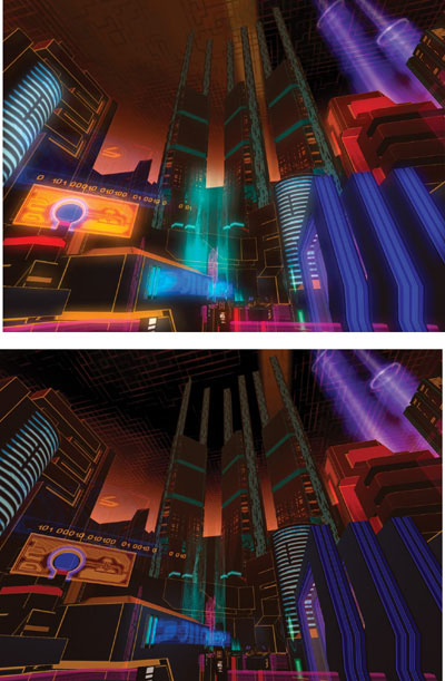
Figure 21-1 A Cityscape With and Without Glow
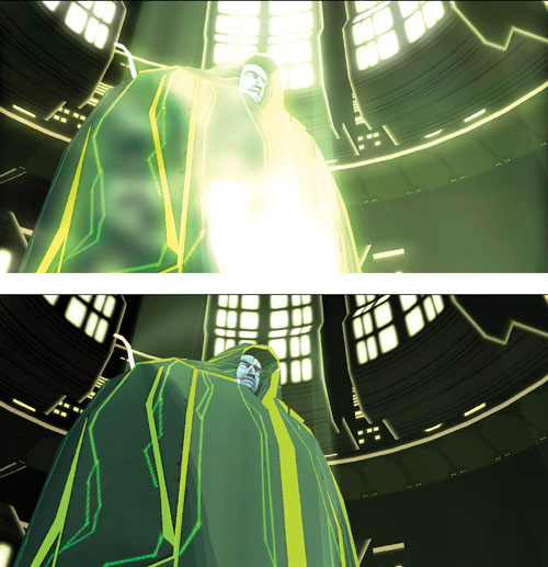
Figure 21-2 A Character With and Without Glow
21.1 Overview of the Technique
There are several approaches to creating glow in a scene. For small point-like objects, a smooth, "glowy" texture can be applied to billboard geometry that follows the objects around the screen. In Tron 2.0, this is used for the Bit character. For large sources of glow or complex glowing shapes, it is best to post-process a 2D rendering of the scene in order to create the glow. This chapter focuses on the post-processing approach, whose steps are outlined in Figure 21-3.
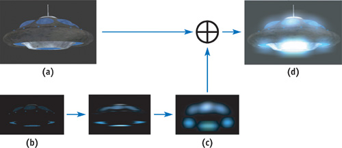
Figure 21-3 Rendering Steps for Creating Real-Time Glow
First, the parts of a scene or model that glow have to be designated by some means that will allow them to be isolated and processed separately from the nonglowing parts. The scene is rendered normally, as it would be with no glow, but it is also rendered using the glow source information to create a texture map that is black everywhere except where the glow sources can be seen. An example of this rendered texture map is shown in Figure 21-3b. This rendered texture map can be used as an ordinary texture in later rendering. It is applied to simple geometry that causes it to be sampled many times at each pixel in a two-step image convolution operation, which blurs the glow source points out into the soft, broad-area glow pattern. Finally, the soft glow is applied on top of the ordinary rendering using additive alpha blending. In this way, the sources of glow are spread out into convincing auras of glow using hardware rendering and texture mapping.
Each of these steps can be done efficiently and quickly on a broad range of graphics hardware. The technique is best suited to hardware that supports Microsoft's Direct3D 8 Vertex and Pixel Shaders 1.1 or later, but a convenient fallback exists for hardware that supports only fixed-function Direct3D 7 rendering. For the older Direct3D 7–era hardware, which has lower fill-rate and texturing performance, the resolution of the render-target textures can be reduced to improve performance while not sacrificing much in terms of image quality. Because the blurred glow texture typically contains only low-frequency features, its resolution can be reduced with little loss in quality. In fact, as explained later, reducing the resolution of the texture render targets is a good way to create larger glows at no additional performance cost.
21.2 Rendering Glows: Step by Step
21.2.1 Specifying and Rendering the Sources of Glow
The first step in rendering glows is to specify which objects or parts of objects are the sources of glow. The color and brightness of these glow sources will translate directly into the color and brightness of the final glow, so this means we can easily control the look of the glow by varying the brightness of the glow sources. These sources could be whole pieces of geometry designated by some object property or flag, or the sources could be restricted to some small part of an object by using texture data. In the latter case, the texture data masks out the parts of an object that do not glow, turning them black in the glow source rendering. The remaining glow source areas can have any desired color and brightness. Using texture data is convenient and artist friendly, and it is our preferred approach.
The glow source mask could be contained in its own separate texture, but it is convenient to use the alpha channel of the ordinary diffuse color texture to hold the mask values. In this case, the texture RGB color is used to render the object normally without alpha blending. When rendering the glow sources, the RGB color is multiplied by the texture alpha channel. Where the alpha value is zero, there will be no source of glow, and as the alpha ramps up to full value, the intensity of the glow sources increases. Figure 21-4 illustrates the texture RGB and alpha channels used to designate sources of glow for a UFO. Additionally, per-vertex or per-object values can be multiplied into the glow source (RGBxalpha) value to animate the glow over time.
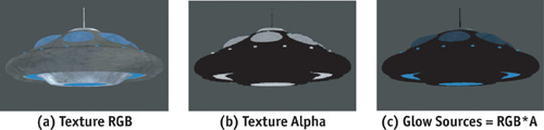
Figure 21-4 Designating Glow Sources
Once the glow sources have been specified, they need to be written to an off-screen render-target texture that we can process to create the soft glow. This is a texture created with the Direct3D 9 D3DUSAGE_RENDERTARGET flag. There are two approaches for getting the glow sources into the texture render target: (1) the entire scene can be rendered to the texture using a method to render the glow sources in color and all nonglowing objects in black, or (2) the scene can be copied from the ordinary back buffer into the texture using the IDirect3DDevice9::StretchRect(..) function. Rendering the entire 3D scene again to the texture can be costly for complex scenes, and it requires an additional depth buffer dedicated to the texture render target, so the StretchRect(..) 2D image copy method is preferred. StretchRect(..) also allows us to resize and filter the back-buffer image in the process of copying it to the texture. This can be used to reduce the resolution and gain performance in processing the texture to create the glows.
For the StretchRect(..) method, the alpha value acting as the glow source mask can be rendered to the destination alpha value of the ordinary back buffer. This will have no effect on the ordinary scene, but in the StretchRect(..) operation it will be copied to the alpha channel of the texture. The alpha channel can then be multiplied by the RGB color to mask out scene objects and leave only the glow sources.
After this step, the glow source texture is blurred to create the soft look of glow. The blur operation smooths high-frequency or point-like features in the source texture, and the result has only broad, low-frequency features. Because of this, the glow and glow sources can be rendered at low resolution, and doing so will not reduce the quality. The glow can be created at one-third or one-quarter of the full-screen resolution in each axis, which will greatly improve the speed of rendering the effect.
Rendering the glow sources at low resolution does affect aliasing on the final glow. As the resolution of the glow source texture is reduced, aliasing of the glow source texture increases, and the source texels become more prone to flicker as objects move around the scene. A single texel of glow source may represent several pixels in the full-resolution image, and this single glow source texel is spread out into a large pattern of glow. This increases the effect of the aliasing, causing the glow to flicker and shimmer as objects move. The degree to which the resolution can be reduced depends on how much flicker is acceptable in the final image. This flickering can be decreased by improving the quality of filtering used when reducing resolution. For example, hardware-accelerated bilinear texture filtering can be used while down-sampling a high-resolution glow source image, and this will greatly diminish the flickering.
21.2.2 Blurring the Glow Sources
Blurring the glow sources spreads them out into a smooth, natural pattern of glow. The blurring is accomplished in hardware using a two-dimensional image-processing filter. The speed at which the glow effect can be created depends largely on how efficiently the blur can be performed. The time required to perform the blur depends on the size, in texels, of the filter used. As the blur filter increases in size to cover more texels, we have to read and write more texels in proportion to the area of the 2D blur. The area is proportional to the blur diameter squared, or d 2. Doubling the diameter of the glow would require processing four times the number of texels. For a blur shape covering 50x50 texels, we'd have to read 2,500 texels for every single pixel of glow that we create! This would make large-area glows very impractical, but fortunately, the nasty diameter-squared cost can be avoided by doing the blur in a two-step operation called a separable convolution. The separable convolution reduces the cost from d 2 to 2d, so it will cost only 100 texel reads at each pixel to create a 50x50 glow. This calculation can be done quickly on modern graphics hardware.
21.2.3 Adapting the Separable Convolution
The technique of separable convolution was designed to save computation in certain special cases, namely, when the convolution kernel can be separated into the product of terms that are independent in each axis. In this case, a two-dimensional convolution of nxm elements can be reduced to two separate one-dimensional convolutions of n and m elements, respectively. This greatly reduces the computation cost of the convolution. Instead of calculating and summing nxm samples at each point, the convolution is reduced to a two-step process requiring only n + m samples. First, an intermediate result image is created by sampling and summing n elements along one axis for each point in the result. Then, a neighborhood of m elements of the intermediate result is sampled along the other axis to create each point in the final result. The weighting factors for each of the n or m samples are the profiles of the convolution along each axis. The key concept, as far as we're concerned, is that the two-step approach can be used with any set of one-dimensional convolution profiles. Even though a particular 2D blur shape may not be mathematically separable, we can use two 1D profiles to approximate the shape. We can create a wide variety of 2D blur shapes by doing only the work of two 1D blurs.
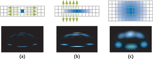
Figure 21-5 The Two-Step Separable Approach for Creating Blurs Efficiently
In-depth information about separable convolutions can be found on the Web at OpenGL.org. For our purposes, the mathematical derivation might seem to restrict the shape of the blurs. This is because the derivation is typically based on only one or two separable functions, such as the two-dimensional Gaussian. Rather than work from the perspective of the derivation where a 2D profile is broken into two separate 1D profiles, we can instead specify any pair of 1D profiles we like. It doesn't matter what the shape of each profile is, as long as they produce some interesting 2D blur result. For the images shown here, we have used two Gaussian curves added together. One curve provides a smooth, broad base, and the other produces a bright spike in the center. Our Direct3D "Glow" demo (NVIDIA 2002) uses various other profiles. Among them is a periodic sawtooth profile that produces an interesting diffraction-like multiple-image effect. The demo and full source code are included on the book's CD and Web site.
21.2.4 Convolution on the GPU
To blur in one axis and then blur that blur in the other axis, we use render-to-texture operations on the GPU. The rendering fetches a local neighborhood of texels around each rendered pixel and applies the convolution kernel weights to the neighborhood samples. A convolution can be performed in a single rendering pass if the GPU can read all of the neighbors in one pass, or the result can be built up over several rendering passes using additive blending to accumulate a few neighbor samples at a time.
Rendering is driven by a simple piece of screen-aligned geometry. The geometry is a simple rectangle usually covering the entire render target and composed of two triangles. Each triangle's vertices have texture coordinates that determine the location at which texels are sampled from the source texture. The coordinates could also be computed in a vertex or pixel shader. If the coordinates are set to range from 0.0 to 1.0 across the render target, then rendering would copy the source texture into the destination. Each pixel rendered would read a texel from its own location in the source texture, resulting in an exact copy. Instead, the texture coordinates for each texture sampler can be offset from each other by one or more texels. In this case, each rendered pixel will sample a local area of neighbors from the source texture. The same pattern of neighbors will be sampled around each rendered pixel. This method is illustrated in Figure 21-6, and it provides a convenient way to perform convolution on the GPU. More information about the technique of neighbor sampling and image processing on the GPU can be found in James 2001 and on the Web at developer.nvidia.com and gpgpu.org.
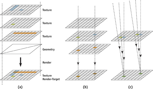
Figure 21-6 Convolution and Image Processing
To perform the blurring convolution operation on the graphics processor, the glow source texture is bound to one or more texture sampler units, and texture coordinates are computed to provide the desired pattern of neighbor sampling. The render target is set to a render-target texture that will hold the result of blurring along the first axis. Call this texture the horizontal blur texture. As each pixel is rendered, several texture samples (neighbor samples) are delivered to the pixel fragment processing hardware, where they are multiplied by the weight factors of the first 1D convolution kernel. Once the horizontal blur has been rendered using one or more passes of rendering to texture, the render target is switched to another texture render target that will hold the final blur. The horizontal blur texture is bound to the input texture samplers, and the texture coordinates and pixel shader weights for the second 1D convolution kernel (the vertical blur) are applied.
After the last blur operation, the glow is ready to be blended into the scene. The render target is switched back to the ordinary back buffer, and the glow texture is added to the scene by rendering a simple rectangle with additive alpha blending.
21.3 Hardware-Specific Implementations
21.3.1 Direct3D 9
With Direct3D 9 ps.2.0–capable hardware, all of the neighbor samples can be read and convolved in a single, complex pixel shader pass. The neighbor-sampling texture coordinate offsets can be computed in a vertex shader program, but the vs.2.0 and ps.2.0 models support only eight iterated texture coordinates. Additional texture coordinates could be computed in the pixel shader, but this may or may not be faster than a multipass approach where only the eight hardware-iterated coordinates are used in each pass. Sample vs.2.0 and ps.2.0 shaders are shown in Listings 21-1 and 21-2. The vertex shader is designed to accept simple, full-screen coverage geometry with vertex coordinates in homogeneous clip space (screen space), where coordinates range from (x, y) = ([-1, 1], [-1, 1]) to cover the full screen. These shaders are used for both the horizontal and vertical blur steps, where only the input constant values change between steps. The constants specify the neighbor-sample placement and kernel weights.
Example 21-1. Direct3D Vertex Shader to Set Texture Coordinates for Sampling Eight Neighbors
vs .2.0 dcl_position v0 dcl_normal v1 dcl_color v2 dcl_texcoord v3 mov oPos,
    v0 // output the vertex position in screen space
        // Create neighbor-sampling texture coordinates by offsetting
        // a single input texture coordinate according to several constants. add
        // oT0,
        v3,
    c0 add oT1, v3, c1 add oT2, v3, c2 add oT3, v3, c3 add oT4, v3, c4 add oT5,
    v3, c5 add oT6, v3, c6 add oT7, v3, c7
Example 21-2. Direct3D Pixel Shader to Sum Eight Weighted Texture Samples
ps .2.0
    // Take 8 neighbor samples, apply 8 conv. kernel weights to them dcl t0.xyzw
    // declare texture coords dcl t1.xyzw dcl t2.xyzw dcl t3.xyzw dcl t4.xyzw
    // dcl t5.xyzw dcl t6.xyzw dcl t7.xyzw dcl_2d s0 declare texture sampler
    // Constants c0..c7 are the convolution kernel weights corresponding
    // to each neighbor sample. texld r0, t0, s0 texld r1, t1, s0 mul
    r0,
    r0, c0 mad r0, r1, c1, r0 texld r1, t2, s0 texld r2, t3, s0 mad r0, r1, c2,
    r0 mad r0, r2, c3, r0 texld r1, t4, s0 texld r2, t5, s0 mad r0, r1, c4,
    r0 mad r0, r2, c5, r0 texld r1, t6, s0 texld r2, t7, s0 mad r0, r1, c6,
    r0 mad r0, r2, c7, r0 mov oC0, r0
Note that in order to sample the texture at the exact texel centers, a texture coordinate offset of half the size of one texel must be added to the texture coordinates. This must be done for Direct3D but is not required for OpenGL, because the Direct3D convention is for coordinates to start from the texel corner, while the OpenGL convention is to start from the texel center. This is a simple adjustment to put into practice. For the vertex shader in Listing 21-1, it requires adding the half-texel offset to each of the constants c0 through c7. This should be done on the CPU.
21.3.2 Direct3D 8
With hardware that supports at most Direct3D 8 vertex and pixel shaders, we are limited to taking only four neighbor samples per pass. Although this limitation will require more rendering passes to build up a convolution of any given size, each pass can be performed very quickly, typically at a rate of several hundred passes per second for render-target textures containing a few hundred thousand texels (textures sized from 256x256 to 512x512). Sample vs.1.1 and ps.1.3 shaders are shown in Listings 21-3 and 21-4.
Example 21-3. Direct3D Vertex Shader Program to Establish Neighbor Sampling
vs .1.1 dcl_position v0 dcl_texcoord v3 mov oPos,
    v0 // output the vertex position in screen space
        // Create neighbor-sampling texture coordinates by offsetting
        // a single input texture coordinate according to several constants. add
        // oT0,
        v3,
    c0 add oT1, v3, c1 add oT2, v3, c2 add oT3, v3, c3
Example 21-4. Direct3D Pixel Shader Program to Sum Four Weighted Texture Samples
ps .1.3 tex t0
    // sample 4 local neighbors tex t1 tex t2 tex t3 // multiply each by kernel
    // weight and output the sum
    mul r0,
    t0, c0 mad r0, t1, c1, r0 mad r0, t2, c2, r0 mad r0, t3, c3, r0
21.3.3 Direct3D 7
Direct3D 7–class hardware lacks the convenient vertex and pixel shading capabilities of modern graphics hardware. It is also typically limited to only two texture samples per pass and will have a much lower fill rate. Still, the blurring convolution can be performed using several overlapping triangles of full-screen coverage geometry. Each pair of triangles, arranged to form a full-screen quad, has the same vertex positions but different vertex texture coordinates. For two-texture multisampling hardware, each quad carries two texture coordinates, and each coordinate is set to sample a different neighbor. Each quad's vertex color attributes are set to the kernel weight for the particular neighbor-sample location, and this vertex color is multiplied by the texture sample value using the fixed-function SetTextureStageState(..) API calls. A stack of these quads can be rendered with additive blending in a single DrawPrimitive(..) call to build up the convolution result.
21.4 Other Uses for Blur
Beyond the use discussed so far—simulating the perception of high-dynamic-range intensity values—this method of convolution and blurring can be used for a variety of other effects. It can be used to compute various degrees of focus for depth-of-field effects, where scene depth information may be used to control the degree of blur. It can be used to soften the edges of projected texture shadows or to accumulate results for percentage-closer filtering of depth shadow maps. A large-area convolution can be applied to an environment map to create an approximate irradiance map for more realistic scene lighting (Ramamoorthi and Hanrahan 2001). Many nonphotorealistic rendering techniques and other special effects can be done with large-area convolutions. Among these are effects for frosted glass, lens flares that simulate diffraction, and approximations of subsurface scattering for rendering skin.
21.5 Adding the Effects to a Game Engine
Next, we focus on how the visual effects were used for Buena Vista Interactive's game, Tron 2.0, in which they played a significant role in the unique visual style of the game. Implementing these effects was surprisingly straightforward. However, some important issues had to be addressed before the effects could be robust enough for use throughout the wide range of situations in the game. Plus, some interesting effects and alternate uses for the glow were discovered during development.
21.5.1 Rendering Context
The first issue we addressed was how to render the source image that would be blurred to create the final screen glow. In Tron 2.0, there were two rendering pipelines: one for rendering the world geometry and one for rendering the models. Both rendering pipelines needed to be extended to support the concept of a rendering context, which allows the scene to be rendered in different ways for different purposes. Two rendering contexts were needed for Tron 2.0. One was normal rendering, which was used to handle the initial rendering of the scene without any screen glow. The second rendering context was glow rendering, which was used when rendering the source image for the glow.
The implementation of a rendering context varies widely among applications, but for illustrative purposes, we will describe how we created the model-rendering pipeline in Tron 2.0. The model rendering is based on a mesh and a collection of render states that indicate how the model should be rendered. These render states are stored as an external resource called a render style. To support the idea of contexts, this system was extended to allow artists to set up a table that would map any render style to a corresponding render style when rendering the glow. Through this mechanism, when rendering the scene normally, the original render style would be used, which would render the model as one would see it if the glow were disabled. Then when rendering the source image for the glow, it would instead use the render style that was found in the map that the artists had set up, which would render the glowing parts of the model. The artists found this system to be very flexible and easy to use, as it gave them control over which objects should glow and how each object should glow. Figure 21-7 shows the plain character model, the artist-created glow texture information, and the glow effect applied to the model.
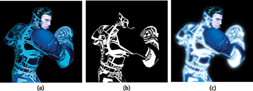
Figure 21-7 Jet, the Hero of , With and Without Glow
21.5.2 Aliasing Issues
The problem of aliasing immediately appeared when we extended the glow effect from a simple test case to a full game scene. The Tron universe is characterized by strips of brightly colored geometry within the scene, almost like neon edging on the characters and their surroundings. In addition, most of the environments are vast, so these glowing strips of geometry range from very close to the camera to far off in the distance. We used a glow texture of 256x256 for Tron 2.0 to allow for a fairly large blur with a minimal number of passes. The downside to this approach, though, was that this caused serious aliasing issues when rendering to the source image, and the aliasing became very apparent as the player moved or looked around.
To address this issue, we added support for artist-controlled fog that would be used only when rendering the source image for the screen glow. The fog would be enabled in large levels and set to black. Because of the additive blending of the screen glow, the black fog in the source image would result in distant objects contributing only faintly, if at all, to the final screen glow. Thus, the aliasing in the distance was made much less noticeable.
It isn't a perfect solution—for example, parts of the scene in the distance will not glow—but it is generally more acceptable visually than the aliasing artifacts are. In addition to avoiding aliasing, the fog was used in several places throughout the game in unanticipated ways to create extra atmosphere, such as that shown in Figure 21-8.
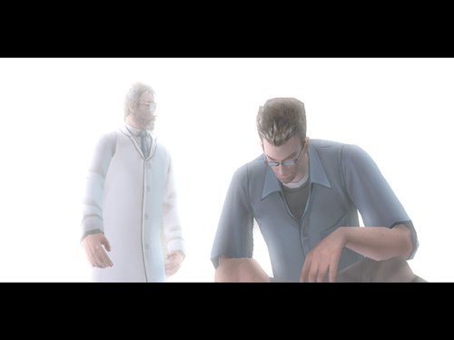
Figure 21-8 Using Fog with Screen Glow
21.5.3 DirectX 7 Accuracy Issues
To fit the blend weight into a color component, the initial DirectX 7 implementation scaled it from the initial range of [0, 1] to an integer between 0 and 255. Most of these weights were very small, though, and thus not well spread over the full range. Consequently, the errors that occurred when converting to an integer resulted in a substantial visual difference between the DirectX 7 and 8 implementations. Even with rounding, the glow still appeared significantly different.
The solution? Perform the rounding, but first determine how much the resulting value differed from the actual value, and then apply the difference to the next weight calculated. For example, a weight of 0.13, when scaled by 255, is 33.15, which rounds to the integer value of 33. Therefore, the weight used for the color would be 33, and the leftover portion (the 0.15) would be added to the next weight to be rendered. As a result, the DirectX 7 and 8 implementations were visually almost identical.
21.5.4 The After-Image Effect
One effect didn't make it into Tron 2.0 because it was discovered too late. It turns out that the previous frame's source texture can be added to the current frame's source texture, resulting in a very nice streaking of the glow as players move or look around. The technique is very simple to implement. It consists of an extra texture surface so the source image can be preserved for the following frame, and an additive blend that adds the previous source image to the current source image. This technique works by saving the image immediately before the blur is applied and then applying the blur. The saved image is added to the source image of the next frame, but it is dimmed slightly. As this process is repeated over a number of frames, it allows objects to fade out of the glow instead of instantly disappearing, which not only makes the effect more compelling, but also helps hide aliasing of the source image.
The degree of dimming applied to the previous frame before adding the frame to the current frame's glow source can be changed dynamically, resulting in a wide range of appearance. For example, by dimming the previous frame significantly, there will be very little after-image, and it will appear to users as only a brief burn-in of light in their retina, giving the look of a much brighter light. By dimming the previous frame less before adding it, the blurring and streaking becomes much more apparent and has the effect on the player of appearing drunk or near death.
One alternative does not require an additional buffer. We can use the previous frame's final screen-glow texture after the blur, which saves memory because the source image does not need to be preserved. However, this solution does have certain issues. If the previous frame's glow texture is too bright, it can bleed out of control when recursively added, continually blurring outward in each frame, eventually resulting in a fully white screen glow. To avoid this case, we have to be careful when setting up the blend weights and determining how much to dim the previous frame.
21.5.5 The Variable Ramping Effect
The screen glow must use a certain set of parameters—such as blending weights and fog—to create the final blur for a single frame. However, that doesn't mean the parameters can't change from frame to frame. In fact, by varying any of these parameters, you can achieve a variety of interesting effects. For example, in one of the levels of Tron 2.0, the player is inside a corrupted server that has a sickly green glow. To convey the unstable feeling, the blend weights of the blur were ramped from low to high to create a dull pulsing of the screen glow. See Figure 21-9.
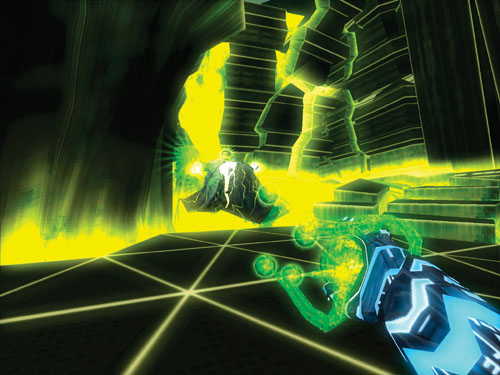
Figure 21-9 A Pulsing Screen Glow Creates a Sickly Feel
Although not used in the game, other effects can be just as easily achieved. For example, by ramping the screen glow fog in and out, or changing the color of the fog, you can easily and efficiently make the atmosphere of a level feel as if it were constantly changing.
21.6 Conclusion
Large blurs and convolutions can be computed efficiently in real time on a broad range of graphics hardware. The code for processing and creating these effects is easily encapsulated into a few C++ classes or a small library. These classes and sample code are available on NVIDIA's Developer Web site, developer.nvidia.com. The effect requires additional data to specify the brightness of glow sources, and this data can be incorporated into existing texture assets, namely the texture alpha channel. The effect offers intuitive controls for the brightness and shape of the glow. The ability to apply large-area convolutions to full-screen rendering is useful for a wide variety of effects. It is key to depicting bright objects in a scene and can greatly enhance the look and quality of real-time rendering.
Screen glow is one of the rare effects that are robust enough to be easily extended for use in nearly every situation, yet it is versatile enough to allow numerous additional effects to be created through it. The final effect is subtle but powerful, and well worth prototyping in any game.
21.7 References
Chiu, K., M. Herf, P. Shirley, S. Swamy, C. Wang, and K. Zimmerman. 1993. "Spatially Nonuniform Scaling Functions for High Contrast Images." Graphics Interface '93, pp. 245–253.
GPGPU Web site. 2003. http://www.gpgpu.org
James, Greg. 2001. "Operations for Hardware-Accelerated Procedural Texture Animation." In Game Programming Gems 2, edited by Mark DeLoura, pp. 497–509. Charles River Media.
Kawase, Masaki. 2003. Personal Web site. http://www.daionet.gr.jp/~masa/column/2003-03-21.html
Nakamae, Eihachiro, Kazufumi Kaneda, Takashi Okamoto, and Tomoyuki Nishita. 1990. "A Lighting Model Aiming at Drive Simulators." In Proceedings of SIGGRAPH 90, pp. 395–404.
NVIDIA Developer Web site. 2003. http://developer.nvidia.com
OpenGL.org Web site. 2003. "Advanced Graphics Programming Techniques Using OpenGL." Course notes, SIGGRAPH 99. Mathematics of separable convolution. http://www.opengl.org/resources/tutorials/sig99/advanced99/notes/node235.html
Ramamoorthi, Ravi, and Pat Hanrahan. 2001. "An Efficient Representation for Irradiance Environment Maps." In Proceedings of SIGGRAPH 2001, pp. 497–500. Available online at http://graphics.stanford.edu/papers/envmap
Spencer, Greg, Peter S. Shirley, Kurt Zimmerman, and Donald P. Greenberg. 1995. "Physically Based Glare Effects for Digital Images." In Proceedings of SIGGRAPH 95, pp. 325–334.
We offer tremendous thanks to the Developer Technology group at NVIDIA and to Monolith Productions for encouraging and assisting in the development of this technique and for transforming a simple tech demo into gorgeous visuals in the final shipping game.
Copyright
Many of the designations used by manufacturers and sellers to distinguish their products are claimed as trademarks. Where those designations appear in this book, and Addison-Wesley was aware of a trademark claim, the designations have been printed with initial capital letters or in all capitals.
The authors and publisher have taken care in the preparation of this book, but make no expressed or implied warranty of any kind and assume no responsibility for errors or omissions. No liability is assumed for incidental or consequential damages in connection with or arising out of the use of the information or programs contained herein.
The publisher offers discounts on this book when ordered in quantity for bulk purchases and special sales. For more information, please contact:
U.S. Corporate and Government Sales
(800) 382-3419
corpsales@pearsontechgroup.com
For sales outside of the U.S., please contact:
International Sales
international@pearsoned.com
Visit Addison-Wesley on the Web: www.awprofessional.com
Library of Congress Control Number: 2004100582
GeForce™ and NVIDIA Quadro® are trademarks or registered trademarks of NVIDIA Corporation.
RenderMan® is a registered trademark of Pixar Animation Studios.
"Shadow Map Antialiasing" © 2003 NVIDIA Corporation and Pixar Animation Studios.
"Cinematic Lighting" © 2003 Pixar Animation Studios.
Dawn images © 2002 NVIDIA Corporation. Vulcan images © 2003 NVIDIA Corporation.
Copyright © 2004 by NVIDIA Corporation.
All rights reserved. No part of this publication may be reproduced, stored in a retrieval system, or transmitted, in any form, or by any means, electronic, mechanical, photocopying, recording, or otherwise, without the prior consent of the publisher. Printed in the United States of America. Published simultaneously in Canada.
For information on obtaining permission for use of material from this work, please submit a written request to:
Pearson Education, Inc.
Rights and Contracts Department
One Lake Street
Upper Saddle River, NJ 07458
Text printed on recycled and acid-free paper.
5 6 7 8 9 10 QWT 09 08 07
5th Printing September 2007
- Contributors
- Copyright
- Foreword
- Part I: Natural Effects
-
- Chapter 1. Effective Water Simulation from Physical Models
- Chapter 2. Rendering Water Caustics
- Chapter 3. Skin in the "Dawn" Demo
- Chapter 4. Animation in the "Dawn" Demo
- Chapter 5. Implementing Improved Perlin Noise
- Chapter 6. Fire in the "Vulcan" Demo
- Chapter 7. Rendering Countless Blades of Waving Grass
- Chapter 8. Simulating Diffraction
- Part II: Lighting and Shadows
-
- Chapter 9. Efficient Shadow Volume Rendering
- Chapter 10. Cinematic Lighting
- Chapter 11. Shadow Map Antialiasing
- Chapter 12. Omnidirectional Shadow Mapping
- Chapter 13. Generating Soft Shadows Using Occlusion Interval Maps
- Chapter 14. Perspective Shadow Maps: Care and Feeding
- Chapter 15. Managing Visibility for Per-Pixel Lighting
- Part III: Materials
- Part IV: Image Processing
- Part V: Performance and Practicalities
-
- Chapter 28. Graphics Pipeline Performance
- Chapter 29. Efficient Occlusion Culling
- Chapter 30. The Design of FX Composer
- Chapter 31. Using FX Composer
- Chapter 32. An Introduction to Shader Interfaces
- Chapter 33. Converting Production RenderMan Shaders to Real-Time
- Chapter 34. Integrating Hardware Shading into Cinema 4D
- Chapter 35. Leveraging High-Quality Software Rendering Effects in Real-Time Applications
- Chapter 36. Integrating Shaders into Applications
- Part VI: Beyond Triangles
- Preface