
GPU Gems
GPU Gems is now available, right here, online. You can purchase a beautifully printed version of this book, and others in the series, at a 30% discount courtesy of InformIT and Addison-Wesley.
The CD content, including demos and content, is available on the web and for download.
Chapter 12. Omnidirectional Shadow Mapping
Philipp S. Gerasimov
iXBT.com
12.1 Introduction
One of the most difficult problems in real-time computer graphics is generating high-quality shadows. Yet, the appearance of such shadows is one of the most important factors in achieving graphic realism. In computer-generated scenes, an object's shadow enhances our perception of the object and the relationship between objects. In computer games, shadows—along with lighting, music, and special effects—play a very important role in portraying a realistic game atmosphere. For example, shadows are a major part of the story line in id Software's Doom 3, one of the most technologically advanced games. Figures 12-1 and 12-2 show examples of shadows from our own demo, which is provided on the book's CD and Web site.
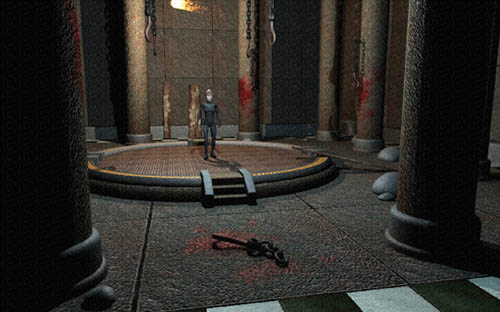
Figure 12-1 Screenshot of Our Demo, Showing a Light Source Flying Above a Character
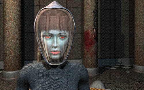
Figure 12-2 A Close-Up of the Character in Our Demo
GPUs now allow us to create images previously available only in professional 3D offline-rendering programs. The geometry processors in modern GPUs can process millions of primitives per frame, letting us design complex worlds. With the advent of per-pixel shading, we can produce realistic materials using complex mathematical and physically based models of lighting.
Two popular methods are available for visualizing shadows in real-time computer graphics: stencil shadows and shadow mapping.
12.1.1 Stencil Shadows
The stencil shadows method, which is demonstrated in Doom 3, is used widely by game developers. It offers advantages such as the large number of GPUs that support it (the only essential hardware feature is support for an eight-bit stencil buffer), its independence from the type of light source, and the high quality of its generated shadows. However, the stencil shadows approach has some serious disadvantages: it's heavily dependent on CPU work, it can produce only hard shadows, it uses a large amount of fill rate (which means that even though a GPU may support the technique, it could run poorly), and it cannot be used with hardware-tessellated surfaces.
12.1.2 Shadow Mapping
The shadow-mapping algorithm came to computer graphics in 1978 when it was introduced by Lance Williams (Williams 1978). Today, this method is used in a multitude of Hollywood movies that contain computer graphics and special effects. Shadow mapping projects a special dynamically created texture on scene geometry to calculate shadows. It lets you render hard and soft shadows, as well as shadows from different types of light sources. Plus, it works with hardware-tessellated surfaces and with GPU-animated meshes (such as skinned meshes).
A number of GPU manufacturers, including NVIDIA, support shadow mapping directly in their hardware and promise to enhance this support in the future. The NVIDIA GeForce3, GeForce4 Ti, and all the GeForce FX (and more recent) GPUs support hardware shadow maps through both DirectX and OpenGL. (However, we do not use the native hardware shadow-mapping functionality in this chapter.) The possibilities offered by the NVIDIA CineFX architecture—including support for long fragment programs with true floating-point precision as well as floating-point texture formats—enable a new level of quality in shadow rendering.
12.2 The Shadow-Mapping Algorithm
12.2.1 Conditions
Shadow mapping lets us visualize shadows cast from different types of light sources, such as directional lights, point lights, and spotlights. The type of light source dictates the technology we need to use. This chapter focuses on visualizing shadows cast from point light sources. Point light sources are widely used in computer games, and the quality of shadows cast by objects illuminated by these lights is very important.
We also have these additional conditions:
- Cube maps, traditionally used in computer graphics to implement environment reflections, are the building blocks of our shadow-mapping algorithm.
- We focus our implementation on DirectX 9–compatible graphics hardware (for example, products in the GeForce FX family from NVIDIA, or the Radeon 9500 and more recent products from ATI).
- We use DirectX as the graphics API (but our algorithm works just as well in OpenGL).
- We take advantage of vertex and pixel shaders written in a high-level language.
- We use HLSL (but Cg is ideal for this task, too).
12.2.2 The Algorithm
There are two primary phases in using omnidirectional shadow maps: creating the shadow map and projecting it. In the creation phase, we render the squared distance from the light source of all objects that cast shadows into the shadow map texture (we'll see why the distance is squared a little later). In the projection phase, we render all the objects that receive shadows, and we compare the squared distance from the rendered pixel to the light source.
The following technique fills all six faces of a cube map, in all directions: +x, -x, +y, -y, +z, -z. The shadow maps can be either precalculated (for static scenes) or re-rendered every frame. We focus primarily on re-rendering the shadow map each frame for fully dynamic shadows. All objects cast a shadow, and receive a shadow, from each light source. And all objects self-shadow. We use a single shadow map for all light sources, creating an image with multipass rendering and performing one pass for each light source.
Listing 12-1 is an example of pseudocode for this algorithm.
Because we use a multipass algorithm (that is, making one pass for each light source), all objects must be composited into the frame buffer. To reduce overdraw and improve performance, we render a depth-only pass first. This standard technique ensures that all subsequent lighting passes occur only on visible pixels. Rendering to depth-only is very fast (many GeForce FX GPUs have double-speed "depth-only" rendering features), so it requires minimal overhead, even in low-overdraw situations. Transparent objects are not rendered in the depth-only pass, because transparent objects do not update the depth buffer. See Listing 12-2.
Example 12-1. Pseudocode for the Omnidirectional Shadow-Mapping Algorithm
for (iLight = 0; iLight < NumberOfLights; iLight++)
{
  // Fill the shadow map.
  for (iObject = 0; iObject < NumberOfObjects; iObject++)
  {
    RenderObjectToShadowMap(iLight, iObject);
  }
  // Lighting and shadow mapping.
  for (iObject = 0; iObject < NumberOfObjects; iObject++)
  {
    LightAndShadeObject(iLight, iObject);
  }
}
Example 12-2. Depth-Only Rendering
// Clear color and depth buffers ClearAllBuffers();
// Fill z-buffer
for (iObject = 0; iObject < NumberOfObjects; iObject++)
{
  RenderObjectToZBufferOnly(iObject);
}
12.2.3 Texture Format
The type of texture format used is an important factor in this algorithm. We consider two formats: floating-point textures and integer 32-bit RGBA textures with packing/unpacking of the depth value into the color channels.
The floating-point texture format is ideal for shadow mapping because it allows for high-precision depth values. However, these textures are much slower than integer RGBA textures and are supported by only a limited number of GPUs. On the other hand, integer 32-bit RGBA textures are fast and are supported by most 3D hardware.
To conserve the high precision of calculation, however, we must pack depth values into the color channels of textures and unpack each value when performing the depth-compare for shadow mapping. We consider both methods and let you choose the one that's more convenient.
12.2.4 The Size of the Shadow Map
The size of the shadow map influences the shadow's quality and rendering speed. The size depends on the capabilities of the target hardware, the required quality, and the position of the shadow in relationship to the camera. Of course, a larger shadow map generally produces better results.
Because we use cube map textures, we have to keep in mind that we have six color surfaces and an additional z-buffer. For 32-bit textures and a 1024x1024 resolution, we'll need 4 x (6 + 1) x 1024 x 1024 bytes of video memory, or 28 MB! This highlights the importance of using a single shadow map for all light sources.
Section 12.3 examines each step of our algorithm.
12.2.5 The Range of Values for Geometry
To minimize rendering artifacts, we put all our geometry into a -0.5...+0.5 range (or 0..1). This adds accuracy to our calculations, especially if we use 16-bit precision and integer textures. We can scale our geometry at load time or in the vertex shader, using vertex shader code such as this:
o.vPositionWorld = mul(vPosition, matWorld) * fGeometryScale;12.3 Implementation
12.3.1 System Requirements
These are our system requirements:
- Hardware that supports vertex shaders (vs.1.1+) and pixel shaders (ps.2.0+)
- Hardware capability for rendering into cube maps
- If using floating-point textures: support for a single-component floating-point cube-map texture format, such as D3DFMT_R16F or D3DFMT_R32F, with the D3DUSAGE_RENDERTARGET flag
- If using integer textures: support for the D3DFMT_A8R8G8B8 cube texture format, with the D3DUSAGE_RENDERTARGET flag
12.3.2 Resource Creation
We can create all the required objects and textures (the shadow map texture, the depth buffer, and the shaders) using several useful Direct3D library functions:
D3DXCreateCubeTexture() D3DXCreateRenderToEnvMap() D3DXCreateEffectFromFile()12.3.3 Rendering Phase 1: Rendering into the Shadow Map
Next, we render into the shadow map. We'll render our objects into each face of the cube map from the point of view of the light source, following these requirements:
- The field of view must be 90 degrees.
- The view matrix for each face must be created properly. We can create these matrices from the up, down, east, west, north, and south vectors from the point of view of the light source.
The Vertex Shader
In the vertex shader, we write out the scaled world-space position of the vertex for the pixel shader. Or, we can write out the light direction and save one pixel shader instruction computing the world-space light vector.
The Pixel Shader
We can use either a floating-point texture or an integer texture.
-
When we use floating-point textures, we write out the squared distance from the pixel to the light source, as in this pixel shader code:
return dot(vLight, vLight)Why do we use squared distance? Because it's faster to compute—it's just a dot product, and no square root operation is necessary. We use squared distance when filling the shadow map, and we will use squared distance when accessing the shadow map in the base rendering pass. This saves pixel shader instructions twice. But using the squared distance can cause some precision problems, so we need to be careful when using it.
- When we use integer textures, we need to pack the squared distance value and write it into the color
channel. How can we pack a floating-point number into an integer texture? Here are two ways:
-
Out.r = SquaredDistance * 2 ^ 0 Out.g = SquaredDistance * 2 ^ 8 Out.b = SquaredDistance * 2 ^ 16 Out.a = SquaredDistance * 2 ^ 24 float4 vPack = {1.0f, 256.0f, 65536.0, 16777216.0f}; return vPack * dot(vLight, vLight); -
Out.r = floor(fDepth) / 256.0;
Out.g = frac(fDepth);
float fDepth = dot(vLight, vLight);
return float(floor(fDepth) / 256.0, frac(fDepth), frac(fDepth), frac(fDepth));
-
By writing frac(fDepth) into the green and alpha channels, we save this pixel shader instruction (otherwise, we need an additional instruction to fill these channels):
mov r2.gba, r0.g
            // r0.g contains frac(fDepth)
Method 1 is computationally cheaper, but the second one gives you higher precision.
12.3.4 Rendering Phase 2: Base Rendering
The base rendering phase has two main parts:
- Rendering objects only to the z-buffer (z-only pass), which requires these steps:
- Disabling rendering into the color channel
- Enabling rendering into the z-buffer
- Rendering all objects into the z-buffer (only)
- Making a shading (lighting times shadow) pass for each light source
12.3.5 The Lighting Calculation
We need to calculate the lighting at each pixel from the light source, and we can use any lighting model (such as per-pixel Phong, Blinn, or Oren-Nayar).
12.3.6 The Shadow Calculation
Calculating the shadow requires these steps:
- Calculate the squared distance from the current pixel to the light source.
- Project the shadow map texture onto the current pixel.
- Fetch the shadow map texture value at the current pixel.
- Compare the calculated distance value with the fetched shadow map value to determine whether or not we're in shadow.
For floating-point textures, we just use the x component of the fetched texture sample.
Here is the pixel shader code:
float fDepth = fDistSquared - fDepthBias;
float3 vShadowSample = texCUBE(ShadowMapSampler, -vLight.xyz);
float fShadow = (fDepth - vShadowSample.x < 0.0f) ? 1.0f : 0.0f;
fDistSquared was computed previously in the pixel shader. For integer textures, we must unpack the value from the color channels of the fetched texture sample.
-
DepthValue = ShadowSample.r / 1 + ShadowSample.g / 256 + ShadowSample.b / 65536 + ShadowSample.a / 16777216 -
DepthValue = ShadowSample.r * 256 + ShadowSample.g
Here is the pixel shader code:
float fDepth = fDistSquared - fDepthBias;
float4 vShadowSample = texCUBE(ShadowMapSampler, -vLight.xyz);
float fShadow = (fDepth - dot(vShadowSample, vUnpack) < 0.0f) ? 1.0f : 0.0f;
12.3.7 Tips and Tricks
- There are a number of different ways you can compute depth bias:
- fDistSquared - vShadowSample.x—artifacts are very possible.
- (fDistSquared - DepthBias) - vShadowSample.x—the squared distance is not linear.
- (fDistSquared * DepthBias) - vShadowSample.x—this method works best in practice.
- Light direction: Move the light direction calculation into the vertex shader. The light direction is linear and can easily be calculated per vertex.
- Opposite light direction: We need the opposite light direction for fetching from the shadow map. But the texld pixel shader instruction does not support the "negate" modifier, so if we use texCUBE(ShadowMapSampler, -vLight.xyz), we'll get an extra "add" instruction with every fetch. So, we can move this calculation into the vertex shader and interpolate -vLight.xyz instead of vLight.xyz.
- Preprocessor directives with HLSL and Cg shaders: Use preprocessor directives for different options—such as floating-point/integer textures, hard/soft shadows, and full/half/fixed precision—to reduce the number of shaders you need to write.
- Pixel shader precision: Use half precision for most shadow calculations. It's sufficient, and you will get extra speed on some hardware. If you see artifacts, however, use full precision.
12.3.8 Finalizing the Shading Pass (Lighting x Shadow)
The last step is to write the pixel color value based on the calculated lighting and shadowing. For each light source, we add the calculated lighting into the back buffer by repeating the shadow-writing and shading passes for all objects. When we finish processing all the light sources, we get a scene with dynamic lighting and shadowing.
12.4 Adding Soft Shadows
Looking at our scene, we notice that the shadows' edges are aliased and "hard." The level of aliasing depends on the size of the shadow map and the amount of magnification during projection. To reduce the appearance of these artifacts, we create a "softer" shadow by fetching multiple samples from the shadow map and averaging the results. Because real-world light sources are rarely perfect point sources, this action will also provide a more realistic shadow.
Listing 12-3 shows some sample code.
Example 12-3. Making a Softer Shadow
float fShadow = 0;
for (int i = 0; i < 4; i++)
{
  float3 vLightDirection = -vLight.xyz + vFilter[i];
  float4 vShadowSample = texCUBE(ShadowMapSampler, vLightDirection);
  fShadow += (fDepth - vShadowSample.x < 0.0f) ? 0.25f : 0.0f;
}
Note that we first compare the squared distances and then average the results of the comparison. This is called percentage-closer filtering and is the correct way to average multiple shadow map tests. (See Chapter 11 of this book, "Shadow Map Antialiasing," for a detailed discussion of this technique.)
We can save some pixel shader instructions when calculating -vLight.xyz + vFilter[i] values if we move it into the vertex shader.
If we choose different range values for vFilter[i], we'll get different levels of softness for the shadow, ranging from a slight antialiasing effect to a very blurry shadow. The larger the filter kernel we define, the more samples we need to take to avoid banding artifacts. Obviously, taking more samples equals processing more instructions and more texture fetches, which can reduce performance in shader-bound situations. Although this technique can produce a "softer" look for the shadows, the shadows are of course not accurate soft shadows, because they do not take into account the relationships between occluders, receivers, and the size of the light source. (See Chapter 13, "Generating Soft Shadows Using Occlusion Interval Maps," for more on soft shadows.)
12.5 Conclusion
With the new capabilities of DirectX 9–class hardware, new algorithms for improving visual quality become possible and easier to implement. Using hardware shaders, we can create realistic, dynamic shadows from any number of point light sources, and we can even implement basic "soft" shadows.
With the current first-generation DirectX 9–class hardware, this algorithm is not quite fast enough to be practical (although it is definitely real time). That's because of the large number of renderings from the point of view of the light, and the long pixel shaders necessary for "soft" shadowing effects. But as always, much faster graphics hardware is right around the corner, and advances in performance will make these algorithms practical for implementation in real, shipping games.
12.6 References
Williams, Lance. 1978. "Casting Curved Shadows on Curved Surfaces." In Proceedings of the 5th Annual Conference on Computer Graphics and Interactive Techniques, pp. 270–274.
The author would like to thank Chris Wynn and John Spitzer of NVIDIA and Guennadi Riguer of ATI.
Copyright
Many of the designations used by manufacturers and sellers to distinguish their products are claimed as trademarks. Where those designations appear in this book, and Addison-Wesley was aware of a trademark claim, the designations have been printed with initial capital letters or in all capitals.
The authors and publisher have taken care in the preparation of this book, but make no expressed or implied warranty of any kind and assume no responsibility for errors or omissions. No liability is assumed for incidental or consequential damages in connection with or arising out of the use of the information or programs contained herein.
The publisher offers discounts on this book when ordered in quantity for bulk purchases and special sales. For more information, please contact:
U.S. Corporate and Government Sales
(800) 382-3419
corpsales@pearsontechgroup.com
For sales outside of the U.S., please contact:
International Sales
international@pearsoned.com
Visit Addison-Wesley on the Web: www.awprofessional.com
Library of Congress Control Number: 2004100582
GeForce™ and NVIDIA Quadro® are trademarks or registered trademarks of NVIDIA Corporation.
RenderMan® is a registered trademark of Pixar Animation Studios.
"Shadow Map Antialiasing" © 2003 NVIDIA Corporation and Pixar Animation Studios.
"Cinematic Lighting" © 2003 Pixar Animation Studios.
Dawn images © 2002 NVIDIA Corporation. Vulcan images © 2003 NVIDIA Corporation.
Copyright © 2004 by NVIDIA Corporation.
All rights reserved. No part of this publication may be reproduced, stored in a retrieval system, or transmitted, in any form, or by any means, electronic, mechanical, photocopying, recording, or otherwise, without the prior consent of the publisher. Printed in the United States of America. Published simultaneously in Canada.
For information on obtaining permission for use of material from this work, please submit a written request to:
Pearson Education, Inc.
Rights and Contracts Department
One Lake Street
Upper Saddle River, NJ 07458
Text printed on recycled and acid-free paper.
5 6 7 8 9 10 QWT 09 08 07
5th Printing September 2007
- Contributors
- Copyright
- Foreword
- Part I: Natural Effects
-
- Chapter 1. Effective Water Simulation from Physical Models
- Chapter 2. Rendering Water Caustics
- Chapter 3. Skin in the "Dawn" Demo
- Chapter 4. Animation in the "Dawn" Demo
- Chapter 5. Implementing Improved Perlin Noise
- Chapter 6. Fire in the "Vulcan" Demo
- Chapter 7. Rendering Countless Blades of Waving Grass
- Chapter 8. Simulating Diffraction
- Part II: Lighting and Shadows
-
- Chapter 9. Efficient Shadow Volume Rendering
- Chapter 10. Cinematic Lighting
- Chapter 11. Shadow Map Antialiasing
- Chapter 12. Omnidirectional Shadow Mapping
- Chapter 13. Generating Soft Shadows Using Occlusion Interval Maps
- Chapter 14. Perspective Shadow Maps: Care and Feeding
- Chapter 15. Managing Visibility for Per-Pixel Lighting
- Part III: Materials
- Part IV: Image Processing
- Part V: Performance and Practicalities
-
- Chapter 28. Graphics Pipeline Performance
- Chapter 29. Efficient Occlusion Culling
- Chapter 30. The Design of FX Composer
- Chapter 31. Using FX Composer
- Chapter 32. An Introduction to Shader Interfaces
- Chapter 33. Converting Production RenderMan Shaders to Real-Time
- Chapter 34. Integrating Hardware Shading into Cinema 4D
- Chapter 35. Leveraging High-Quality Software Rendering Effects in Real-Time Applications
- Chapter 36. Integrating Shaders into Applications
- Part VI: Beyond Triangles
- Preface