
GPU Gems
GPU Gems is now available, right here, online. You can purchase a beautifully printed version of this book, and others in the series, at a 30% discount courtesy of InformIT and Addison-Wesley.
The CD content, including demos and content, is available on the web and for download.
Chapter 6. Fire in the "Vulcan" Demo
Hubert Nguyen
NVIDIA
This chapter talks about the "Vulcan" demo that the NVIDIA demo team created for the launch of the GeForce FX 5900 Ultra. Inspired by the Balrog creature in The Lord of the Rings movies, our goal was to display a monster that would be the source of raging flames, as shown in Figure 6-1. The flames and smoke had to be massive and sometimes overwhelming. Our goal in writing this chapter is to share our experience of how we created the effect and to discuss possible enhancements. In the end, we hope that this exploration will help you to create more sophisticated fire effects in your own applications.
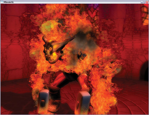
Figure 6-1 A Screen Capture from the "Vulcan" Demo
6.1 Creating Realistic Flames
When we started working on the demo, we first tried two solutions that looked promising: fully procedural flames and screen-space 2D distortion-based flames.
The fully procedural approach consumed very little memory, yet it created an appealing flame effect. To produce well-defined flames, we had to display thousands of particles, and processing all of those vertices and pixels put a heavy load on the CPU and the GPU. Figure 6-2 shows the effect.
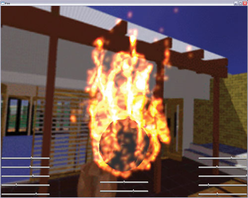
Figure 6-2 Five Thousand Particles Used to Create Fire
The 2D distortion-based flames used a GPU-generated perturbation function that altered a flame shape to give it a realistic motion. The distortion involved making several render-to-texture passes and shifting 2D texture coordinates. Although it consumed more memory than the particle system technique (because we had to allocate several render targets), the effect is perfect for creating candle-like flames. See Figure 6-3.
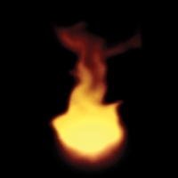
Figure 6-3 A Flame Created Using 2D Flow
The screen-aligned nature of the effect made it sensitive to the camera view angle (constraints were needed for top and bottom views) and to motion in general (moving toward and away from the camera didn't work well in 2D sometimes). Integrating smoke was also a challenge.
Both procedural techniques have strong advantages, but they didn't meet our goal of creating a believable raging fire with smoke in a real-time, user-controllable environment. So we turned to video-textured sprites to make the fire more realistic. See Figure 6-4. Although full procedural and physically based flame generation is clearly the wave of the future, some cutting-edge movies (such as The Lord of the Rings) still use special effects composed of sprite-based flames.
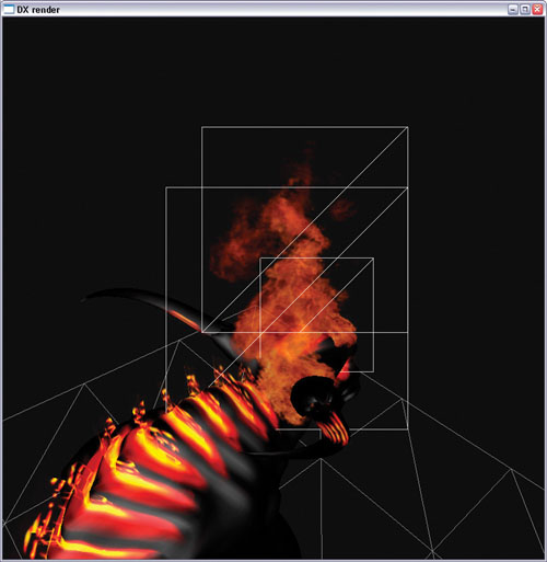
Figure 6-4 Three Video-Textured Fire Particles
6.2 Implementing Animated Sprites
In order to create the fire enveloping the Vulcan character, first we needed to decide where the fire was coming from. Using our modeling tool, we placed emitters on the character. Each emitter can be adjusted for size, density (that is, particles per second), texture, particle lifespan, and so on. This flexibility proved very useful, because it allowed us to tweak the fire's appearance to suit our needs. We could then spawn some particles and draw the flames, as shown in Figure 6-5.
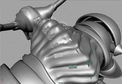
Figure 6-5 Spawning Flames
6.2.1 Animating Flames and Smoke
Because the consumption of texture memory increased rapidly with the number of video textures we used, we had to limit ourselves to three animations: two for flames and one for smoke. At 64 frames each, 192 frames of animation were dedicated to fire and smoke, and 64 were allocated for other use, such as the flying animated spark in the demo. A 3D texture requires that the number of slices (or here, frames) be a power of two, so we used 256 frames. Had we wanted to add more, the minimum increase would have been to 512 frames—doubling the texture-memory footprint of this effect. See Figure 6-6.
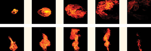
Figure 6-6 Video Footage Used to Create the Fire Effect
Custom Smoke Generator
At first we thought about using video footage for the smoke as we did for the flames, but it's hard to find suitable footage of a single puff of smoke, with just the right lighting, color, and so on.
We ended up using a particle system to create a smoke generator, because the desired lighting could be achieved with various techniques, such as ray casting. We tweaked the lighting to fit the fire environment and, most important, we maintained control over the colors. We gave the smoke particles a rolling motion on the x axis so the smoke appeared to be folding into itself. This detail didn't cost anything, but it added a lot to the overall smoke effect. The result was a good integration of real fire footage and procedural smoke. See Figures 6-7 and 6-8.

Figure 6-7 Procedurally Generated Smoke
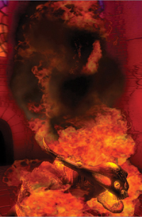
Figure 6-8 Real-Time Smoke in the Demo
If we had used a simple smoke lighting algorithm, we might have been able to use the procedural smoke directly in the demo. However, lack of time prevented us from exploring this possibility, given that smoke lighting is a complex problem to solve.
6.2.2 Adding Variety to the Flames
Given the small number of animated frames that we could allocate to the effect, we expected that repetition of the same image in the animation could be a serious issue. There are simple ways to hide repetition and artificially add more variety. We started with a single animation, and it worked even better with two or more. In addition, we created particles with a random percentage of difference for a number of attributes: size, position, rate of decay, animation start frame, global transparency, and so on.
We also chose not to use hardware point sprites but instead generated our own quads. This technique allowed us to create custom texture coordinates to flip the animation on one or two axes. In the demo, we used horizontal and vertical flipping (along the u and v axes). This worked well, but arbitrary rotations would have been even better. See Figure 6-9.
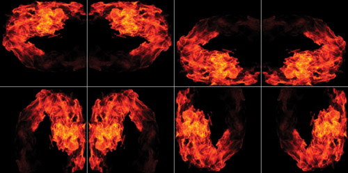
Figure 6-9 Variations Produced by Custom Texture Coordinates
Because we had a second animation (taken from the video clips shown in Figure 6-6), we blended two kinds of sprites: A and B. Creating different percentages of A and B types added diversity to the flames and helped control the look of the effect. See Figure 6-10.
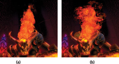
Figure 6-10 Improving Fire in the Demo
6.2.3 Storing the Animation
We found it helpful to store the flames in a volume texture (also known as a 3D texture). Doing so resulted in interframe blending that compensated for the low number of animation frames. And it was convenient to handle because incrementing the z-texture coordinate "played" the animation. The whole animation appeared as a single texture to the application, which is great if the particles are sorted. Volume textures require that all sides (width, height, and depth) be a power of two. In our case, we used a compressed 256x256x256 B8G8R8A8 texture, which is 16 MB. If you don't have much memory available (because you are running on a low-end card or on a console), you can try shrinking the volume; we reduced the volume size to 64x64x256, and the results still looked great.
6.2.4 Blending Flames and Smoke
When we first started to implement the flames, like many game developers, we used additive blending, because it allows one to draw all the sprites independently (that is, in no particular order). Visually, additive blending is recognizable because it saturates color and thus removes most of the color control from the artists—whom we want to empower as much as possible. Saturation made the flames look cartoon-like, not realistic. Also, additive blending makes mixing flames and smoke even trickier—especially while rendering to the limited range and precision of an A8R8G8B8 target.
The switch to alpha blending solved those two issues, at the cost of sorting a few hundred particles per frame. The performance impact of sorting turned out to be negligible. See Figures 6-11 and 6-12.
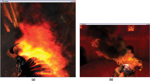
Figure 6-11 Mixing Fire and Smoke
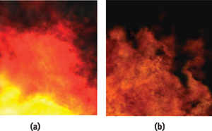
Figure 6-12 Controlling Color
6.3 Particle Motion
We expected the motion of the particles to involve nothing more than simple upward movement. However, getting the particle motion right required more attention than we had anticipated. Because the video texture contained most of the visual clues for the effect we wanted to create (that is, the fire), we used very few particles—a mere few hundred. Although using so few particles is great for geometric performance, it's a setback when the flame source is moving. There are not enough particles to fill the gap in the trailing flames, and particles that are sitting alone in the air ruin the effect.
What we wanted to see was a continuous stream of fire. To keep the continuity of the fire, we decided to bind the particles to their emitters by using weights. The principle is simple: When the particle is created, it is strongly bound to the emitter. If the emitter moves, the particle moves with it. As the particle ages, the influence of the emitter fades and the particle roams freely in the air. See Figure 6-13. This solution was enough to make the motion believable, with a minimal performance penalty.
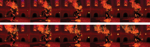
Figure 6-13 Weighting Particles for Believable Fire
Finding a fluid dynamics solution for the smoke motion would have been preferable. When the character moved, he would update a fluid dynamics solution that in return would affect the smoke motion. We spent a lot of effort exploring this possibility. In the end, fluid dynamics, by itself, was effective and could be fast, if not applied over a large area. We planned to do the simulation in the character's root local space and have the fluid solution "follow" him. Unfortunately, the small number of particles and their large size prevented us from taking advantage of the subtle motion created by fluid dynamics. In future projects that have more (and smaller) particles, we will revisit this solution.
6.4 Performance
Performance was the primary concern from the start. Using large, video-textured billboards consumed an enormous amount of pixel-processing power. As shown in Figure 6-14, the average size of a sprite was big compared to the screen. Obviously, we tried to set up the blending to get the alpha-test rejection for zero-alpha pixels (GeForce FX hardware does this automatically), but we were still left with millions of frame-buffer blending and texture operations per frame, which we reduced through the following methods.
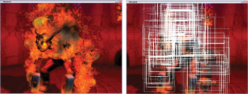
Figure 6-14 Sprite Size and Performance
6.4.1 Layer Composition
We found a solution by using layer composition. The flame source image was only 256x256, so we could afford to render it into a low-resolution buffer (a quarter of the screen resolution). This reduced the blending operations by a factor of four when we rendered the flames. See Figure 6-15.
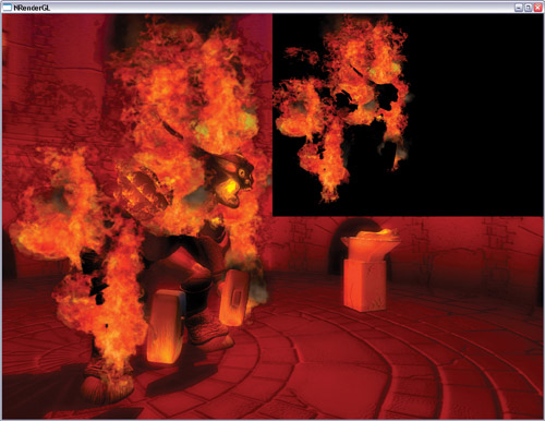
Figure 6-15 Using Layer Composition
The effect on the overall image quality was minimal, but the performance impact was huge. It was now possible to put the camera in the middle of the flames and yet have a good frame rate. See Figure 6-16.
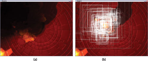
Figure 6-16 The Worst-Case Scenario with Sprites
6.4.2 Custom Sprites
As long as we were creating our own sprites, we decided that we might as well use them to enhance the performance. In the "Vulcan" demo, some particles were occupying down to one-third of the texture surface because of their square shape. In the end, it is wasteful to read all those unused texels, even if they're not blended to the frame buffer. Instead of doing square sprites, we could do rectangular sprites, which would be a better fit for some of the flames. Even better, we could do a pass that "analyzed" each frame, created the optimal rectangle to fit it, then added a 2D offset to center the sprite relative to the particle position. See Figure 6-17.
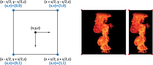
Figure 6-17 Generation Rules for DirectX 9 Point Sprites
6.5 Post-Rendering Effects
Using real-time compositing forced us to render the scene into a texture. We decided to turn this limitation into an advantage by adding post-rendering effects. We tried glow, film grain, and heat shimmer. Some effects didn't make it into the final demo because we preferred to shift pixel-processing power to other effects, such as the 2048x2048 shadow map. Conceptually, many 2D filters can be added as post-rendering effects at a linear cost, such as a color-correction matrix, as we did in our "Toys" demo.
Because we rendered the fire in a render target, we needed to z-test it against the character. Ideally we would have shared the depth buffer of the rendered scene with the fire rendering, but the render targets had different sizes, thus preventing depth-buffer sharing. As a fallback, we used a low-resolution model that we rendered into the depth buffer of the flames' render target. See Figure 6-18. It put a little bit of pressure on the vertex performance, but the savings in pixel processing justified it. In the end, only the glow effect is featured in the final demo, because it made the greatest visual contribution. See Figure 6-19.
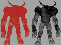
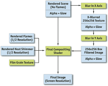
Figure 6-19 A Rendering Flowchart
6.5.1 Glow
We created glow by selectively adding a blurred version of the scene on top of the original one. The blur method was a two-pass box filter. In the first pass, we added an eight-pixel-wide blur on the x axis. Then we added an eight-pixel-wide blur on the y axis. We used the alpha channel of the blurred image to select which objects would be blurred.
See Figure 6-20, which illustrates the blurring and compositing process. Chapter 21 of this book, "Real-Time Glow," discusses this topic in much more detail.
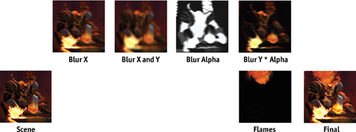
Figure 6-20 Images Computed During the Various Rendering Steps
6.5.2 Heat Shimmer
Although we had written all the code for heat shimmer, we decided in the end not to use it. The scene was too dark to make the effect interesting enough to spend the additional resources that would be needed.
Our heat shimmer was done in a straightforward way: We rendered a particle system of "heat" particles in a texture target. During the final compositing, we simply used the (red, green) values of each "heat render target" pixel as a (u, v) per-pixel 2D texture coordinates displacement during the texel fetch of the "rendered scene" texture target. That created a noise effect that looked like heat shimmer. See Figure 6-21.
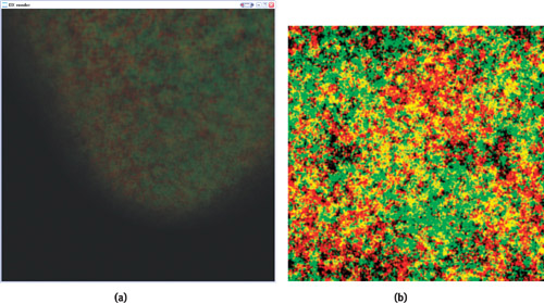
Figure 6-21 Heat Shimmer
Many game developers are using heat shimmering on a per-vertex basis, which also was a possibility for us. For example, it is possible to read from the same "heat render," and then use the values to perturb a tessellated 2D grid and deform the image. See Figure 6-22.
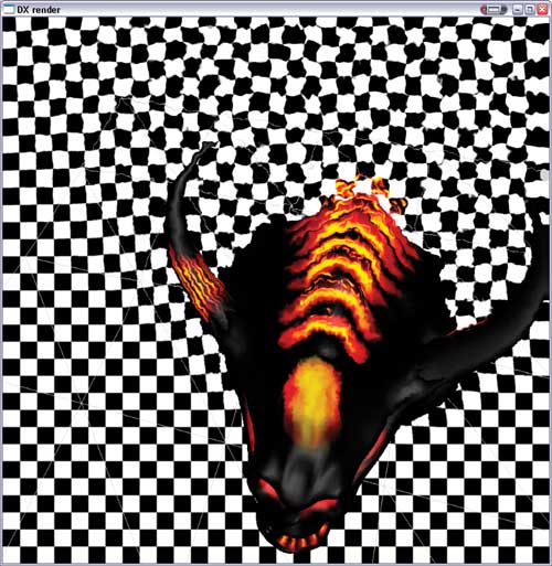
Figure 6-22 Per-Pixel Heat Shimmer During Development
6.5.3 Grain
Grain is often used in the movie industry to give computer-generated effects the same grain as the film. In our demo, we used grain to "soften" the rendering, and it worked. However, we worried that the audience might not like the grain or, worse, think of it as "jaggies," so we removed it. The grain texture was simply created using the Photoshop Noise filter. See Figures 6-23 and 6-24.
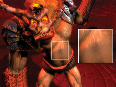
Figure 6-23 Zooming In on the Grain

Figure 6-24 The Texture Where the Grain Pattern Is Stored
6.5.4 The Final Program
Listing 6-1 shows the shader that brings together all the different layers to create the final image.
Example 6-1. The Final Shader
struct v2fConnector
{
  float2 tex1024x768 : TEXCOORD0;
  float2 colorTexGrain : TEXCOORD1;
  float2 tex256x192 : TEXCOORD2;
  float2 tex512x384 : TEXCOORD3;
  float2 texNormalized : TEXCOORD4;
};
struct f2fConnector
{
  float4 COL;
};
f2fConnector main(v2fConnector v2f, uniform texobjRECT renderedflames,
                  // "Flames"
                  uniformtexobjRECT renderedscene,
                  // "Scene"
                  uniformtexobj2D grain,
                  // "Grain"
                  uniformtexobjRECT heat,
                  // "Heat"
                  uniformtexobjRECT blur)
// "BlurY", "Blur Alpha"
{
  f2fConnector f2f;
  // Fetch heat distortion offset
  half4 HeatDistort = f4texRECT(heat, v2f.tex512x384) * float4(17, 23, 0, 1);
  // Fetch scene render using heat distortion
  half4 Scene = f4texRECT(renderedscene, v2f.tex1024x768 + HeatDistort.xy);
  // Fetch blurred version of the scene
  half4 BlurredScene = f4texRECT(blur, v2f.tex256x192);
  // Fetch flames and smoke
  half4 FlamesSmoke = f4texRECT(renderedflames, v2f.tex512x384);
  // Extract bright parts from blurred scene
  half4 Glow = BlurredScene * BlurredScene.a + Scene;
  // Compute final color output
  half4 Fcompoblur = lerp(Scene, BlurredScene, HeatDistort.a);
  half4 Fcomposited = lerp(Fcompoblur, FlamesSmoke, FlamesSmoke.a);
  f2f.COL = Fcomposited + Glow;
  return f2f;
}
6.6 Conclusion
In the end, we were able to achieve our goal of displaying some fairly realistic fire. Using video-based footage proved to be a good solution. Even though this technique is fairly memory intensive, it is scalable enough to be used on GPUs that have a small amount of memory. Fire effects will always be needed in many games, and we hope that this chapter inspires you to produce more advanced fire effects in your own applications.
Copyright
Many of the designations used by manufacturers and sellers to distinguish their products are claimed as trademarks. Where those designations appear in this book, and Addison-Wesley was aware of a trademark claim, the designations have been printed with initial capital letters or in all capitals.
The authors and publisher have taken care in the preparation of this book, but make no expressed or implied warranty of any kind and assume no responsibility for errors or omissions. No liability is assumed for incidental or consequential damages in connection with or arising out of the use of the information or programs contained herein.
The publisher offers discounts on this book when ordered in quantity for bulk purchases and special sales. For more information, please contact:
U.S. Corporate and Government Sales
(800) 382-3419
corpsales@pearsontechgroup.com
For sales outside of the U.S., please contact:
International Sales
international@pearsoned.com
Visit Addison-Wesley on the Web: www.awprofessional.com
Library of Congress Control Number: 2004100582
GeForce™ and NVIDIA Quadro® are trademarks or registered trademarks of NVIDIA Corporation.
RenderMan® is a registered trademark of Pixar Animation Studios.
"Shadow Map Antialiasing" © 2003 NVIDIA Corporation and Pixar Animation Studios.
"Cinematic Lighting" © 2003 Pixar Animation Studios.
Dawn images © 2002 NVIDIA Corporation. Vulcan images © 2003 NVIDIA Corporation.
Copyright © 2004 by NVIDIA Corporation.
All rights reserved. No part of this publication may be reproduced, stored in a retrieval system, or transmitted, in any form, or by any means, electronic, mechanical, photocopying, recording, or otherwise, without the prior consent of the publisher. Printed in the United States of America. Published simultaneously in Canada.
For information on obtaining permission for use of material from this work, please submit a written request to:
Pearson Education, Inc.
Rights and Contracts Department
One Lake Street
Upper Saddle River, NJ 07458
Text printed on recycled and acid-free paper.
5 6 7 8 9 10 QWT 09 08 07
5th Printing September 2007
- Contributors
- Copyright
- Foreword
- Part I: Natural Effects
-
- Chapter 1. Effective Water Simulation from Physical Models
- Chapter 2. Rendering Water Caustics
- Chapter 3. Skin in the "Dawn" Demo
- Chapter 4. Animation in the "Dawn" Demo
- Chapter 5. Implementing Improved Perlin Noise
- Chapter 6. Fire in the "Vulcan" Demo
- Chapter 7. Rendering Countless Blades of Waving Grass
- Chapter 8. Simulating Diffraction
- Part II: Lighting and Shadows
-
- Chapter 9. Efficient Shadow Volume Rendering
- Chapter 10. Cinematic Lighting
- Chapter 11. Shadow Map Antialiasing
- Chapter 12. Omnidirectional Shadow Mapping
- Chapter 13. Generating Soft Shadows Using Occlusion Interval Maps
- Chapter 14. Perspective Shadow Maps: Care and Feeding
- Chapter 15. Managing Visibility for Per-Pixel Lighting
- Part III: Materials
- Part IV: Image Processing
- Part V: Performance and Practicalities
-
- Chapter 28. Graphics Pipeline Performance
- Chapter 29. Efficient Occlusion Culling
- Chapter 30. The Design of FX Composer
- Chapter 31. Using FX Composer
- Chapter 32. An Introduction to Shader Interfaces
- Chapter 33. Converting Production RenderMan Shaders to Real-Time
- Chapter 34. Integrating Hardware Shading into Cinema 4D
- Chapter 35. Leveraging High-Quality Software Rendering Effects in Real-Time Applications
- Chapter 36. Integrating Shaders into Applications
- Part VI: Beyond Triangles
- Preface