
GPU Gems 3
GPU Gems 3 is now available for free online!
The CD content, including demos and content, is available on the web and for download.
You can also subscribe to our Developer News Feed to get notifications of new material on the site.
Chapter 11. Efficient and Robust Shadow Volumes Using Hierarchical Occlusion Culling and Geometry Shaders
Martin Stich
mental images
Carsten Wächter
Ulm University
Alexander Keller
Ulm University
11.1 Introduction
RealityServer is a mental images platform for creating and deploying 3D Web services and other applications (mental images 2007). The hardware renderer in RealityServer needs to be able to display a large variety of scenes with high performance and quality. An important aspect of achieving these kinds of convincing images is realistic shadow rendering.
RealityServer supports the two most common shadow-rendering techniques: shadow mapping and shadow volumes. Each method has its own advantages and drawbacks. It's relatively easy to create soft shadows when we use shadow maps, but the shadows suffer from aliasing problems, especially in large scenes. On the other hand, shadow volumes are rendered with pixel accuracy, but they have more difficulty handling light sources that are not perfect point lights or directional lights.
In this chapter, we explain how robust stencil shadow rendering is implemented in Reality-Server and how state-of-the-art hardware features are used to accelerate the technique.
11.2 An Overview of Shadow Volumes
The idea of rendering shadows with shadow volumes has been around for quite some time, but it became practical only relatively recently with the development of robust algorithms and enhanced graphics hardware support. We briefly explain the basic principles of the approach here; refer to McGuire et al. 2003, McGuire 2004, and Everitt and Kilgard 2002 for more-detailed descriptions.
11.2.1 Z-Pass and Z-Fail
Figure 11-1 shows the main idea behind shadow volumes. The actual shadow volume corresponds to the green area (all points behind the occluder that are not visible from the light source). Obviously, we would like to render all geometry that intersects the shadow volume without (or only with ambient) lighting, while everything outside the volume would receive the full contribution of the light source. Consider a ray with its origin at the camera cast toward the scene geometry, as shown in Figure 11-1a. We count the ray's intersections with the shadow volume, so that at each entry into the volume, a counter is increased and at each exit the counter is decreased. For the geometry parts in shadow (only), we end up with a value different from zero. That simple fact is the most important principle behind shadow volumes. If the counter value is available for each pixel, we have separated shadowed from nonshadowed areas and can easily use multipass rendering to exploit that information.
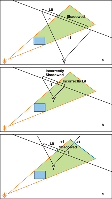
Figure 11-1 The Difference Between Z-Pass and Z-Fail
To obtain the counter values, we don't have to perform "real" ray tracing but can rely on the stencil functionality in any modern graphics hardware. First, we clear the stencil buffer by setting it to zero. Then, we render the boundary of the shadow volume into the stencil buffer (not into the color and depth buffer). We set up the hardware so that the value in the stencil buffer is increased on front-facing polygons and decreased on back-facing polygons. The increasing and the decreasing operations are both set to "wrap around," so decreasing zero and increasing the maximum stencil value do not result in saturation.
As a result of this pass, the stencil buffer will contain the intersection counter value for each pixel (which is zero for all nonshadowed pixels). On current graphics cards, volume rendering can be performed in a single render pass by using two-sided stencil writing, which is controlled in OpenGL with the glStencilOpSeparate() function. Before the shadow volumes are drawn, the z-buffer must be filled with the scene's depth values, which is usually the case because an ambient pass has to be rendered anyway.
Note that the stencil writes must be performed for every fragment for which the depth test passes. Hence, the method just described is called z-pass.
Z-pass is easy, but there is a problem with it. Take a look at Figure 11-1b. When the camera is inside a shadow volume, the algorithm yields the wrong results. Fortunately, a simple solution exists: Instead of counting the ray-volume intersections in front of the actual geometry, we can count the intersections behind it, as shown in Figure 11-1c. All we need to do is set up the graphics hardware to write to the stencil buffer if the depth test fails, and invert the increasing and decreasing operations. This method was discovered by John Carmack (2000) and is usually referred to as z-fail (or Carmack's reverse). Z-fail works for any case, but unlike z-pass, it must be assured that the volume caps are correctly rendered; that is, the volume must be closed both at its front end and at its back end. You can see in Figure 11-1c that a missing back cap would give the wrong results. For z-pass, the front cap does not need to be drawn because the depth test would fail, resulting in no stencil write anyway. The back cap can be omitted because it is placed at infinity behind all objects, so it would fail any depth test as well.
11.2.2 Volume Generation
The following approach is the most common way to generate shadow volumes. Note, however, that it works correctly only for closed two-manifold polygon meshes, meaning that objects cannot have holes, cracks, or self-intersections. We present a method that removes these restrictions in Section 11.3.
Rendering Steps
The actual rendering of the shadow volumes breaks down into these three steps:
- Rendering the front cap
- Rendering the back cap
- Rendering the object's extruded silhouette (the sides of the volume)
For the front cap, we loop over all the polygons in the model and render the ones that face the light. Whether a polygon faces the light or not can be checked efficiently by testing the sign of the dot product between the face normal and the direction to the light. For the back cap, we render the same polygons again, with all the vertices projected to infinity in the direction of the light. This projection method is also used for the volume sides, where we draw the possible silhouette edges extruded to infinity, resulting in quads. The possible silhouette edges (the edges that may be part of the actual occluder silhouette) are found by comparing the signs of the dot products between the surface normal and the direction to the light with those of the neighboring faces. If the signs differ, the edge is extruded. For nonconvex objects, this extrusion can result in nested silhouettes, which do not break shadow rendering. Yet it is important that in all cases, the generated faces are oriented so that their normal points outside the shadow volume; otherwise, the values in the stencil buffer will get out of balance.
Rendering at Infinity
How are all these vertices at infinity actually handled? Rendering at infinity is intrinsic to homogeneous coordinates in OpenGL (and Direct3D as well). A vertex can be rendered as if it were projected onto an infinitely large sphere by passing a direction instead of a position. In our case, this direction is the vector from the light position toward the vertex. In homogeneous coordinates, directions are specified by setting the w component to zero, whereas positions usually have w set to one.
When rendering at infinity, we run into the problem that primitives will be clipped against the far plane. A convenient way to counteract this clipping is to use depth clamping, which is supported by the NV_depth_clamp extension in OpenGL. When enabled, geometry is rendered even behind the far plane and produces the maximum possible depth value there. If the extension is not available, a special projection matrix can be used to achieve the same effect, as described in Everitt and Kilgard 2002.
11.2.3 Performance and Optimizations
For reasonably complex scenes, shadow volumes can cost a lot of performance. Thus, many optimizations have been developed, some of which we discuss briefly here. The first important observation is that z-pass usually performs faster than z-fail, mainly because we don't have to render the volume caps. In addition, the occluded part of the shadow volume is usually larger on screen than the unoccluded part, which makes z-fail consume more fill rate. It therefore makes sense to use z-pass whenever possible and switch to z-fail only when necessary (when the camera is inside the shadow volume).
Z-pass and z-fail can be used simultaneously in a render pass, and it pays off to dynamically switch between the two, requiring only a (conservative) test whether the camera is inside a volume. Fill rate is often the main bottleneck for shadow volumes, so further optimizations that have been proposed include volume culling, limiting volumes using the scissor test, and depth bounds (see McGuire et al. 2003 for more information on these methods).
11.3 Our Implementation
Now that we have discussed the basics of shadow volumes, let's take a look at some methods to improve robustness and performance. This section shows you some of the approaches we have taken at mental images to make shadow volumes meet the requirements of RealityServer.
11.3.1 Robust Shadows for Low-Quality Meshes
Traditionally, shadow volume algorithms are used in applications such as games, where the artist has full control over the meshes the game engine has to process. Hence, it is often possible to constrain occluders to be two-manifold meshes, which simplifies shadow volume generation. However, RealityServer needs to be able to correctly handle meshes of low quality, such as meshes that are not closed or that have intersecting geometry. These kinds of meshes are often generated by CAD software or conversion tools. We would therefore like to lower the constraints on meshes for which artifact-free shadows are rendered, without sacrificing too much performance.
A Modified Volume Generation Algorithm
The method we implemented is a small modification to the volume generation algorithm described in Section 11.2.2. In that approach, in addition to drawing the caps, we simply extruded an edge of a polygon facing the light whenever its corresponding neighbor polygon did not face the light.
Now, to work robustly for non-two-manifolds, the algorithm needs to be extended in two ways:
- First, we also extrude edges that do not have any neighbor polygons at all. This is an obvious extension needed for nonclosed meshes (imagine just a single triangle as an occluder, for example).
- Second, we take into account all the polygons in a mesh, not only the ones facing the light, to extrude possible silhouette edges and to draw the caps. This means that all silhouette edges that have a neighbor polygon are actually extruded twice, once for each connected polygon.
Now why does this make sense? Take a look at Figure 11-2. The shadow volume for this open mesh is rendered correctly, because the two highlighted edges are extruded twice. The resulting sides close the shadow volumes of both the light-facing and the nonlight-facing polygon sets.
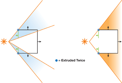
Figure 11-2 Dividing an Object into Multiple Parts
In fact, the algorithm can now be seen as a method that divides an object into multiple parts, with each part consisting of only front-facing or back-facing polygons with respect to the light source. Then for each part, the corresponding shadow volume is rendered, similar to multiple separate objects behind each other. This technique even works for self-intersecting objects. As before, we have to pay careful attention that all shadow volume geometry is oriented correctly (with the normal pointing out of the volume). Now that we also consider polygons not facing the light, we have to invert all the generated volume faces on these polygons.
Performance Costs
The new approach is simple and effective, but it comes at a cost. If, for example, we are rendering a two-manifold mesh, we are doing twice the work of the nonrobust algorithm. For z-fail, the caps are rendered twice instead of once (for the front and the back faces), and all the possible silhouette edges are extruded twice as well. However, the caps are not too much of a problem, because for most scenes, only a few occluders will need to be handled with z-fail. Remember that for z-pass, we don't have to draw any caps at all.
A bigger issue is that there is twice the number of extruded silhouette edges. One simple solution would be to extrude and render edges connected to two faces only once, and increase or decrease the value in the stencil buffer by 2 instead of 1. For z-pass, this would bring down the cost of the algorithm to be the same as for the nonrobust method! However, this functionality is not supported in graphics hardware, so we cannot get around rendering those edges twice. To minimize the unavoidable performance loss, our implementation detects if a mesh is two-manifold in a preprocessing step and employs the robust volume generation only if necessary.
Also, note that there are still cases that are not handled by our implementation: in particular, more than two polygons sharing an edge, and polygons that share an edge but have different vertex winding order. This, as well, is handled during preprocessing, where such cases are converted into single, disconnected polygons.
Even though dealing with difficult meshes in combination with shadow volumes sounds tricky at first, it should be extremely easy to integrate the presented method into any existing stencil shadow system. For RealityServer, robust shadows are a must—even if they come at the cost of some performance—because it's usually impossible to correct the meshes the application has to handle.
11.3.2 Dynamic Volume Generation with Geometry Shaders
NVIDIA's GeForce 8 class hardware enables programmable primitive creation on the GPU in a new pipeline stage called the geometry shader (GS). Geometry shaders operate on primitives and are logically placed between the vertex shader (VS) and the fragment shader (FS). The vertices of an entire primitive are available as input parameters. A detailed description can be found in NVIDIA Corporation 2007.
It is obvious that this new capability is ideally suited for the dynamic creation of shadow volumes. Silhouette determination is not a cheap task and must be redone every frame for animated scenes, so it is preferable to move the computational load from the CPU to the GPU. Previous approaches to creating shadow volumes entirely on the GPU required fancy tricks with vertex and fragment shaders (Brabec and Seidel 2003). Now, geometry shaders provide a "natural" solution to this problem. A trivial GS reproducing the fixed-function pipeline would just take the input primitive and emit it again, in our case generating the front cap of a shadow volume. We will be creating additional primitives for the back cap and extruded silhouette edges, as needed. The exact same robust algorithm as described in Section 11.3.1 can be implemented entirely on the GPU, leading to a very elegant way of creating dynamic shadows.
To compute the silhouette edges of a mesh, the geometry shader has to have access to adjacency information of triangles. In OpenGL, we can pass in additional vertices per triangle using the new GL_TRIANGLES_ADJACENCY_EXT mode for glBegin. In this mode we need six, instead of three, vertices to complete a triangle, three of which specify the neighbor vertices of the edges. Figure 11-3 illustrates the vertex layout of a triangle with neighbors.
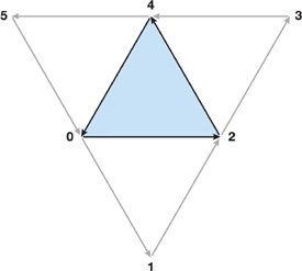
Figure 11-3 Input Vertices for a Geometry Shader
In addition to specifying the input primitive type, we need to specify the type of primitives a GS will create. We choose triangle strips, which lets us efficiently render single triangles (for the caps), as well as quads (for the extruded silhouette edges). The maximum allowed number of emitted vertices will be set to 18 (3 + 3 for the two caps plus 4 x 3 for the sides).
Listing 11-1 shows the GLSL implementation of the geometry shader. The code assumes that gl_PositionIn contains the coordinates of the vertices transformed to eye space. This transformation is done in the VS simply by multiplying the input vertex with gl_ModelViewMatrix and writing it to gl_Position. All the vertices of a primitive will then show up in the gl_PositionIn array. If an edge does not have a neighbor triangle, we encode this by setting w to zero for the corresponding adjacency vertex.
Example 11-1. A GLSL Implementation of the Volume Generation Geometry Shader
#version 120
#extension GL_EXT_geometry_shader4: enable
   uniform vec4 l_pos;  // Light position (eye space)
   uniform int robust;  // Robust generation needed?
   uniform int zpass;  // Is it safe to do z-pass?
   void main()
{
   vec3 ns[3];  // Normals
   vec3 d[3];  // Directions toward light
   vec4 v[4];  // Temporary vertices
   vec4 or_pos[3] = {  // Triangle oriented toward light source
     gl_PositionIn[0],
     gl_PositionIn[2],
     gl_PositionIn[4]
   };
   // Compute normal at each vertex.
   ns[0] = cross(
     gl_PositionIn[2].xyz - gl_PositionIn[0].xyz,
     gl_PositionIn[4].xyz - gl_PositionIn[0].xyz );
   ns[1] = cross(
     gl_PositionIn[4].xyz - gl_PositionIn[2].xyz,
     gl_PositionIn[0].xyz - gl_PositionIn[2].xyz );
   ns[2] = cross(
     gl_PositionIn[0].xyz - gl_PositionIn[4].xyz,
     gl_PositionIn[2].xyz - gl_PositionIn[4].xyz );
   // Compute direction from vertices to light.
   d[0] = l_pos.xyz-l_pos.w*gl_PositionIn[0].xyz;
   d[1] = l_pos.xyz-l_pos.w*gl_PositionIn[2].xyz;
   d[2] = l_pos.xyz-l_pos.w*gl_PositionIn[4].xyz;
   // Check if the main triangle faces the light.
   bool faces_light = true;
   if ( !(dot(ns[0],d[0])>0 || dot(ns[1],d[1])>0 ||
          dot(ns[2],d[2])>0) ) {
     // Not facing the light and not robust, ignore.
   if ( robust == 0 ) return;
     // Flip vertex winding order in or_pos.
     or_pos[1] = gl_PositionIn[4];
     or_pos[2] = gl_PositionIn[2];
     faces_light = false;
  }
  // Render caps. This is only needed for z-fail.
   if ( zpass == 0 ) {
     // Near cap: simply render triangle.
     gl_Position = gl_ProjectionMatrix*or_pos[0];
     EmitVertex();
     gl_Position = gl_ProjectionMatrix*or_pos[1];
     EmitVertex();
     gl_Position = gl_ProjectionMatrix*or_pos[2];
     EmitVertex(); EndPrimitive();
     // Far cap: extrude positions to infinity.
     v[0] =vec4(l_pos.w*or_pos[0].xyz-l_pos.xyz,0);
     v[1] =vec4(l_pos.w*or_pos[2].xyz-l_pos.xyz,0);
     v[2] =vec4(l_pos.w*or_pos[1].xyz-l_pos.xyz,0);
     gl_Position = gl_ProjectionMatrix*v[0];
     EmitVertex();
     gl_Position = gl_ProjectionMatrix*v[1];
     EmitVertex();
     gl_Position = gl_ProjectionMatrix*v[2];
     EmitVertex(); EndPrimitive();
  }
  // Loop over all edges and extrude if needed.
   for ( int i=0; i<3; i++ ) {
     // Compute indices of neighbor triangle.
   int v0 = i*2;
     int nb = (i*2+1);
     int v1 = (i*2+2) % 6;
     // Compute normals at vertices, the *exact*
   // same way as done above!
     ns[0] = cross(
       gl_PositionIn[nb].xyz-gl_PositionIn[v0].xyz,
       gl_PositionIn[v1].xyz-gl_PositionIn[v0].xyz);
     ns[1] = cross(
       gl_PositionIn[v1].xyz-gl_PositionIn[nb].xyz,
       gl_PositionIn[v0].xyz-gl_PositionIn[nb].xyz);
     ns[2] = cross(
       gl_PositionIn[v0].xyz-gl_PositionIn[v1].xyz,
       gl_PositionIn[nb].xyz-gl_PositionIn[v1].xyz);
     // Compute direction to light, again as above.
     d[0] =l_pos.xyz-l_pos.w*gl_PositionIn[v0].xyz;
     d[1] =l_pos.xyz-l_pos.w*gl_PositionIn[nb].xyz;
     d[2] =l_pos.xyz-l_pos.w*gl_PositionIn[v1].xyz;
     // Extrude the edge if it does not have a
   // neighbor, or if it's a possible silhouette.
   if ( gl_PositionIn[nb].w < 1e-3 ||
          ( faces_light != (dot(ns[0],d[0])>0 ||
                            dot(ns[1],d[1])>0 ||
                            dot(ns[2],d[2])>0) ))
     {
       // Make sure sides are oriented correctly.
   int i0 = faces_light ? v0 : v1;
       int i1 = faces_light ? v1 : v0;
       v[0] = gl_PositionIn[i0];
       v[1] = vec4(l_pos.w*gl_PositionIn[i0].xyz - l_pos.xyz, 0);
       v[2] = gl_PositionIn[i1];
       v[3] = vec4(l_pos.w*gl_PositionIn[i1].xyz - l_pos.xyz, 0);
       // Emit a quad as a triangle strip.
       gl_Position = gl_ProjectionMatrix*v[0];
       EmitVertex();
       gl_Position = gl_ProjectionMatrix*v[1];
       EmitVertex();
       gl_Position = gl_ProjectionMatrix*v[2];
       EmitVertex();
       gl_Position = gl_ProjectionMatrix*v[3];
       EmitVertex(); EndPrimitive();
     }
  }
}
One thing to take care of at this point is to transform the actual rendered scene geometry exactly like the geometry in the shadow volume shader. That is, if you use ftransform or the fixed-function pipeline for rendering, you will probably have to adjust the implementation so that at least the front caps use coordinates transformed with ftransform as well. Otherwise, you are likely to get shadow artifacts ("shadow acne") caused by z-fighting. The parameter l_pos contains the light position in eye space, in 4D homogeneous coordinates. This makes it easy to pass in point lights and directional lights without having to handle each case separately.
The uniform variable robust controls whether or not we need to generate volumes with the algorithm from Section 11.3.1. If we know a mesh is a two-manifold, robust can be set to false, in which case the shader simply ignores all polygons not facing the light. This means we effectively switch to the well-known volume generation method described in Section 11.2.2. The zpass flag specifies whether we can safely use the z-pass method. This decision is determined at runtime by checking if the camera is inside the shadow volume. (In fact, we check conservatively by using a coarser bounding volume than the exact shadow volume.) If so, z-fail needs to be used; otherwise, the shader can skip rendering the front and back caps.
Note that the code also takes care of an issue that we have not discussed yet, but frequently arises with low-quality meshes: degenerate triangles. A triangle can either be degenerate from the beginning or become degenerate when being transformed to eye space, due to numerical inaccuracies in the computations. Often, this happens with meshes that have been tessellated to polygons and contain very small or very thin triangles. Degenerate (or nearly degenerate) triangles are an ugly problem in shadow volume generation because the artifacts they cause are typically not only visible in the shadow itself, but also show up as shadow streaks "leaking" out of the occluder.
The main difficulty with degenerate triangles is to decide whether or not they face the light. Depending on how we compute the normal that is later compared to the light direction, we may come to different conclusions. We then run into trouble if, as in a geometry shader, we need to look at the same triangle multiple times (what is our "main" triangle at one point can be a "neighbor" triangle at another point). If two such runs don't yield the same result, we may have one extruded silhouette too many, or one too few, which causes the artifacts.
To handle this problem, we make sure we perform exactly the same computations whenever we need to decide whether a triangle faces the light or not. Unfortunately, this solution leads to computing three normals per triangle and comparing them to three different light direction vectors. This operation, of course, costs some precious performance, so you might go back to a less solid implementation if you know you will be handling only meshes without "difficult" triangles.
11.3.3 Improving Performance with Hierarchical Occlusion Culling
Shadow volumes were integrated into RealityServer mainly for use in large scenes, such as city models, where shadow maps typically do not perform well. In such scenes, we can increase rendering performance dramatically by using a hierarchical occlusion culling method, such as the one presented in Wimmer and Bittner 2005. A description of this approach is also available online (Bittner et al. 2004).
The idea is to organize all objects in the scene in a hierarchical tree structure. During rendering, the tree is recursively traversed in a front-to-back order, and the objects contained in the leaf nodes are rendered. Before a tree node is traversed, however, it is tested for visibility using the occlusion culling feature provided by the graphics hardware. If the node is found to be invisible, the entire subtree can be pruned. The simplest hierarchical structure to use in this case is a binary bounding-volume hierarchy (BVH) of axis-aligned bounding boxes (AABBs). This kind of hierarchy is extremely fast to generate, which is important for animated scenes, where the BVH (or parts of it) needs to be rebuilt every frame.
To check whether a node is visible, we can first test it against intersection with the viewing frustum and then perform an occlusion query simply by rendering the AABB. Only if it is actually visible do we continue tree traversal or render the leaf content, respectively.
To optimally exploit the hierarchical occlusion culling technique, we should make use of asynchronous occlusion queries and temporal coherence, as described by Wimmer and Bittner 2005. Because occlusion queries require a readback from the GPU, they have a relatively large overhead. Thus, we can issue an asynchronous occlusion query and continue traversal at some other point in the tree until the query result is available. Storing information about whether or not a node was visible in the previous frame helps estimate whether an occlusion query is required at all, or whether it may be faster to just traverse the node without a query.
We now extend this idea to shadow volumes as well. We would like to find out if we can skip a certain node in the tree because we know that no object in this part of the hierarchy will cast a visible shadow. Instead of testing the bounding box of the node with an occlusion query, we test the bounding box extruded in the light direction, as if the AABB itself would cast a shadow. In other words, we effectively perform occlusion culling on the shadow volumes of the node bounding boxes. If this extruded box is not visible, it means that any shadow cast by an object inside the bounding box cannot be visible, and the node can be disregarded. The principle is shown in Figure 11-4. Two occluders, for which shadow volume rendering is potentially expensive, are contained in a BVH. The shadow volume of the AABB of the blue object is occluded by the orange object and thus is not visible to the camera, so we can safely skip generating and rendering the actual shadow volume of the blue object.
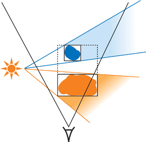
Figure 11-4 Two Occluders in a BVH
This conclusion is, of course, also true if the occluded node holds an entire subtree of the scene instead of just one object. When the tree traversal reaches a visible leaf node, its shadow volume is rendered using the methods described earlier in this chapter. Note that we need to give special attention to cases of the light source being inside the currently processed AABB or of the camera being inside the extruded AABB. It is, however, quite simple to detect these cases, and we can then just traverse the node without performing an occlusion query.
Obviously, the same optimizations as used for conventional hierarchical occlusion culling can also be used for the extended method. Asynchronous occlusion queries and temporal coherence work as expected. The only difference is that, in order to take into account temporal coherence, we must include the coherency information per light source in each BVH node. That is, for each light and node, we store a visibility flag (whether or not a node's shadow volume was visible the last time it was checked), along with a frame ID (describing when the visibility information was last updated).
The hierarchical culling method described here does not increase performance in all cases. In fact, in some situations, rendering may even be slightly slower compared to simply drawing all the objects in the scene. However, for the majority of our scenes, hierarchical culling (both the original and the shadow volume variant) improves performance considerably. In cases such as a city walkthrough, this speedup is often dramatic.
11.4 Conclusion
We achieve very robust rendering of shadows, even for difficult meshes, by employing a nonstandard method for generating shadow volume geometry. By using this method in combination with hierarchical hardware occlusion queries and geometry shaders, we also achieve high performance for situations that previously did not work well with stencil shadows. Examples can be seen in Figures 11-5 and 11-6. All the presented techniques are relatively straightforward to implement.
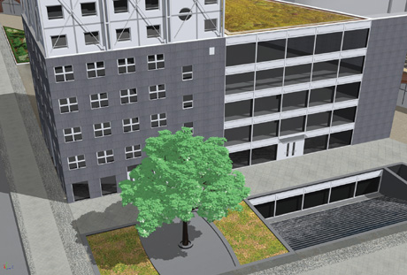
Figure 11-5 A City Scene Close-up Containing a Complex Tree Mesh with Roughly Half a Million Polygons
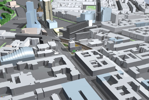
Figure 11-6 The Same Model as in , Zoomed Out
In the future, we will investigate additional performance optimizations, especially for handling scenes with extremely high geometric complexity.
11.5 References
Bittner, J., M. Wimmer, H. Piringer, and W. Purgathofer. 2004. "Coherent Hierarchical Culling: Hardware Occlusion Queries Made Useful." In Computer Graphics Forum (Proceedings of Eurographics 2004) 23(3), pp. 615–624.
Brabec, S., and H. Seidel. 2003. "Shadow Volumes on Programmable Graphics Hardware." In Computer Graphics Forum (Proceedings of Eurographics 2003) 25(3).
Carmack, John. 2000. Personal communication. Available online at http://developer.nvidia.com/object/robust_shadow_volumes.html.
Everitt, Cass, and Mark Kilgard. 2002. "Practical and Robust Stenciled Shadow Volumes for Hardware-Accelerated Rendering." Available online at http://developer.nvidia.com/object/robust_shadow_volumes.html.
McGuire, Morgan. 2004. "Efficient Shadow Volume Rendering." In GPU Gems, edited by Randima Fernando, pp. 137–166. Addison-Wesley.
McGuire, Morgan, John F. Hughes, Kevin Egan, Mark Kilgard, and Cass Everitt. 2003. "Fast, Practical and Robust Shadows." Brown Univ. Tech. Report CS03-19. Oct. 27, 2003. Available online at http://developer.nvidia.com/object/fast_shadow_volumes.html. mental images. 2007. "RealityServer Functional Overview." White paper. Available online at http://www.mentalimages.com/2_3_realityserver/index.html.
NVIDIA Corporation. 2007. "NVIDIA OpenGL Extension Specifications." Available online at http://developer.nvidia.com/object/nvidia_opengl_specs.html.
Wimmer, Michael, and Jiri Bittner. 2005. "Hardware Occlusion Queries Made Useful." In GPU Gems 2, edited by Matt Pharr, pp. 91–108. Addison-Wesley.
- Contributors
- Foreword
- Part I: Geometry
-
- Chapter 1. Generating Complex Procedural Terrains Using the GPU
- Chapter 2. Animated Crowd Rendering
- Chapter 3. DirectX 10 Blend Shapes: Breaking the Limits
- Chapter 4. Next-Generation SpeedTree Rendering
- Chapter 5. Generic Adaptive Mesh Refinement
- Chapter 6. GPU-Generated Procedural Wind Animations for Trees
- Chapter 7. Point-Based Visualization of Metaballs on a GPU
- Part II: Light and Shadows
-
- Chapter 8. Summed-Area Variance Shadow Maps
- Chapter 9. Interactive Cinematic Relighting with Global Illumination
- Chapter 10. Parallel-Split Shadow Maps on Programmable GPUs
- Chapter 11. Efficient and Robust Shadow Volumes Using Hierarchical Occlusion Culling and Geometry Shaders
- Chapter 12. High-Quality Ambient Occlusion
- Chapter 13. Volumetric Light Scattering as a Post-Process
- Part III: Rendering
-
- Chapter 14. Advanced Techniques for Realistic Real-Time Skin Rendering
- Chapter 15. Playable Universal Capture
- Chapter 16. Vegetation Procedural Animation and Shading in Crysis
- Chapter 17. Robust Multiple Specular Reflections and Refractions
- Chapter 18. Relaxed Cone Stepping for Relief Mapping
- Chapter 19. Deferred Shading in Tabula Rasa
- Chapter 20. GPU-Based Importance Sampling
- Part IV: Image Effects
-
- Chapter 21. True Impostors
- Chapter 22. Baking Normal Maps on the GPU
- Chapter 23. High-Speed, Off-Screen Particles
- Chapter 24. The Importance of Being Linear
- Chapter 25. Rendering Vector Art on the GPU
- Chapter 26. Object Detection by Color: Using the GPU for Real-Time Video Image Processing
- Chapter 27. Motion Blur as a Post-Processing Effect
- Chapter 28. Practical Post-Process Depth of Field
- Part V: Physics Simulation
-
- Chapter 29. Real-Time Rigid Body Simulation on GPUs
- Chapter 30. Real-Time Simulation and Rendering of 3D Fluids
- Chapter 31. Fast N-Body Simulation with CUDA
- Chapter 32. Broad-Phase Collision Detection with CUDA
- Chapter 33. LCP Algorithms for Collision Detection Using CUDA
- Chapter 34. Signed Distance Fields Using Single-Pass GPU Scan Conversion of Tetrahedra
- Chapter 35. Fast Virus Signature Matching on the GPU
- Part VI: GPU Computing
-
- Chapter 36. AES Encryption and Decryption on the GPU
- Chapter 37. Efficient Random Number Generation and Application Using CUDA
- Chapter 38. Imaging Earth's Subsurface Using CUDA
- Chapter 39. Parallel Prefix Sum (Scan) with CUDA
- Chapter 40. Incremental Computation of the Gaussian
- Chapter 41. Using the Geometry Shader for Compact and Variable-Length GPU Feedback
- Preface