GPU Gems 3
GPU Gems 3 is now available for free online!
The CD content, including demos and content, is available on the web and for download.
You can also subscribe to our Developer News Feed to get notifications of new material on the site.
Chapter 41. Using the Geometry Shader for Compact and Variable-Length GPU Feedback
Franck Diard
NVIDIA Corporation
41.1 Introduction
Although modern graphics hardware is designed for high-performance computer graphics, the GPU is being increasingly used in other domains, such as image processing and technical computing, to take advantage of its massively parallel architecture.
Several generations of GPUs have incrementally delivered better instruction sets with branching and texture fetches for fragment programs, making the GPU a fantastic machine to execute data-parallel algorithms. On the other hand, algorithms with dynamic output such as compression or data searching are not well mapped to the GPU.
With a high-level shading language like Cg, programming the GPU is now very easy. However, GPU shader programs run in very constrained contexts: vertex shading and pixel shading. These execution environments are designed for performance and are not very helpful for more conventional serial or dynamic programming.
In this chapter, we demonstrate how to use the geometry shader (GS) unit of Microsoft's DirectX 10 (DX10)-compliant graphics hardware (Microsoft 2007) to implement some algorithms with variable input and output on the GPU. Introduced as an extra stage between vertex processing and fragment processing, the geometry shader adds or deletes some elements in the geometry stream sent to the rendering pipeline. However, by using this unit in a way that differs from its original purpose, we can exploit the GPU to implement a broad class of general-purpose algorithms beyond the normal usage of processing geometry.
41.2 Why Use the Geometry Shader?
The geometry shader is unique because it can be programmed to accomplish some tasks that neither the vertex shader (VS) nor the pixel shader (PS) units can perform efficiently. This capability allows a new class of commodity algorithms to be performed on the GPU. For example, in the computer vision domain, this new programming technique can be used to avoid reading back images on the GPU. By sending back only a few scalars to system memory, the GS can increase throughput and scalability.
Suppose we would like to write some shading code executed by the GPU that scans a texture input and writes a number 2n + 1 of real numbers in the frame buffer, where n is computed dynamically while reading the contents of the input texture. The algorithm output is a set of 2D locations—pairs of x and y scalars—in addition to the number of pairs as a scalar.
This output cannot be implemented with a pixel shader for two reasons:
- A pixel shader repeats the same algorithm for all the pixels of the output buffer, and this size is not known in advance.
- A fragment processor working on a pixel from the output buffer has no visibility to the context of other threads that are processing other pixels (adjacent or not), so no global/adaptive decision can be taken.
Vertex shaders are also not very helpful for this kind of algorithm. Let's take a compressor program, for example, that is working on an input stream of data. By sending one geometry primitive (such as a flat triangle), the vertex program can loop over the input data and compress. However, the program will have to pass exactly one triangle to the rasterizer to write different bytes (the compressed codes) to the output buffer. This is not possible, because the program will write the same code to all the pixels rasterized by the geometry element.
So although a vertex shader can run a program that collects statistics on the input data by fetching texels, it has only two options:
- It can kill the primitive (which is useless).
- It can forward down the pipeline a primitive for which rasterization will write the same code on all corresponding pixels. To be able to write n different codes to the output buffer, the VS would have to receive n elements of geometry. But then n vertex shader programs would run, all doing the same thing and unable to make any adaptive decisions because they run in separate GPU threads, isolated from each other.
41.3 Dynamic Output with the Geometry Shader
The geometry shader, in contrast to the fragment or vertex shader, is able to output variable-length results based on adaptive, data-dependent execution. In a single pass, the GS can analyze input data (for example, the contents of a texture) and output a variable-length code (many scalars can be emitted by a single GS thread). In this way, the GS unit is able to implement small algorithms for which the following is true:
- The output size is not known in advance.
- The output size is known, but the size spans several pixels.
It's possible to execute these algorithms by sending a single vertex to the GS. If some input data can be passed in as static Cg program parameters in the color, this vertex is processed in a single GPU thread. This thread can build statistics, fetch as many texels as needed, perform math operations, plus write a variable-length output by emitting an adaptive number of scalars.
The GS unit can write its results in two ways:
- By emitting vertices for which the rasterizer will write the scalar values at any location in the render target.
- By emitting scalars that are incrementally added to a stream-out buffer, a DX10 feature that redirects the output of the GS unit into a 1D buffer in GPU-accessible memory. (For more information, refer to the DX10 specification [Microsoft 2007].)
The geometry shader is able to write arbitrary blobs to an output buffer at any location (1D or 2D) and at any rate (the number of scalar outputs per input vertex) by passing data packets to the rasterizer. In Figure 41-1, the GS emits and transmits vertices down the rendering pipeline as the GS program progresses. The 2D coordinates are set by the GS program, which keeps incrementing the x coordinate each time it emits values to be written.
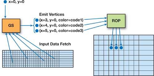
Figure 41-1 A Single Vertex Sent to the GS Emits Several Vertices
If the output of the program is sent to the frame buffer, these few bytes of output can be read back with the glReadPixels() function. If the render target is in system memory, the rasterizer will write only a few bytes to system memory, where the CPU can retrieve the bits directly. This approach provides good bus optimization compared to moving the whole input data to system memory for the CPU to analyze.
The "position" and "color" (a packet of scalars) of these emitted vertices are computed by the GS program and given to the rasterizer. The x and y coordinates of the vertices tell the rasterizer where to write the scalars that are stored in the frame buffer's color packet. For this to work, the codes emitted by the GS have to be untouched by the transform and clipping unit, so the model/view transforms are set to "identity," with no filtering, pixel shader usage, or lighting effects allowed.
The stream-out feature of DX-compliant hardware can also be used for output. In this case, the GS program does not have to track the 2D location of the pixels being output. The stream-out feature is compact because it does not use the "location" components; however, this feature may be less convenient because it is only an incremental output in a linear buffer. This stream-out buffer also needs to be changed for each GS thread, which is not efficient when we expect several GS threads to execute in parallel. If the stream-out's output is stored directly at some 2D position in the frame buffer, it can be readily used as an input texture to the next processing stage, which is useful when we're implementing on-the-fly texture compression.
If the CPU needs to retrieve the number of codes that were output, it can read the quantity from a known position in the output data, such as the first scalar written at the end of the GS thread when the exact number of emitted codes is known. Or, it can retrieve the quantity through an occlusion query.
41.4 Algorithms and Applications
41.4.1 Building Histograms
Building fast histograms efficiently is useful in many image-processing algorithms, including contrast correction and tone-mapping high-dynamic-range (HDR) images. The output of a histogram computation is a fixed-size data set, where the size typically matches the range of the input. For example, the histogram of an 8-bit-luminance image is an array of 256 scalar values. The size of the output would preclude an implementation through a pixel shader program because the output would span several pixels. The GS implementation, like the one shown in Listing 41-1, is simply done using a Cg program (version 2.0).
Example 41-1. Building a Histogram in a Geometry Shader
POINT void histoGS( AttribArray<float4> position : POSITION,
                    AttribArray<float4> color : COLOR,
                    uniform samplerRECT texIn)
{
  float h[256], lum, i, j;
  float3 c;
  for (int j=0; j<256; j++) h[j] = 0; //Histogram init
   float sx=color[0].x, sy=color[0].y; //Read block size from
   //vertex color.
   // Compute the luminance value for this pixel.
  c.x=255.0*0.30; c.y=255.0*0.59; c.z=255.0*0.11;
  for (j=0; j<sy; j++)
    for (i=0; i<sx;  i++)
    {
      lum=dot(texRECT(texIn, float2(i, j)).xyz, c.xyz);
      h[lum]++;
    }
  // Write the histogram out.
   float4 outputPos : POSITION = position[0];
  outputPos.x=0; outputPos.y=0;
  for (int j=0; j<64; j++)
  {
    outputPos.x = -1 + j/128.0;  // Moving the output pixel
    emitVertex(outputPos, float4(h[j*4], h[j*4+1],
               h[j*4+2], h[j*4+3]) : COLOR);
  }
}
As we can see in Listing 41-1, the GS will build this histogram in one pass and output the results in the floating-point render target (type GL_FLOAT_RGBA_NV). Also, the GS keeps track of the x coordinate of the emitted pixels.
The trigger in this case is a simple OpenGL program, which needs some special setup because what we pass in as colors are just full-range floating-point numbers in and out of shading programs, as shown in Listing 41-2.
Example 41-2. OpenGL Setup to Avoid Clamping
glClampColorARB(GL_CLAMP_VERTEX_COLOR_ARB, FALSE);
glClampColorARB(GL_CLAMP_FRAGMENT_COLOR_ARB, FALSE);
glClampColorARB(GL_CLAMP_READ_COLOR_ARB, FALSE);
It's possible to send only one vertex to produce a GS thread that can read the entire input image and output the histogram values in one pass. However, the GPU is inherently parallel, so we can increase performance if we execute this histogram computation on several GS threads, with each thread working on a partition of the input image. This technique is easily performed by sending several vertices to trigger more GS threads.
The color of each vertex contains the coordinates and bounds of the input area. Each GS thread can be programmed to output its histogram to n different locations in the frame buffer (256 scalars = 64 RGBA32F pixels each). The outputs can then be read back on the CPU (n x 256 floats) and summed. There is, however, room for a little optimization. Because the output histogram bins are simply added together, we can program the n threads to output their results in the same frame-buffer location and enable the GL_BLEND function with GL_ONE/GL_ONE as arguments. This way, the floating-point values are summed up automatically and only one vector of 256 floats needs to be read back to the CPU.
Figure 41-2 illustrates a GS histogram algorithm using multiple threads, where each thread handles a separate partition of the input image and all the threads write results to the same output array.
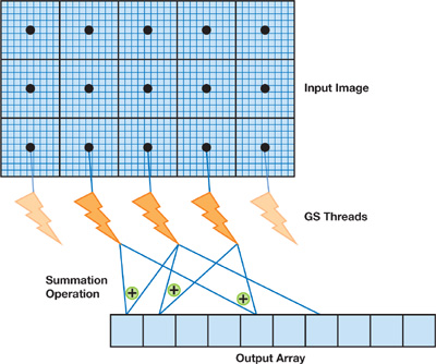
Figure 41-2 Histogram Computation Using the GS
41.4.2 Compressors
The GS programming technique described for histograms can also be used by DXT-like compression schemes, where the size of the output blobs is known in advance. DXT is a compression algorithm that takes a 4x4-pixel block as input. The two most representative colors are chosen and output as two 16-bit (565) color values In addition, sixteen 2-bit indices are output to be used for lookup in a table that contains the two chosen colors and two interpolated colors. The input is 128 bytes and the output is 16 bytes, so the algorithm provides a 6:1 lossy compression (if alpha is discarded).
A GS program can fetch 16 pixels and then write 16 bytes to the frame buffer. This program can use multiple GPU threads at the same time because blocks of input data are independent. In fact, a pixel shader is able to implement a regular DXT compressor because it has a fixed-size output of 8 bytes, and the compressed tile can be written with one pixel with color components of type GL_UNSIGNEDINT32. But a PS cannot be used for compression algorithms—such as for some DCT compression blocks that require writing more than 128 bits of output.
Variable-Length Output
So far we have presented GS algorithms for fixed-size output. However, the pixel shader on modern GPUs is also effective for handling variable-length types of algorithms, especially image processing on a 2D array of pixels. In contrast, computer vision algorithms typically produce variable-length output.
Although some vision applications have been ported to the PS, they are generally more difficult to accelerate because of the differences between 3D graphics and vision in terms of input and output spaces.
- 3D graphics rendering takes a variable-length, compact, and parametric representation as an input (such as vertices, light positions, textures, and geometry) and outputs a fixed-size matrix of pixels.
- Computer vision algorithms take a static matrix of pixels as an input and output a variable-length, compact, and parametric representation of lines or estimates of the camera position, for example. These results are then fed back to some other device (most likely the CPU) for further action.
The inability of the GPU to efficiently carry out processing stages that require variable-length output has hampered its adoption in the field of computer vision. Previous GPU implementations containing many vision algorithms used the PS for regular, data-parallel processing, and then the image buffers were copied back to system memory through the bus for further processing on the CPU (refer to Fung 2005 for more examples of computer vision algorithms on the GPU). These extra steps have the negative side effects of saturating the bus, increasing the system memory footprint, increasing the CPU load, and stalling the GPU.
In the following sections, we describe how the GS unit can be used for algorithms with variable-length output, making the GPU a more viable compute target for computer vision.
41.4.3 The Hough Transform
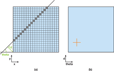
The Hough transform, a classical computer vision algorithm for detecting straight lines in an image, is often
used to help robots identify basic geometry for navigation or industrial quality control. In short, the
algorithm builds a map of all lines—represented with the pair (, d) (
[0, 2p[ and d
0)—that can exist in an image. One pair (x, y) in image space matches a continuous sinusoidal
curve in Hough space, representing all the lines that go through this point. One pair (q, d)
in Hough space matches a line in the image space.
Fung et al. 2005 proposed a GPU implementation of a line detection algorithm based on the Hough transform. However, in their framework, the CPU is still involved in some processing stages, such as searching for maxima in a Hough map. GS programming allows for mapping all stages of a line's detection program to run on the GPU.
A basic line detection algorithm using the Hough transform can be programmed as follows:
- The video GPU hardware unit decodes a frame and writes it in the frame buffer.
- A pixel shader pass applies convolution kernels with thresholds to identify the pixels that have a large gradient.
- A pixel shader pass computes a Hough map (see details later in this section).
- A geometry shader pass looks for n local maxima in the Hough map, identifying n parametric lines in the initial image and writing the dynamic output, made of line coordinates.
The benefit of this GS-based approach is that only a few bytes of data representing the n lines are copied back to the CPU—a good savings in bandwidth and significant CPU offloading.
Figure 41-3b shows a Hough map computed from Figure 41-3a.
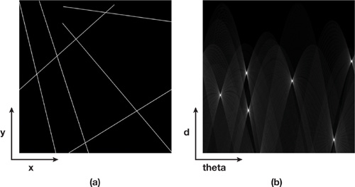
Figure 41-3 Generating a Hough Map
The next step is to run an algorithm to search for maximum values in this map without reading back the image on the CPU. That is easily done using a small GS program (triggered by sending one vertex) that will look for local maxima and emit, for each maximum, four scalars containing the line parameters. In this example, the full algorithm will output six points to be read back by the CPU. To get more parameters, the GS program can fetch the pixels from the input image that belong to this line and count the ones that are lit, thus computing the start position and length of each segment.
The implementation developed by Fung et al. 2005 goes from image space to Hough space, using the VS to plot the sinusoidal curve made of m vertices per pixel of interest. The source image needs to be in system memory and scanned by the CPU (m is the number of samples of ) to send a large number of vertices to the GPU.
There is, however, a simple way to build this map completely on the GPU side with a PS program that is triggered by drawing just a single quad covering the whole rendering target. This approach goes from Hough space to image space. Figure 41-4 shows a point in the Hough map that corresponds to a line in the image space.
The pixel shader code (included on this book's accompanying DVD) finds all the image pixels that belong to a line represented by a point in the Hough map. So for each sample of the Hough map, a PS program is run by rendering a single quad. This program intersects the line with the image rectangle and rasterizes the line, fetching the texels and summing them up to write a single float number (the vote) into the render target (the Hough map). When this process using the PS unit is complete, we use a simple GS program that scans the entire Hough map and outputs a 2D location (two scalars per point) for each local maximum. When the search is over, the number of output points is written to the output buffer, where the CPU program can retrieve it. The first two components of the pixels contain the position of the local maxima in the Hough map. Listing 41-3 provides the GS program that dynamically outputs the location of local maxima.
Example 41-3. GS Program That Dynamically Outputs the Location of Local Maxima
POINT void outputMaxPositionsGS(AttribArray<float4> position : POSITION,
                                AttribArray<float4> color : COLOR,
                                uniform samplerRECT texIn,
                                uniform float BlockSize)
{
  int index=1;
  float sx=color[0].x, sy=color[0].y; // Read block size from
   // vertex color.
   float4 outputPos : POSITION = position[0];  outputPos.y=0;
  for (int j=0; j<sy; j++)
    for (int i=0; i<sx;  i++)
      if(texRECT(texIn, float2(i, j)).r==1.0)
      {
        outputPos.x = -1 + index/128;
        emitVertex(outputPos, float4(i, j, 0, 0) : COLOR);
        index++;
      }
  // Outputting the number of points found
  outputPos.x = -1 ;
  emitVertex(outputPos, float4(index-1, 0, 0, 0) : COLOR);
}
In Listing 41-3 the input data to the GS program has been preprocessed to increase efficiency. We first ran a pixel shader, as shown in Listing 41-4, that, for each pixel, finds the local maximum of all the pixels in the neighborhood and outputs a value of 1 if the current pixel is the maximum, 0 otherwise. The GS code (in Listing 41-3) is very lean for the highest efficiency because, by default, it will run on only one GPU thread.
Example 41-4. PS Program That Searches for Local Maxima (Preparation for GS)
float4 findMaxFirstPassPS(float2 uv : TEX0,
                          uniform samplerRECT texIn) : COLOR
{
  float lum, max;
  float2 t, tcenter;
  float4 valueOut = float4(0, 0, 0, 1);
  for (int j=-KSIZE; j<KSIZE+1; j++) // KSIZE is the size of the window.
  {
    t[1]=uv[1]+j;
    for (int i=-KSIZE; i<KSIZE+1; i++)
    {
      t[0]=uv[0]+i;
      lum=texRECT(texIn, t).r;
      if (lum>max)
      {
        max=lum;
        tcenter=t;
      }
    }
  }
  if (tcenter.x==uv.x && tcenter.y==uv.y)
    valueOut = float4(1, 0, 0, 0);
  return valueOut;
}
41.4.4 Corner Detection
Another classical computer vision technique is corner detection for tracking points of interest. This algorithm can also be implemented efficiently using the GS unit. In general, an input image is processed by a set of convolution kernels, which are very well executed in parallel by PS units. Many filters are used for feature extraction (Canny 1986, Trajkovic and Hedley 1998, Tomasi and Kanade 1991, and Harris and Stephens 1988), and the GPU pixel shaders are very efficient at handling these computationally intensive tasks. The final result of the algorithm is a generally dynamic set of 2D positions.
Implementations of these algorithms (for example, Sinha et al. 2006) usually include a readback of temporary buffers of floating-point data that contain image gradients, eigenvalues, and so forth on the CPU to generate the list of 2D points representing the corners. The number of corners is not known in advance, but it is computed by analyzing local neighborhoods of coefficients. The GS is particularly well suited to accelerating this step because it offers dynamic and compact feedback to the CPU.
Figure 41-5 shows an example of corner detection. To increase parallel processing, we can divide the input space into several subrectangles, each processed by a GS thread that writes its dynamic output in different lines (that is, different y coordinates of the emitted vertices) in the frame buffer.
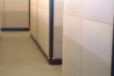
Figure 41-5 The Output of a Corner Detection Algorithm
41.5 Benefits: GPU Locality and SLI
The main advantage of moving data analysis to the GPU is data locality (reducing CPU/GPU exchanges) and CPU offloading. Additionally, if the results of a given algorithm (such as computer vision on live video) are only a few vectors, the performance can scale linearly with the number of GPUs, because CPU processing is not increased significantly by adding GPUs. Figure 41-6 shows a sample configuration with four GeForce 8800 GTX GPUs connected using the SLI interconnect.
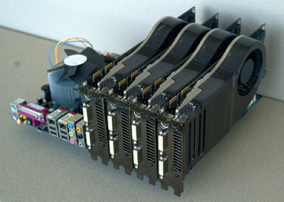
Figure 41-6 NVIDIA SLI System Loaded with Four GeForce 8800 GTX GPUs
Consider the case where the input data is the result of hard drive video decoding. Multiple GPUs decode the incoming video stream in parallel into their respective frame buffers. Once every g frames, each GPU will use the pixel engine to run some image filtering algorithm. Then each will use a GS program to look for some features in the filtered data. This method is optimal because each GPU will send back only a few bytes to system memory, which the CPU will process quickly because it is fully available. If instead we process some stages on the CPU, we will benefit a lot less from SLI scalability because the CPU and bus can saturate and become a bottleneck. Multiple GPU decoding helps even more in some SLI appliances such as the NVIDIA Quadro Plex because the GPUs share the same PCIe path to system memory.
In this case of a video application, using the GS unit to run quick and simple programs works particularly well with the video engine because the programs can run in parallel and the data they work on is shared in the frame buffer with no extra copies.
41.6 Performance and Limits
41.6.1 Guidelines
It's nice having a single execution thread to program algorithms that need to compute statistics before generating variable-length output. On the other hand, using a single execution thread reduces the efficiency of the GPU. Whenever possible, GS algorithms should partition the input space and use multiple threads to exploit the massive parallelism of the GPU. In addition, all per-pixel computations should be done as a pre-process using pixel shaders and stored in a temporary buffer. This way, even a single GS thread working on some data preprocessed by the PS is likely to perform better than if we transferred the image data through the bus back to system memory and processed the image on the CPU.
According to the DirectX 10 specification, the maximum number of scalars that can be written by a GS is 1,024 (4,096 bytes). Based on this limit, the input space has to be divided and processed by different GS threads so that each thread does not emit more than 1,024 scalars. So, if the algorithm permits, it is also beneficial to increase the number of GS threads in order to decrease per-thread output requirements.
Finally, depending on the GPU, GS programs can be optimized by grouping texture fetches and math operations. For example, when we scan an input texture, it is better to traverse the texture in tiles such as 64x64 (this varies with hardware), rather than linearly, to take advantage of the texture cache.
41.6.2 Performance of the Hough Map Maxima Detection
In this section we compare implementing a GPU-CPU algorithm that looks for local maxima in a 1024x1024 Hough map to implementing an algorithm that is completely GPU based. The complete program performs the following steps:
- Load the source image on the GPU.
- Compute the Hough map using a pixel shader.
- Find the local maxima:
- Run a search for local maximum inside 7x7-pixel neighborhoods.
- Scan the intermediate buffer for local maxima output following step 3a.
Table 41-1 shows frame rates and bus utilization for two GPU configurations (one and four GPUs) and two implementations of the algorithm (CPU and GPU). The CPU implementation runs step 3b on the CPU, including a readback in system memory of the output of step 3a. As the numbers show, the complete GPU implementation (steps 3a and 3b), with its minimal feedback, is significantly faster and scales well with the number of GPUs.
Table 41-1. Comparison Between the CPU and GPU Implementations of the Hough Map Local Maxima Detection for One GPU and Four GPUs
| The hardware for these experiments is a GeForce 8800 GTX and an Intel Core 2 2.4 GHz. | ||||
|
Frame Rate |
Bus Bandwidth |
Frame Rate (4 GPUs) |
Bus Bandwidth (4 GPUs) |
|
|
CPU |
58 fps |
232 MB/s |
58 fps |
232 MB/s |
|
GPU |
170 fps |
<1MB/s |
600 fps |
<1MB/s |
41.7 Conclusion
We have demonstrated the basics of the geometry shading unit and shown how it can be used to provide large or variable-length output within GPU threads, or both. Our techniques allow executing some algorithms on the GPU that were traditionally implemented on the CPU, to provide compact and dynamic feedback to an application.
The capabilities of the GS unit allow some multistage computer vision algorithms to remain completely on the GPU, maximizing bus efficiency, CPU offloading, and SLI scaling.
41.8 References
Canny, J. F. 1986. "A Computational Approach to Edge Detection." IEEE Transactions on Pattern Analysis and Machine Intelligence 8(6), pp. 679–698.
Fung, James. 2005. "Computer Vision on the GPU." In GPU Gems 2, edited by Matt Pharr, pp. 649–665. Addison-Wesley.
Fung, James, Steve Mann, and Chris Aimone. 2005. "OpenVIDIA: Parallel GPU Computer Vision." In Proceedings of the ACM Multimedia 2005, pp. 849–852.
Harris, Chris, and Mike Stephens. 1988. "A Combined Corner and Edge Detector." In Proceedings of Fourth Alvey Vision Conference, pp. 147–151.
Microsoft Corporation. 2007. DirectX Web site. http://www.microsoft.com/directx/.
Sinha, Sudipta N., Jan-Michael Frahm, Marc Pollefeys, and Yakup Genc. 2006. "GPU-Based Video Feature Tracking and Matching." Technical Report 06-012, Department of Computer Science, UNC Chapel Hill.
Tomasi, C., and T. Kanade. 1991. "Detection and Tracking of Point Features." Technical Report CMU-CS-91-132, Carnegie Mellon University.
Trajkovic, M., and M. Hedley. 1998. "Fast Corner Detection." Image and Vision Computing 16, pp. 75–87.
- Contributors
- Foreword
- Part I: Geometry
-
- Chapter 1. Generating Complex Procedural Terrains Using the GPU
- Chapter 2. Animated Crowd Rendering
- Chapter 3. DirectX 10 Blend Shapes: Breaking the Limits
- Chapter 4. Next-Generation SpeedTree Rendering
- Chapter 5. Generic Adaptive Mesh Refinement
- Chapter 6. GPU-Generated Procedural Wind Animations for Trees
- Chapter 7. Point-Based Visualization of Metaballs on a GPU
- Part II: Light and Shadows
-
- Chapter 8. Summed-Area Variance Shadow Maps
- Chapter 9. Interactive Cinematic Relighting with Global Illumination
- Chapter 10. Parallel-Split Shadow Maps on Programmable GPUs
- Chapter 11. Efficient and Robust Shadow Volumes Using Hierarchical Occlusion Culling and Geometry Shaders
- Chapter 12. High-Quality Ambient Occlusion
- Chapter 13. Volumetric Light Scattering as a Post-Process
- Part III: Rendering
-
- Chapter 14. Advanced Techniques for Realistic Real-Time Skin Rendering
- Chapter 15. Playable Universal Capture
- Chapter 16. Vegetation Procedural Animation and Shading in Crysis
- Chapter 17. Robust Multiple Specular Reflections and Refractions
- Chapter 18. Relaxed Cone Stepping for Relief Mapping
- Chapter 19. Deferred Shading in Tabula Rasa
- Chapter 20. GPU-Based Importance Sampling
- Part IV: Image Effects
-
- Chapter 21. True Impostors
- Chapter 22. Baking Normal Maps on the GPU
- Chapter 23. High-Speed, Off-Screen Particles
- Chapter 24. The Importance of Being Linear
- Chapter 25. Rendering Vector Art on the GPU
- Chapter 26. Object Detection by Color: Using the GPU for Real-Time Video Image Processing
- Chapter 27. Motion Blur as a Post-Processing Effect
- Chapter 28. Practical Post-Process Depth of Field
- Part V: Physics Simulation
-
- Chapter 29. Real-Time Rigid Body Simulation on GPUs
- Chapter 30. Real-Time Simulation and Rendering of 3D Fluids
- Chapter 31. Fast N-Body Simulation with CUDA
- Chapter 32. Broad-Phase Collision Detection with CUDA
- Chapter 33. LCP Algorithms for Collision Detection Using CUDA
- Chapter 34. Signed Distance Fields Using Single-Pass GPU Scan Conversion of Tetrahedra
- Chapter 35. Fast Virus Signature Matching on the GPU
- Part VI: GPU Computing
-
- Chapter 36. AES Encryption and Decryption on the GPU
- Chapter 37. Efficient Random Number Generation and Application Using CUDA
- Chapter 38. Imaging Earth's Subsurface Using CUDA
- Chapter 39. Parallel Prefix Sum (Scan) with CUDA
- Chapter 40. Incremental Computation of the Gaussian
- Chapter 41. Using the Geometry Shader for Compact and Variable-Length GPU Feedback
- Preface
