
To achieve high efficiency with ray tracing, you must build a pipeline that scales well at every stage. This starts from mesh instance selection and their data processing towards optimized tracing and shading of every hit that you encounter.
Instance data generation
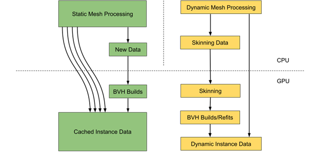
In a common scene, there can be far more static than dynamic objects. However, every dynamic object may take a lot more time for its processing as it requires both vertex data and the corresponding BVH structure to be updated.
It may be a good idea to perform static and dynamic object data processing in parallel on the CPU. This commonly involves instance data extraction and required builds and updates of acceleration structures.
Static mesh data can be efficiently cached on the GPU, including per instance transformation matrix to avoid additional data processing and memory transfers. Each instance alone requires 64 bytes of memory. Using directly mapped video memory (BAR1) is also a good strategy to perform data upload to the GPU.
Dynamic objects selection
Some ray-traced effects, like reflections or shadows, require support for out-of-frustum objects for rendering accuracy. In many cases, this requires including all the objects around the camera within a certain radius.
Even for those objects that reside in a view frustum, it may be not feasible to perform the required updates on each frame. This forces you to come up with some form of prioritization for dynamic objects to select a subset of those to be processed every frame.
For example, you may try to define priority based on a solid angle defined by a bounding sphere and distance to the camera for each object that requires updating. To guarantee that all objects are processed over time, you should also account for the number of frames since the last update.
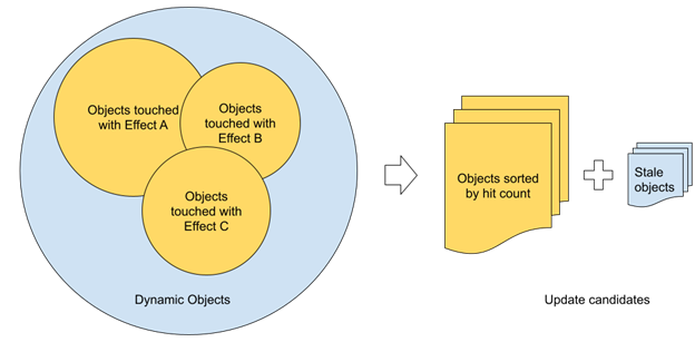
While a solid angle sounds reasonable for priority definition, it may not result in an optimal set of objects selected for updates. For the most part, this comes from the fact that the visibility term is not considered. For ray tracing, visibility can be estimated directly based on the number of rays hitting each object. Object update priority can be directly derived from that.
Such an approach can work a lot better in complex scenarios compared to round-robin updates of dynamic meshes, as it natively distributes the budget of updates to the meshes. This makes the most difference for ray tracing.
With multiple ray-traced effects being used, you can count all the rays from each effect and use a single value per object. Technically, you can use shader atomic increments to account for all the rays on each frame if needed. Practically speaking, using sparse sampling in screen space can reduce the number of potential conflicts if performance feels critical at this point.
Each object gets a unique identifier assigned that can be used as an offset in a buffer to store ray count per object per frame. This buffer uses a set of corresponding CPU-visible buffers for data readback. The readback call can be issued right after the last ray-tracing effect is done and the data should be available for usage during the next frame.
This pipeline introduces at least one frame of latency, which is not a problem due to high data coherency between sequential frames. Special treatment should be taken for newly visible objects that require immediate updates with the highest priority.
Some complex objects may consist of several meshes that may be updated with different frequencies. In certain cases, close-up parts that can be invisible because of occlusion may suddenly cause visual artifacts without the required updates applied. To mitigate that, you can combine visibility driven by ray-object intersections with additional metrics to guarantee lazy updates for the rest of the meshes.
Batched vertex data processing
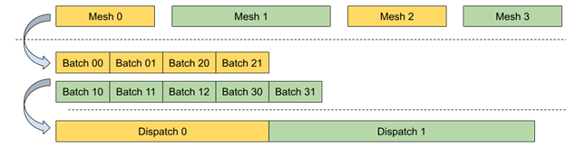
Dynamic mesh vertex data processing requires high parallelism with a minimal number of state changes between individual calls for better performance both on the CPU and GPU sides. This can be partially achieved using a bindless resource model where all required resources are available directly from the shader code on GPU without explicit CPU-side bindings.
Another optimization for potential tasks with low GPU occupancy is to break the whole workload into uniform batches that can be efficiently processed in parallel. Each batch holds all the required attributes to process a range of vertices and apply transformations. This way, you can process many dynamic meshes sharing the same shader using a single Dispatch call.
Shader table data and updates
A shader table holds a set of shader records, which consist of a shader identifier and an optional set of attributes. The attributes are associated with each geometry part for resource bindings and shading accessed through a local root signature.
The shader identifier alone requires 32 bytes of storage. In many cases, the number of unique records is far less than geometries in the TLAS and the data can be filled in parallel with high efficiency directly on the GPU.
The CPU only tracks the list of geometries and corresponding material identifiers. All the data for vertex buffer accesses and material properties can be persistently stored in video memory, with incremental updates for newly created or updated meshes on each frame.
Consider compacting all the records to save memory and allocate shader table storage based on the maximum number of geometries rather than the instance count multiplied by the maximum geometries per instance.
If material data is not included in the record and can be accessed through the InstanceID from the instance descriptor, the total number of records can be equal to the number of unique bottom-level acceleration structures that represent only the geometry part.
For generic cases with specific permutations of geometry and material data, consider packing additional per-mesh attributes directly in the shader record to avoid additional memory indirections while executing shaders associated with hit groups.
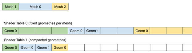
Approaches with fixed geometries per mesh(instance) can simplify memory allocations and data reuse, but the total amount of memory required highly depends on the maximum number of geometries per mesh.
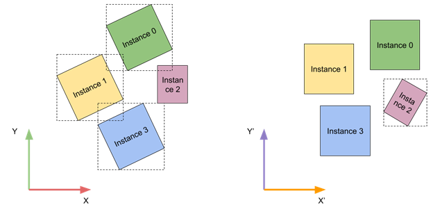
Optimized TLAS rotation
TLAS instances can be more efficient for tracing if their local bounding boxes are axis-aligned. You have no control over individual instance transforms, but you can come up with a global transform for all instances to improve tracing times.
At run time, you can analyze close-up instance transforms and classify them into a number of bins based on their relative rotation. To simplify things further, you account only for rotations around the vertical axis. After classification, you can use a bin that minimizes the relative rotation angle for all instances.
This approach may not be beneficial for every type of content. A good case would be a city environment with a uniform direction of city blocks. One real-world example is the Manhattan borough in New York City, which has its street grid aligned to match the sunset direction.
Vertex data access
It’s usually a good idea to share vertex data across rasterization and the ray-tracing pipeline. In some cases, you can try using an optimized layout just for ray tracing. Positions can be directly evaluated on ray hit and texture coordinates may be the only attribute required during any hit shader execution.
Other attributes can be stored at a lower precision and can be even defined per-primitive, which doesn’t require an additional indirection through the index buffer.
Alpha tested geometry
High-poly geometry, with alpha testing like hair and fur, can be challenging for direct tracing. It may work well in many cases, but sometimes extra treatment should be taken to make sure that performance overhead stays under control.
One way to reduce the tracing cost is to start with pre-tracing, where you trace local neighborhoods for each pixel in screen space, similar to screen space shadows or ambient occlusion techniques. You don’t have to perform this step for every pixel on-screen to make sure that there is no additional overhead. For that, you can use additional data stored in G-buffer surfaces to mark the pixels that belong to hair or fur.
Diffuse global illumination or reflections on rough surfaces may not require precise albedo or alpha testing results. You can store averaged material values per primitive. This way, good results can be achieved by stochastically evaluating opacity during any-hit shader execution without the need for additional per-vertex attributes fetching and interpolation or texture sampling.
If precise alpha testing is still required, it is a good idea to create a simplified, generic any-hit shader and use it where possible. In many cases, it can be enough to use a single set of texture coordinates and texture index to sample from.
Screen space data sampling
Sometimes while shooting rays, you may end up with a primitive intersection landing on screen. This gives you an opportunity to use lighting data from the previous frames after reprojection and improve both the performance and quality of the output. It can work well with diffuse lighting propagation, as ray direction has no effect on the lighting.
Screen space data sampling can be checked before executing any other code in the shader. Any further lighting code can be skipped this way to improve performance.
Alternatively, you can sample just material data from the G-buffer and still run the shading pipeline. Some accuracy should be taken with thin objects, which may require an additional check for their normal after reprojection. Make sure that you are sampling the surface from the right side. Also, this method is worth trying to improve lighting quality when ray-traced effects use simplified materials or shading compared to the main view.
Summary
Use these provided guidelines as a basis for building a performant ray-tracing rendering pipeline with a focus on both GPU and CPU performance. Common API-related best practices are still valid and should also be considered. Additional steps may include adding top-notch features, such as support for micro-meshes and Shader Execution Reordering.
