
Aerial CUDA-Accelerated radio access network (RAN) enables acceleration of telco workloads, delivering new levels of spectral efficiency (SE) on a cloud-native accelerated computing platform, using CPU, GPU, and DPU.
NVIDIA MGX GH200 for Aerial is built on the state-of-the-art NVIDIA Grace Hopper Superchips and NVIDIA Bluefield-3 DPUs. It is designed to accelerate 5G wireless networks end-to-end:
- Virtualized RAN (vRAN) distributed unit (DU)
- Centralized unit (CU)
- User plane function (UPF)
- vRouter
- Network security
This approach to full-stack acceleration delivers leadership performance and spectral efficiency while reducing the total cost of ownership (TCO) and opening new monetization opportunities for a better return on assets (ROA). Aerial CUDA-Accelerated RAN software stack is available in the NVIDIA 6G Research Cloud platform.
Telcos have spent billions to buy the 4G/5G spectrum, and they will be expected to spend again to buy 6G spectrum to meet the ever-increasing mobile user needs.
The ecosystem—including silicon manufacturers, OEMs, and independent software vendors (ISVs)—provides solutions with different performance characteristics. These solutions are mainly based on purpose-built hardware, such as specialized application-specific integrated circuits (ASICs) or system-on-chips (SoCs) for handling the compute-intensive Layer 1 (L1) and Layer 2 (L2) functions.
The challenge has been to balance the level of complexity of algorithms implemented in the RAN solutions compared to the cost and power consumption of that implementation.
Telcos want the ability to disaggregate hardware and software for the RAN workloads, enabling them to build their network on cloud infrastructure, opening up possibilities for software innovations, new differentiating services, control over hardware life cycle management, and improved overall TCO.
vRAN demonstrated the ability of commercial-off-the shelf (COTS) platforms to run the RAN distributed unit (DU) workloads. However, due to computing performance gaps, acceleration was needed, resulting in the fixed function acceleration of certain workloads, such as forward error correction (FEC).
In this post, we discuss the Aerial CUDA-Accelerated RAN advancements for DU-workload acceleration detailing the algorithms used and expected gains, the underlying hardware used, and its ability to both consolidate telco workloads such as DU, centralized unit (CU), and core and use the multi-tenant capabilities for hosting revenue-generating workloads. We conclude with a view on the overall TCO and ROA benefits that a telco can expect to see.
Aerial CUDA-Accelerated RAN
NVIDIA Aerial RAN brings together the Aerial software for 5G and AI frameworks and the NVIDIA accelerated computing platform, enabling TCO reduction and unlocking infrastructure monetization for telcos.
Aerial RAN has the following key features:
- A framework that is software-defined, scalable, modular, highly programmable, and cloud-native, without any fixed function accelerators. It enables the ecosystem to flexibly adopt necessary modules for their commercial products.
- Full-stack acceleration of DU L1, DU L2+, CU, UPF, and other network functions, enabling workload consolidation for maximum performance and spectral efficiency, leading to best-in-class system TCO.
- General purpose infrastructure, with multi-tenancy that can power both traditional workloads and cutting-edge AI applications for best-in-class RoA.
Full-stack acceleration
Full-stack acceleration is enabled with two pillars:
- The NVIDIA Aerial software that enables the acceleration of DU functions L1 and L2.
- Enabling the ecosystem to run and optimize their workloads, such as CU or UPF, on the platform and enabling workload consolidation.
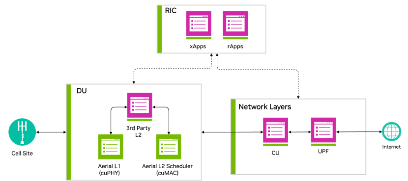
Figure 1 shows that accelerating DU L1 and L2 represents a key aspect of NVIDIA efforts toward full-stack acceleration.
DU acceleration
Aerial has implemented advanced algorithms for improving the spectral efficiency of the RAN protocol stack, covering both DU L1 and L2.
The accelerated L1 and L2 features described in this post are implemented with a common approach that takes advantage of the GPU parallel compute capabilities within the accelerated computing platform.
Figure 2 shows that an MGX GH200 server platform hosts the accelerated L1 cuPHY and L2 MAC Scheduler cuMAC on the same GPU instance, with the CPU hosting the L2+ stack. This demonstrates the power of the GPU-based platform in simultaneously accelerating multiple compute-intensive workloads.

L1 (cuPHY)
Aerial cuPHY is a 3GPP-compliant, GPU-accelerated, full inline implementation of the data and control channels for the RAN physical layer, L1. It provides an L1 high-PHY library that offers unparalleled scalability by using the GPU’s massive computing power and a high degree of parallelism to enable processing of the computationally intensive parts of the L1. It supports standard multi-input multiple output (sMIMO) and massive MIMO (mMIMO) configurations.
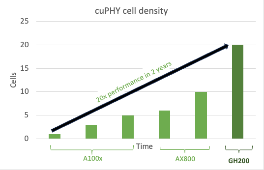
As a software implementation, it enables continuous enhancements and optimizations of the workload, as can be seen by the capacity gains achieved with cuPHY over successive releases, on the AX800 acceleration platform and the new MGX GH200 platform.
Figure 3 shows the cell density gains for sMIMO configuration, 100 MHz 4T4R, with peak throughput performance with software optimizations over time on AX800 and then on the next-generation GH200. This epitomizes the power of a software-defined platform.
Channel estimation, within L1, is a foundational block in any wireless receiver, and an optimized channel estimator can result in significantly improved performance. Traditional approaches to channel estimation include least square (LS) or minimum mean square error (MMSE). A comparison of these approaches is summarized in Table 1.
| Method | Advantages | Disadvantages |
| Least square (LS) | Low complexity | Low performance especially for cell edge and mobile users |
| MMSE (1μs-2μs windows) | Medium complexity and performance | Low performance for cell edge users |
NVIDIA has enhanced cuPHY L1 with a new channel estimator that delivers better performance than the approaches listed in Table 1. This implementation uses the reproducing kernel Hilbert space (RKHS) channel estimator algorithm.
RKHS L1 channel estimation
RKHS channel estimation focuses on the meaningful part of the time domain channel impulse response (CIR), limiting unwanted noise and amplifying the relevant parts of the impulse response (Figure 4).

RKHS requires complex computations, approaching an infinite convex optimization problem. RKHS converts this infinite convex problem into a finite convex problem without any loss of performance.
RKHS is compute-intensive and well-suited for parallel processing on the GPU. Table 2 shows a summary of RKHS gains and compute needs for sMIMO and mMIMO configurations.
| Method | Complexity (FP16) | Spectral efficiency gains | Typical CPU cores (SPR, AVX512) |
| Single Cell – RKHS Channel Estimation with SRS (4T4R, 4DL and 2UL) | 0.5TFlops | ~1.3x for cell edge users with SINR <6dB | ~2 cores |
| Single Cell – RKHS Channel Estimation with SRS (64T64R, 16DL and 8UL) | 5 TFlops | ~2x-3x for all users. | ~20 cores |
The RKHS calculated CIR (Figure 5) closely matches the actual channel, measured in a simulation environment for a tap delay line (TDL) -C channel model, with four antennas and two UL layers.

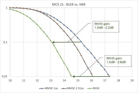
This improved CIR results in significant improvements in the bit error rate (BER) compared to the signal-to-noise-ratio (SNR) curve across a range of modulation and coding schemes (MCS). Figure 6 shows the benefits of RKHS over MMSE (with two different windows, 1μs and 2.3μs), for MCS 15, providing up to 2.5dB gain.
L2 (cuMAC)
The L2 MAC scheduler in the RAN protocol stack plays an important role in deciding how UEs access the radio resources. In turn, this determines the spectral efficiency of the overall network.
For a 5G system, there are many degrees of freedom, including the following:
- Transmission time interval (TTI) slot
- Allocated physical resource blocks (PRBs)
- MCS
- MIMO layer selection
Typical schedulers focus on a single cell, which limits the performance achieved. Table 3 shows a comparison of typical scheduler approaches.
| Scheduler method | Advantages | Disadvantages |
| Single-cell priority-based (round-robin) | Low complexity, all UEs get access to wireless resources based on a priority matrix. | UEs in poor channel conditions can degrade overall cell performance. |
| Single-cell PF | Medium complexity, UEs get allocated resources based on wireless channel conditions. | Cell edge UEs see worse performance compared to the round-robin. |
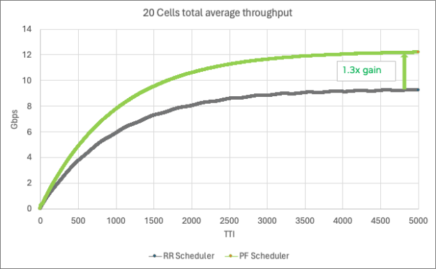
At NVIDIA, we implemented a multi-cell scheduler using the proportional fair (PF) algorithm that delivers better performance than the two approaches listed in Table 3.
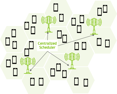
Multi-cell scheduler
The NVIDIA multi-cell scheduler dramatically improves wireless performance by optimizing the scheduling parameters (TTI, PRBs, MCS, and MIMO layers) across a large number of adjacent cells (Figure 7).
Multi-cell scheduling with the PF algorithm requires complex computational logic to solve the various variables across all the cells. This lends itself well to a GPU with massively parallel processing capability. Table 4 summarizes the benefits and compute needs for both sMIMO and mMIMO, with 20 cells jointly scheduled. As you can see, the CPU compute needs are high.
| Method | Complexity (FP16) | Spectral efficiency gains | Typical CPU cores (SPR 2xAVX512) |
| 20-cell scheduling (4TR, 4DL, and 2UL) | 11 TFlops | ~1.3x for all users | ~43 cores |
| 6-cell scheduling (64TR, 16DL, and 8UL) | 33 TFlops | ~1.5x for all users | ~124 cores |
This improved spectral efficiency, measured across all UEs, is shown in Figure 8 for 20 cells of 100MHz 4T4R 4DL/2UL, each cell with 500 active UEs and 16 UE/TTI.
DU combined acceleration gains
In summary, the RKHS channel estimate enables a higher MCS allocation per UE and the multi-cell scheduler represents a significant leap in radio resources scheduling. Both result in significant spectral efficiency gains and are optimally implemented on a GPU.
For example, for a 6-cell 100MHz 64T64R system, achieving SE gains of >2x would need ~240 cores (~8 x 32 core CPUs), requiring additional CPU servers. This is compared to the GPU implementation, where the L1 PHY processing and L2 scheduler are hosted on a single GPU in a single server.
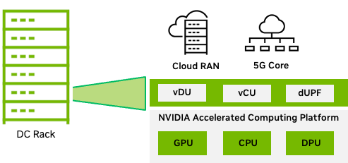
Workload consolidation
As explained earlier in the post, the full-stack acceleration second pillar is about consolidating multiple workloads and accelerating them on the Aerial RAN. This is achieved by taking advantage of the compute resources available across the GPU, CPU, and DPU in the NVIDIA accelerated computing platform.
For telco workloads, the MGX modular and scalable architecture for data centers, a system with the GH200 GPU and Bluefield-3 DPU (Figure 9), provides the necessary compute power to consolidate functions such as RAN CU, RAN intelligent controller (RIC) applications, and core functions such as UPF.
The GH200 Grace Hopper Superchip, combines the NVIDIA Grace and NVIDIA Hopper architectures, using NVIDIA NVLink-C2C to deliver a CPU+GPU coherent memory model for accelerated 5G and AI applications. For more information, see the NVIDIA GH200 Grace Hopper Superchip Architecture whitepaper.
The CU can take advantage of the many Grace CPU cores. The RIC applications, such as xApps that typically include AI/ML techniques to deliver spectral efficiency gains, can be accelerated on the GPU.
As we move further into the network, functions such as UPF benefit from DPU acceleration by using key DPU capabilities:
- GTP encap and decap
- Flow hashing and receive side scaling (RSS)
- Deep packet inspection (DPI)

Workload consolidation (Figure 9), gives the telco the ability to minimize the number of servers deployed in the data center, resulting in an overall improvement in TCO.
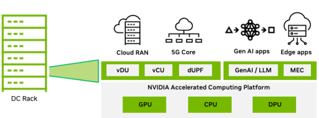
Multi-tenant Aerial RAN
Telcos need a platform that meets the stringent performance and reliability needs of telco workloads, with the ability to host different types of telco workloads (from RAN to core) on a common platform.
Telco RAN infrastructure is significantly underused. With multi-tenant cloud infrastructure, telcos can drive the utilization higher with monetizable applications when there is spare capacity.
The types of workloads that can provide monetization opportunities for telco include generative AI and large language model (LLM)–based, multi-access edge compute (MEC) applications. These have sparked an unprecedented demand in computational demand in the distributed telco edge data centers.
The need to support a multitude of LLM-based applications at the edge is resulting in a substantial proliferation of edge GPU servers dedicated to executing LLM inferencing and various MEC applications.
Figure 10 shows the MGX GH200 platform, which can host all the workloads and help telcos overcome the underutilization of compute resources, reduce their overall energy footprint, and increase the monetization of infrastructure.
Aerial CUDA-Accelerated RAN benefits
So far, we’ve discussed how NVIDIA Aerial software helps improve overall spectral efficiency and how the accelerated computing platform provides processing power to consolidate multiple workloads on the same platform.
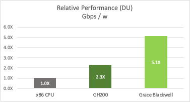
Figure 12 shows an example of telco deployment for 32 cells of massive MIMO cells with 100 MHz bandwidth, including spectral efficiency gains and two generations of platforms (NVIDIA Grace Hopper and NVIDIA Grace Blackwell), compared to a CPU-only implementation.
The multi-tenant platform enables the monetization of AI workloads. A 5-year TCO analysis, where the platform is available ~30% of the time for AI and considering typical GPU pricing per hour, delivers revenue that significantly offsets the platform cost. This ROA has a significant impact on the performance per dollar metric compared to a CPU-only system (Figure 13).
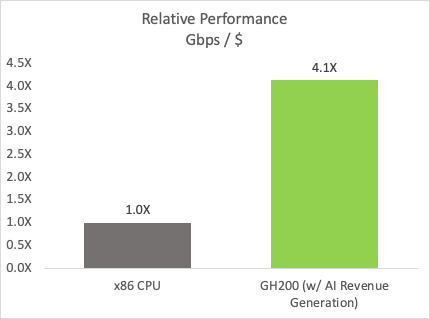
ALT Text: Bar chart shows a 4.1x performance per cost improvement for the GH200 GPU with AI revenue generation over an x86 CPU.
Conclusion
In summary, Aerial RAN delivers optimal TCO and unlocks new revenue opportunities to maximize ROA.
NVIDIA is on a journey to transform the telco infrastructure, built on the NVIDIA accelerated computing platform and enabled with the Aerial software. Aerial CUDA-Accelerated RAN addresses telco aspirations, delivering market-leading wireless capabilities in a TCO-efficient manner with the ability to start monetizing deployed infrastructure in ways not possible with today’s deployed infrastructure.
In this post, we detailed the spectral efficiency gains expected on L1 and L2 with new algorithms and discussed the ability of the GH200 platform to host multiple network workloads, including the ability to accelerate AI workloads for both RAN– and LLM-based workloads. The next-generation NVIDIA platforms will further improve on these key metrics by delivering higher cell density and more workload acceleration.
Aerial CUDA-Accelerated RAN is available as part of the NVIDIA 6G Research Cloud platform. For more information about access, see NVIDIA Aerial.
