As Moore’s law slows down, it becomes increasingly important to develop other techniques that improve the performance of a chip at the same technology process node. Our approach uses AI to design smaller, faster, and more efficient circuits to deliver more performance with each chip generation.
Vast arrays of arithmetic circuits have powered NVIDIA GPUs to achieve unprecedented acceleration for AI, high-performance computing, and computer graphics. Thus, improving the design of these arithmetic circuits would be critical in improving the performance and efficiency of GPUs.
What if AI could learn to design these circuits? In PrefixRL: Optimization of Parallel Prefix Circuits using Deep Reinforcement Learning, we demonstrate that not only can AI learn to design these circuits from scratch, but AI-designed circuits are also smaller and faster than those designed by state-of-the-art electronic design automation (EDA) tools. The latest NVIDIA Hopper GPU architecture has nearly 13,000 instances of AI-designed circuits.
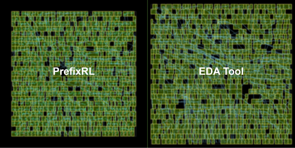
In Figure 1, the circuit corresponds to the (31.4µm², 0.186ns) point in the PrefixRL curve in Figure 5.
The circuit design game
Arithmetic circuits in computer chips are constructed using a network of logic gates (like NAND, NOR, and XOR) and wires. The desirable circuit should have the following characteristics:
- Small: A lower area so that more circuits can fit on a chip.
- Fast: A lower delay to improve the performance of the chip.
- Consume less power: A lower power consumption of the chip.
In our paper, we focus on circuit area and delay. We find that power consumption is well-correlated with area for our circuits of interest. Circuit area and delay are often competing properties, so we want to find the Pareto frontier of designs that effectively trades off these properties. Put simply, we desire the minimum area circuit at every delay.
In PrefixRL, we focus on a popular class of arithmetic circuits called (parallel) prefix circuits. Various important circuits in the GPU such as adders, incrementors, and encoders are prefix circuits that can be defined at a higher level as prefix graphs.
In this work, we specifically ask the question: can an AI agent design good prefix graphs? The state-space of all prefix graphs is large O(2^n^n) and cannot be explored using brute force methods.
A prefix graph is converted into a circuit with wires and logic gates using a circuit generator. These generated circuits are then further optimized by a physical synthesis tool using physical synthesis optimizations such as gate sizing, duplication, and buffer insertion.
The final circuit properties (delay, area, and power) do not directly translate from the original prefix graph properties, such as level and node count, due to these physical synthesis optimizations. This is why the AI agent learns to design prefix graphs but optimizes for the properties of the final circuit generated from the prefix graph.
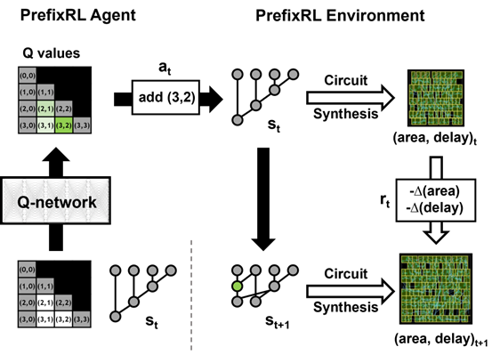
We pose arithmetic circuit design as a reinforcement learning (RL) task, where we train an agent to optimize the area and delay properties of arithmetic circuits. For prefix circuits, we design an environment where the RL agent can add or remove a node from the prefix graph, after which the following steps happen:
- The prefix graph is legalized to always maintain a correct prefix sum computation.
- A circuit is generated from the legalized prefix graph.
- The circuit undergoes physical synthesis optimizations using a physical synthesis tool.
- The area and delay properties of the circuit are measured.
During an episode, the RL agent builds up the prefix graph step-by-step by adding or removing nodes. At each step, the agent receives the improvement in the corresponding circuit area and delay as rewards.
State and action representation and the deep reinforcement learning model
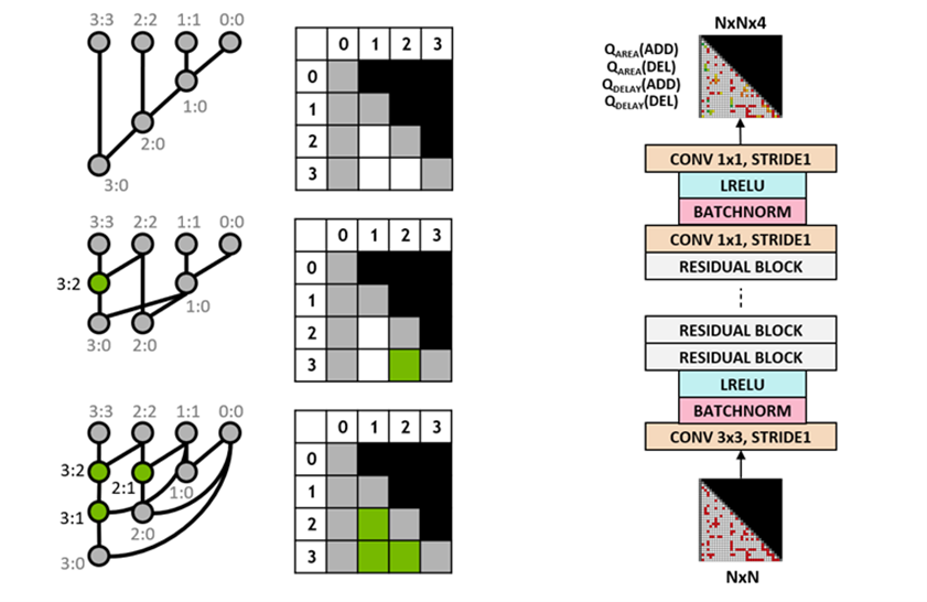
We use the Q-learning algorithm to train the circuit designer agent. We use a grid representation for prefix graphs where each element in the grid uniquely maps to a prefix node. This grid representation is used at both the input and output of the Q-network. Each element in the input grid represents whether a node is present or absent. Each element in the output grid represents the Q-values for adding or removing a node.
We use a fully convolutional neural network architecture for the agent as the input and output of the Q-learning agent are grid representations. The agent separately predicts the Q values for the area and delay properties because the rewards for area and delay are separately observable during training.
Distributed training with Raptor
PrefixRL is a computationally demanding task: physical simulation required 256 CPUs for each GPU and training the 64b case took over 32,000 GPU hours.
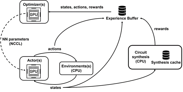
We developed Raptor, an in-house distributed reinforcement learning platform that takes special advantage of NVIDIA hardware for this kind of industrial reinforcement learning (Figure 4).
Raptor has several features that enhance scalability and training speed such as job scheduling, custom networking, and GPU-aware data structures. In the context of PrefixRL, Raptor makes the distribution of work across a mix of CPUs, GPUs, and Spot instances possible.
Networking in this reinforcement learning application is diverse and benefits from the following.
- Raptor’s ability to switch between NCCL for point-to-point transfer to transfer model parameters directly from the learner GPU to an inference GPU.
- Redis for asynchronous and smaller messages such as rewards or statistics.
- A JIT-compiled RPC to handle high volume and low latency requests such as uploading experience data.
Finally, Raptor provides GPU-aware data structures such as a replay buffer that has a multithreaded server to receive experience from multiple workers, and batches data in parallel and prefetches it onto the GPU.
Figure 4 shows that our framework powers concurrent training and data collection, and takes advantage of NCCL to efficiently send actors the latest parameters.
Reward computation
We use a tradeoff weight w from [0,1] to combine the area and delay objectives. We train various agents with various weights to obtain a Pareto frontier of designs that balance the tradeoff between area and delay.
The physical synthesis optimizations in the RL environment can generate various solutions to tradeoff between area and delay. We should drive the physical synthesis tool with the same tradeoff weight for which a particular agent is trained.
Performing physical synthesis optimizations in the loop for reward computation has several advantages.
- The RL agent learns to directly optimize the final circuit properties for a target technology node and library.
- The RL agent can optimize the properties of the target arithmetic circuit and its surrounding logic jointly by including the surrounding logic during physical synthesis.
However, performing physical synthesis is a slow process (~35 seconds for 64b adders), which can greatly slow RL training and exploration.
We decouple reward calculation from state update as the agent only needs the current prefix graph state to take actions, and not circuit synthesis nor previous rewards. Thanks to Raptor, we can offload the lengthy reward calculation onto a pool of CPU workers to perform physical synthesis in parallel, while actor agents step through the environment without needing to wait.
When rewards are returned by the CPU workers, the transitions can then be inserted into the replay buffer. Synthesis rewards are cached to avoid redundant computation whenever a state is reencountered.
Results
The RL agents learn to design circuits tabula rasa purely through learning with feedback from synthesized circuit properties. Figure 5 shows the latest results* that use 64b adder circuits designed by PrefixRL, Pareto-dominated adder circuits from a state-of-the-art EDA tool in area and delay.
The best PrefixRL adder achieved a 25% lower area than the EDA tool adder at the same delay. These prefix graphs that map to Pareto optimal adder circuits after physical synthesis optimizations have irregular structures.
Conclusion
To the best of our knowledge, this is the first method using a deep reinforcement learning agent to design arithmetic circuits. We hope that this method can be a blueprint for applying AI to real-world circuit design problems: constructing action spaces, state representations, RL agent models, optimizing for multiple competing objectives, and overcoming slow reward computation processes such as physical synthesis.
For more information and comparisons against other approaches, see PrefixRL: Optimization of Parallel Prefix Circuits using Deep Reinforcement Learning (preprint).
