
Oracle is one of the top cloud service providers in the world, supporting over 22,000 customers and reporting revenue of nearly $4 billion per quarter and annual growth of greater than 40%. Oracle Cloud Infrastructure (OCI) is growing at an even faster rate and offers a complete cloud infrastructure for every workload.
Having added 11 regions in the last 18 months, OCI currently offers 41 regions and supports hosted, on-premises, hybrid, and multi-cloud deployments. It enables customers to run a mix of custom-built, third-party ISVs and Oracle applications on a scalable architecture. OCI provides scalable networking and tools to support security, observability, compliance, and cost management.
One of the differentiators of OCI is its ability to offer high-performance computing (HPC), Oracle Exadata and Autonomous Database, and GPU-powered applications such as AI and machine learning (ML), with fast infrastructure-as-a-service (IaaS) performance that rivals dedicated on-premises infrastructure. A key component to delivering this high performance is a scalable, low-latency network that supports remote direct memory access (RDMA). For more details, see First Principles: Building a High-Performance Network in the Public Cloud.
Networking challenge of HPC and GPU-powered compute
A commonality across HPC applications, GPU-powered AI workloads, and the Oracle Autonomous Database on Exadata is that they all run as distributed workloads. Data processing occurs simultaneously on multiple nodes, using a few dozen to thousands of CPUs and GPUs. These nodes must communicate with each other, share intermediate results in multi-stage problem solving with gigabytes to petabytes of storage to access common data, and often assemble the results of distributed computing into a cohesive solution.
These applications require high throughput and low latency to communicate across nodes to solve problems quickly. Amdahl’s law states that the speedup from parallelizing a task is limited by how much of the task is inherently serial and cannot be parallelized. The amount of time needed to transfer information between nodes adds inherently serial time to the task because nodes must wait for the data transfer to complete and for the slowest node in the task to finish before starting the next parallelizable part of the job.
For this reason, the performance of the cluster network becomes paramount, and an optimized network can enable a distributed compute cluster to deliver results much sooner than the same computing resources running on a slower network. This time-saving speeds job completion and reduces costs.
What is RDMA?
RDMA is remote direct memory access, the most efficient means of transferring data between different machines. It enables a server or storage appliance to communicate and share data over a network without making extra copies and without interrupting the host CPU. It is used for AI, big data, and other distributed technical computing workloads.
Traditional networking interrupts the CPU multiple times and makes multiple copies of the data being transmitted as it passes from the application through the OS kernel, to the adapter, then back up the stack on the receiving end. RDMA uses only one copy of the data on each end and typically bypasses the kernel, placing data directly in the receiving machine’s memory without interrupting the CPU.
This process enables lower latency and higher throughput on the network and lower CPU utilization for the servers and storage systems. Today, the majority of HPC, technical computing, and AI applications can be accelerated by RDMA. For more details, see How RDMA Became the Fuel for Fast Networks.
What is InfiniBand?
InfiniBand is a lossless network optimized for HPC, AI, big data, and other distributed technical computing workloads. It typically supports the highest bandwidth available (currently 400 Gbps per connection) for data center networks and RDMA, enabling machines to communicate and share data without interrupting the host CPU.
InfiniBand adapters offload networking and data movement tasks from the CPU and feature an optimized, efficient networking stack, enabling CPUs, GPUs, and storage to move data rapidly and efficiently. The InfiniBand adapters and switches can also perform specific compute and data aggregation tasks in the network, mostly oriented around message passing interface (MPI) collective operations.
This in-network computing speeds up distributed applications, enabling faster problem solving. It also frees up server CPU cores and improves energy efficiency. InfiniBand can also automatically balance traffic loads and reroute connections around broken links.
As a result, many computing clusters that are dedicated to AI, HPC, big data, or other scientific computing run on an InfiniBand network to provide the highest possible performance and efficiency. When distributed computing performance is the top priority, and the adoption of a specialized stack of network adapters, switches, and management is acceptable, InfiniBand is the network of choice. But a data center might choose to run Ethernet instead of InfiniBand, for other reasons.
What is RoCE?
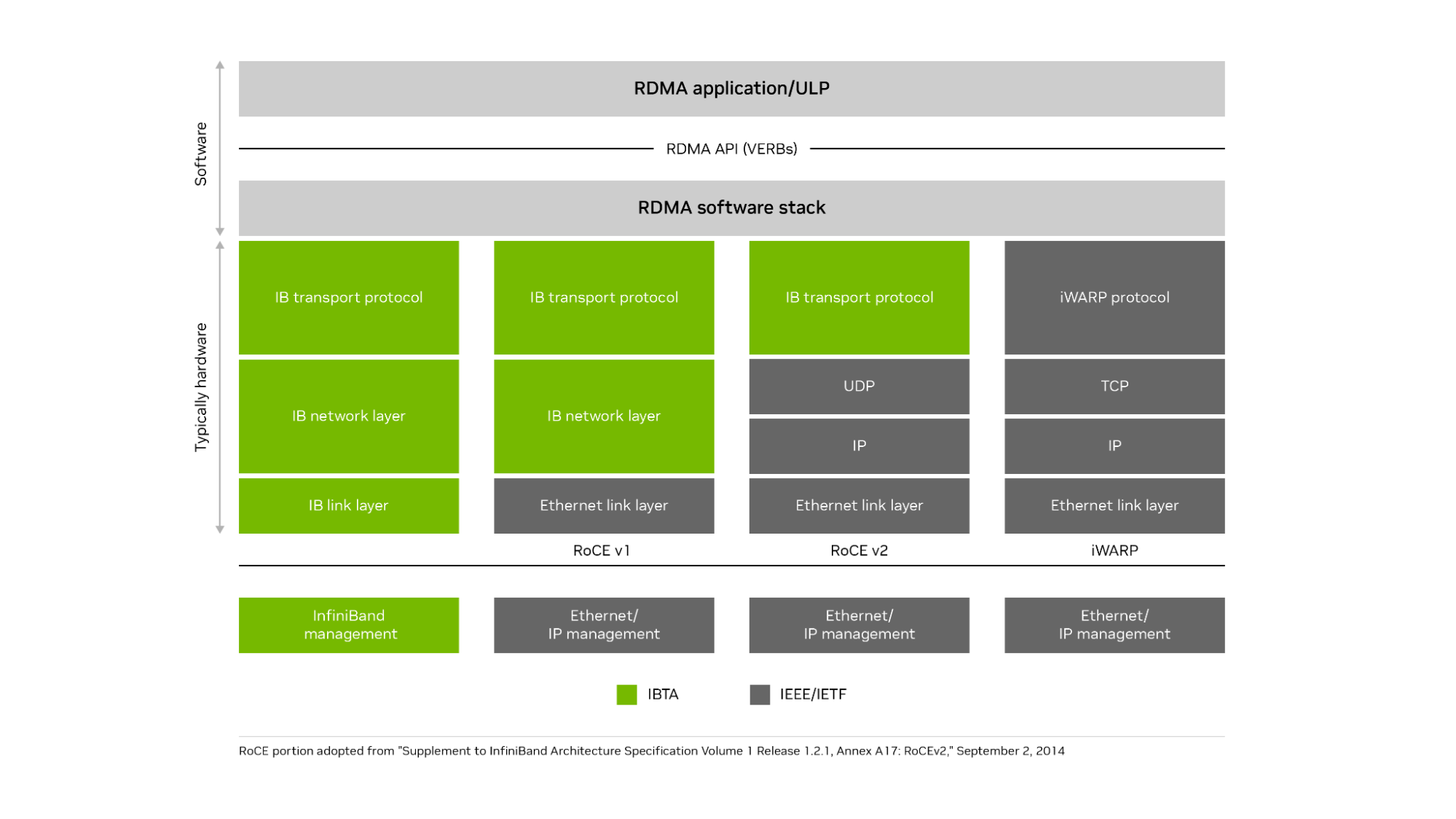
RDMA over Converged Ethernet (RoCE) is an open standard enabling remote direct memory access and network offloads over an Ethernet network. The current and most popular implementation is RoCEv2. It uses an InfiniBand communication layer running on top of UDP (Layer 4) and IP (Layer 3), which runs on top of high-speed Ethernet (Layer 2) connections.
It also supports remote direct memory access, zero-copy data transfers, and bypassing the CPU when moving data. Using the IP protocol on Ethernet enables RoCEv2 to be routable over standard Ethernet networks. RoCE brings many of the advantages of InfiniBand to Ethernet networks. RoCEv2 runs the InfiniBand transport layer over UDP and IP protocols on an Ethernet network. iWARP ran the iWARP protocol on top of the TCP protocol on an Ethernet network but failed to gain popular adoption because of performance and implementation challenges (Figure 1).
How do RoCE networks address scalability?
RoCE operates most efficiently on networks with very low levels of packet loss. Traditionally, small RoCE networks use priority flow control (PFC), based on the IEEE 802.1Qbb specification, to make the network lossless. If any destination is too busy to process all incoming traffic, it sends a pause frame to the next upstream switch port, and that switch holds traffic for the time specified in the pause frame.
If needed, the switch can also send a pause frame up to the next switch in the fabric and eventually onto the originator of the traffic flow. This flow control avoids having the port buffers overflow on any host or switch and prevents packet loss. You can manage up to eight traffic classes with PFC, each class having its own flows and pauses separate from the others.
However, PFC has some limitations. It operates only at the Layer 2 (Ethernet) level of the Open System Interconnection (OSI) 7-layer model, so it cannot work across different subnets. While a subnet can have thousands or millions of nodes, a typical subnet is limited to 254 IP addresses and consists of a few racks (often one rack) within a data center, which does not scale for large distributed applications.
PFC operates on a coarse-grained port level and cannot distinguish between flows sharing that port. Also, if you use PFC in a multi-level switch fabric, congestion at one destination switch for one flow can spread to multiple switches and block unrelated traffic flows that share one port with the congested flow. The solution is usually to implement a form of congestion control.
Congestion management for large RoCE networks
The TCP protocol includes support for congestion management based on dropped packets. When an endpoint or switch is overwhelmed by a traffic flow, it drops some packets. When the sender fails to receive an acknowledgment from the transmitted data, the sender assumes the packet was lost because of network congestion, slows its rate of transmission, and retransmits the presumably lost data.
This congestion management scheme does not work well for RDMA on Ethernet (and therefore for RoCE). RoCE does not use TCP and the process of waiting for packets to timeout and then retransmitting the lost data introduces too much latency—and too much variability in latency or jitter—for efficient RoCE operation.
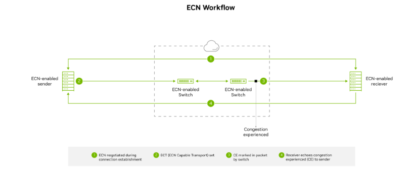
Large RoCE networks often implement a more proactive congestion control mechanism known as explicit congestion notification (ECN), in which the switches mark packets if congestion occurs in the network. The marked packets alert the receiver that congestion is imminent, and the receiver alerts the sender with a congestion notification packet or CNP. After receiving the CNP, the sender knows to back off, slowing down the transmission rate temporarily until the flow path is ready to handle a higher rate of traffic.
Congestion control works across Layer 3 of the OSI model, so it functions across different subnets and scales up to thousands of nodes. However, it requires setting changes to both switches and adapters supporting RoCE traffic. Implementation details of when switches mark packets for congestion, how quickly senders back off sending data, and how aggressively senders resume high-speed transmissions are all critical to determining the scalability and performance of the RoCE network.
Other Ethernet-based congestion control algorithms include quantized congestion notification (QCN) and data center TCP (DCTCP). In QCN, switches notify flow senders directly with the level of potential congestion, but the mechanism functions only over L2. Consequently, it cannot work across more than one subnet. DCTCP uses the sender’s network interface card (NIC) to measure the round-trip time (RTT) of special packets to estimate how much congestion exists and how much the sender must slow down data transmissions.
But DCTCP lacks a fast start option to quickly start or resume sending data when no congestion exists, places a heavy load on host CPUs, and does not have a good mechanism for the receiver to communicate with the sender. In any case, DCTCP requires TCP, so it does not work with RoCE.
Smaller RoCE networks using newer RDMA-capable ConnectX SmartNICs from NVIDIA, or newer NVIDIA BlueField DPUs, can use Zero Touch RoCE (ZTR). ZTR enables excellent RoCE performance without setting up PFC or ECN on the switch, which greatly simplifies network setup. However, initial deployments of ZTR have been limited to small RoCE network clusters, and a more scalable version of ZTR that uses RTT for congestion notification is still in the proving stages.
How OCI implements a scalable RoCE network
OCI determined that certain cloud workloads required RDMA for maximum performance. These include AI, HPC, Exadata, autonomous databases, and other GPU-powered applications. Out of the two standardized RDMA options on Ethernet, they chose RoCE for its performance and wider adoption.
The RoCE implementation needed to scale to run across clusters containing thousands of nodes and deliver consistently low latency to ensure an excellent experience for cloud customers.
After substantial research, testing, and careful design, OCI decided to customize their own congestion control solution based on the data center quantized congestion notification (DC-QCN) algorithm, which they optimized for different RoCE-accelerated application workloads. The OCI DC-QCN solution is based on ECN with minimal use of PFC.
A separate network for RoCE
OCI built a separate network for RoCE traffic because the needs of the RDMA network tend to differ from the regular data center network. The different types of application traffic, congestion control, and routing protocols each prefer to have their own queues. Each NIC typically supports only eight traffic classes, and the NIC and switch configuration settings and firmware might be different for RDMA from non-RDMA workloads. For these reasons, having a separate Ethernet network for RoCE traffic and RoCE-accelerated applications makes sense.
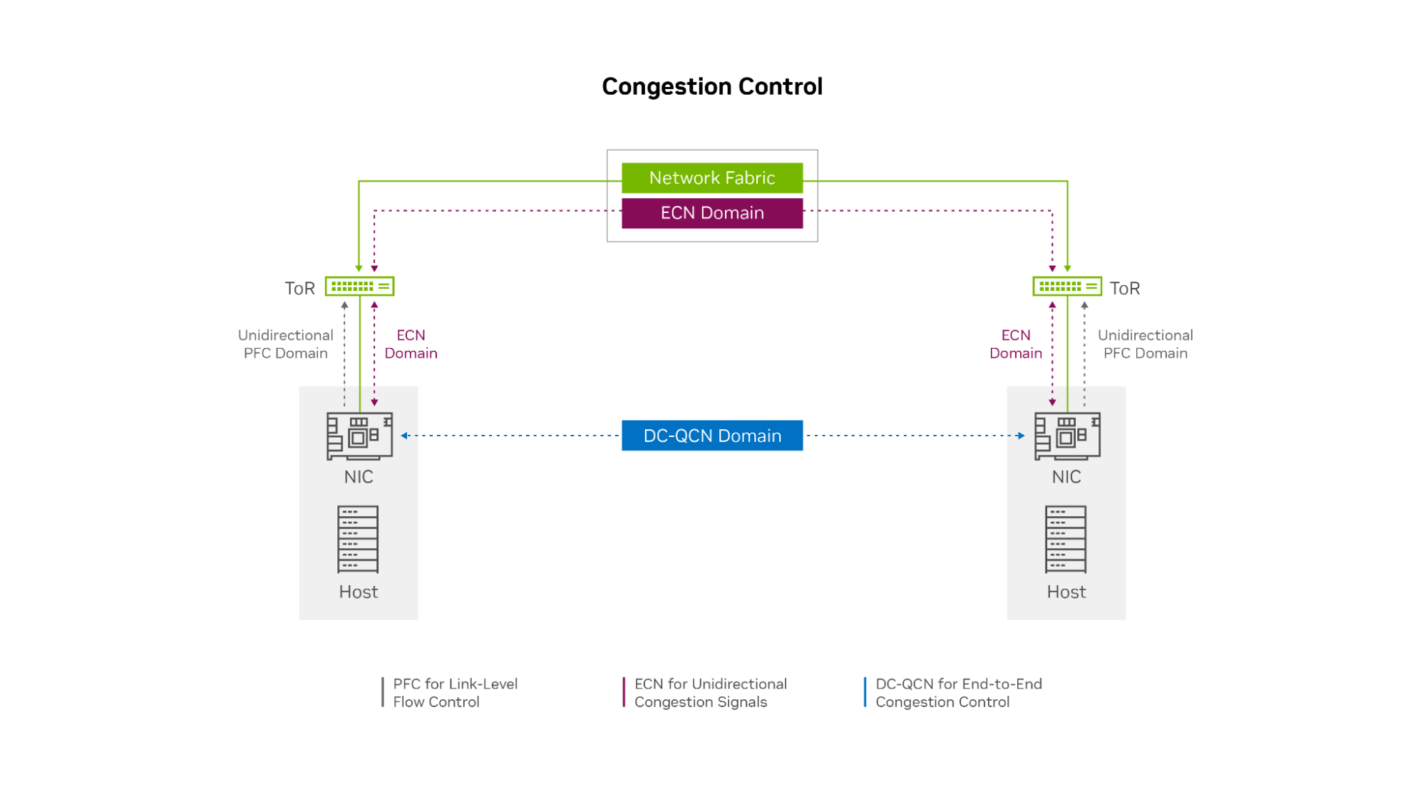
Limited use of PFC at the edge
OCI implemented a limited level of PFC, only unidirectionally at the network edge. Endpoints can ask the top-of-rack (ToR) switch to pause transmission if their NICs buffer fills up. However, the ToR switches never ask the endpoints to pause and do not pass pause requests up the network to leaf or spine switches. This process prevents head-of-line blocking and congestion spreading if the incoming traffic flow rate temporarily exceeds the receiver’s ability to process and buffer data.
The ECN mechanism ensures that PFC is very rarely needed. In the rare case that a receiving node’s NIC buffer is temporarily overrun while the ECN feedback mechanism is activating, PFC enables the receiving node to briefly pause the incoming data flow until the sender receives the CNPs and slows its transmission rate.
In this sense, you can use PFC as a last resort safeguard to prevent buffer overrun and packet loss at the network edge (at the endpoints). OCI envisions that with the next generation of ConnectX SmartNICs, you might not need PFC, even at the edge of the network.
Multiple classes of congestion control
OCI determined that they need at least three customized congestion control profiles within DC-QCN for different workloads. Even within the world of distributed applications that require RDMA networking, the needs vary across the following categories:
- Latency sensitive, requiring consistently low latency throughput
- Sensitive, high throughput
- Mixed, requires a balance of low-latency and high throughput
The primary setting for customizing congestion control is the probability P (ranging from 0 to 1) of the switch adding the ECN marking to an outgoing packet, based on queue thresholds Kmin and Kmax. P starts at 0 when the switch queue is not busy, which means it has no chance of congestion.
When the port queue reaches Kmin, the value P rises above 0, increasing the chance that any packet is marked with ECN. When the queue fills to value Kmax, P is set to Pmax (typically 1), meaning every outgoing packet of that flow on that switch is marked with ECN. Different DC-QCN profiles typically have a no-congestion range where P is 0, a potential congestion range where P is between 0 and 1, and a congestion range where P is 1.
A more aggressive set of thresholds has lower values for Pmin and Pmax, resulting in earlier ECN packet marking and lower latency but possibly also lower maximum throughput. A relaxed set of thresholds has higher values for Pmin and Pmax, marking fewer packets with ECN, resulting in some higher latencies but also higher throughput.
To the right side of Figure 4 are three examples of OCI workloads: HPC, Oracle Autonomous DataBase and Exadata Cloud Service, and GPU workloads. These services use different RoCE congestion control profiles. HPC workloads are latency-sensitive and give up some throughput to guarantee lower latency. Consequently, Kmin and Kmax are identical and low (aggressive), and at a low amount of queuing, they mark 100% of all packets with ECN.
Most GPU workloads are more forgiving on latency but need maximum throughput. The DC-QCN profile gradually marks more packets as buffers ramp from Kmin to Kmax and sets those values relatively higher to enable switch buffers to get closer to full before signaling to flow endpoints that they slow down.
For Autonomous Database and Exadata Cloud Service workloads, the required balance of latency and bandwidth is in between. Marking or increasing P value gradually increases between Kmin and Kmax, but these values are set at lower threshold values than for GPU workloads.
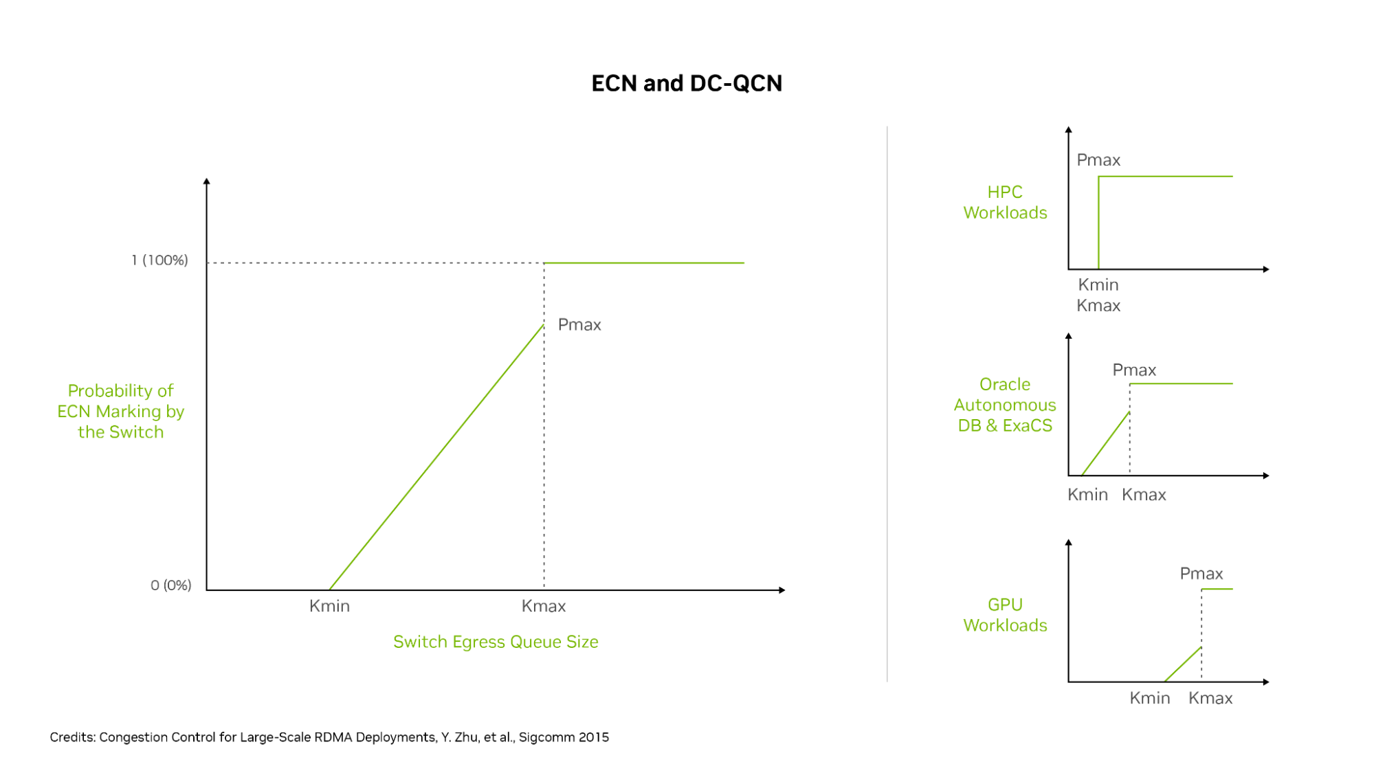
With these settings, HPC flows get 100% ECN packet marking as soon as the queues hit the Kmin level (which is the same here as Kmax) for early and aggressive congestion control engagement. Oracle Autonomous Database and Exadata flows see moderately early ECN marking, but only a portion of packets is marked until buffers reach the Kmax level.
Other GPU workloads have a higher Kmin setting so ECN marking does not begin until switch queues are relatively fuller, and 100% ECN marking only happens when the queues are close to full. Different workloads get the customized congestion control settings needed to provide the ideal balance of latency and throughput for maximum application performance.
Leveraging advanced network hardware
An important factor in achieving high performance for RoCE networks is the type of network card used. The NIC offloads the networking stack, including RDMA, to a specialized chip to offload the work from the CPUs and GPUs. OCI uses ConnectX SmartNICs, which have market-leading network performance for both TCP and RoCE traffic.
These SmartNICs also support rapid PFC and ECN reaction times for detecting ECN-marked packets or PFC pause frames, sending CNPs, and adjusting the data transmission rates downward and upward in response to congestion notifications.
NVIDIA has been a long time leader in the development and support of RDMA, PFC, ECN, and DC-QCN technology, and a leader in high-performance GPUs and GPU connectivity. The advanced RoCE offloads in ConnectX enable higher throughput and lower latency on the OCI network, and their rapid, hardware-based ECN reaction times help ensure that DC-QCN functions smoothly.
By implementing an optimized congestion control scheme on a dedicated RoCE network, plus a combination of localized PFC, multiple congestion control profiles, and NVIDIA network adapters, OCI has built a very scalable cluster network. It’s ideal for distributed workloads, such as AI and ML, HPC, and Oracle Autonomous Database, and delivers high throughput and low-latency performance close to what an InfiniBand network can achieve.
Emphasizing data locality
With optimizing cluster network performance, OCI also manages data locality to minimize latency. With the large size of RoCE-connected clusters that often span multiple data center racks and halls, even in an era of 100-, 200-, and 400-Gbps networking connections, the speed of light has not changed, and longer cables result in higher latency.
Connections to different halls in the data center traverse more switches, and each switch hop adds some nanoseconds to connection latency. OCI shares server locality information with both its customers and the job scheduler, so they can schedule jobs to use servers and GPUs that are close to each other in the network.
For example, the NVIDIA Collective Communication Library (NCCL) understands the OCI network topology and server locality information and can schedule GPU work accordingly. So, the compute and storage connections traverse fewer switch hops and shorter cable lengths, to reduce the average latency within the cluster.
It also sends less traffic to spine switches, simplifying traffic routing and load-balancing decisions. OCI also worked with its switch vendors to make the switches more load-aware, so flows can be routed to less-busy connections. Each switch generally has two connections up and down the network, enabling multiple datapaths for any flow.
Conclusion
By investing in a dedicated RoCE network with an optimized implementation of DC-QCN, advanced ConnectX NICs, and customized congestion control profiles, OCI delivers a highly scalable cluster that supports accelerated computing for many different workloads and applications. OCI cluster networks simultaneously deliver high throughput and low latency. For small clusters, latency-half the round trip time-can be as little as 2 microseconds. For large clusters, latency is typically under 4 microseconds. For extremely large superclusters, latencies are in the range of 4-8 microseconds, with most traffic seeing latencies at the lower end of this range.
Oracle Cluster Infrastructure uses an innovative approach to deliver scalable, RDMA-powered networking on Ethernet for a multitude of distributed workloads, providing higher performance and value to their customers.
For more information, see the following resources:
