使用 GPU 对网络数据包进行内联处理是一种数据包分析技术,可用于许多不同的应用领域:信号处理、网络安全、信息收集、输入重建等。
这些应用程序类型的主要要求是尽快将接收到的数据包移动到 GPU 内存中,以触发负责对其执行并行处理的 CUDA 内核。
总体思路是创建一个连续的异步管道,能够将数据包从网卡直接接收到 GPU 内存中。您还可以使用 CUDA 内核来处理传入的数据包,而无需同步 GPU 和 CPU 。
有效的应用程序工作流包括使用无锁通信机制在以下播放器组件之间创建一个协调的连续异步管道:
- network controller 向 GPU 内存提供接收到的网络数据包
- CPU 用于查询网络控制器以获取有关接收到的数据包的信息
- GPU 用于接收数据包信息并直接将其处理到 GPU 内存中
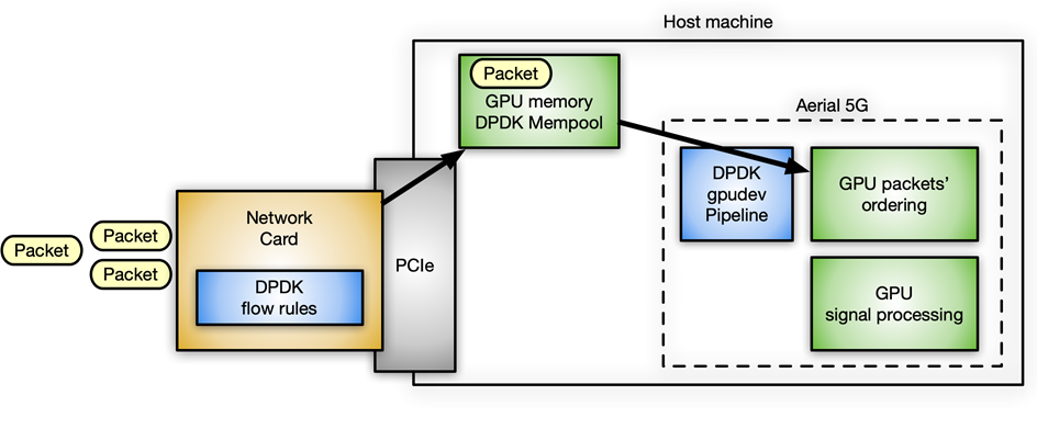
图 1 显示了使用 NVIDIA GPU 和 ConnectX 网卡的加速内联数据包处理应用程序的典型数据包工作流场景。
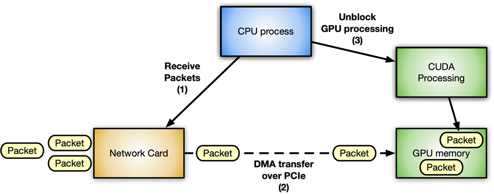
在这种情况下,避免延迟是至关重要的。不同组件之间的通信越优化,系统的响应速度就越快,吞吐量也就越高。每一步都必须在所需资源可用时以内联方式进行,而不会阻塞任何其他等待的组件。
您可以清楚地识别两种不同的流:
- Data flow :通过 PCIe 总线在网卡和 GPU 之间交换优化的数据(网络数据包)。
- Control flow : CPU 协调 GPU 和网卡。
数据流
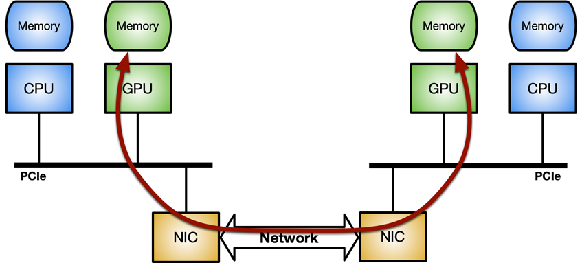
关键是优化网络控制器和 GPU 之间的数据移动(发送或接收数据包)。它可以通过 GPUDirect RDMA 技术实现,该技术使用 PCI Express 总线接口的标准功能,在 NVIDIA GPU 和第三方对等设备(如网卡)之间实现直接数据路径。
GPUDirect RDMA 依赖于 NVIDIA GPU 在 PCI Express 基址寄存器( BAR )区域上公开部分设备内存的能力。有关更多信息,请参阅 CUDA 工具包文档中的 使用 GPUDirect-RDMA 开发 Linux 内核模块 。 在现代服务器平台上对 GPUDirect-RDMA 进行基准测试 文章对使用不同系统拓扑的标准 IB 谓词执行网络操作(发送和接收)时的 GPUDirect RDMA 带宽和延迟进行了更深入的分析。
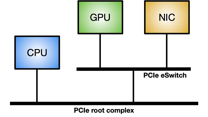
要在 Linux 系统上启用 GPUDirect RDMA ,需要 nvidia-peermem 模块(在 CUDA 11.4 及更高版本中提供)。图 3 显示了最大化 GPUDirect RDMA 内部吞吐量的理想系统拓扑:在 GPU 和 NIC 之间使用专用 PCIe 交换机,而不是通过与其他组件共享的系统 PCIe 连接。
控制流
CPU 是网络控制器和 GPU 之间协调和同步活动的主要参与者,用于唤醒 NIC ,将数据包接收到 GPU 内存中,并通知 CUDA 工作负载有新数据包可供处理。
在处理 GPU 时,强调 CPU 和 GPU 之间的异步非常重要。例如,假设一个简单的应用程序在主循环中执行以下三个步骤:
- 接收数据包。
- 处理数据包。
- 发回修改过的数据包。
在本文中,我将介绍在这种应用程序中实现控制流的四种不同方法,包括优缺点。
方法 1
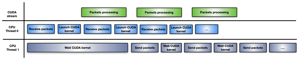
图 4 显示了最简单但最不有效的方法:单个 CPU 线程负责接收数据包,启动 CUDA 内核来处理它们,等待 CUDA 内核完成,并将修改后的数据包发送回网络控制器。
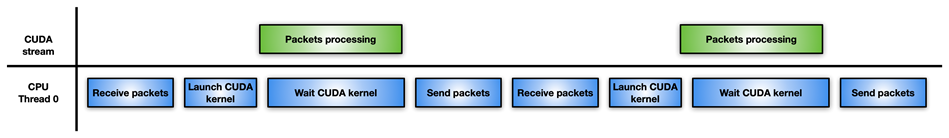
如果数据包处理不是那么密集,那么这种方法的性能可能会比只使用 CPU 处理数据包而不使用 GPU 更差。例如,您可能具有高度的并行性来解决数据包上的一个困难且耗时的算法。
方法 2
在这种方法中,应用程序将 CPU 工作负载分成两个 CPU 线程:一个用于接收数据包并启动 GPU 处理,另一个用于等待 GPU 处理完成并通过网络传输修改后的数据包(图 5 )。
这种方法的一个缺点是,每次累积数据包的突发都会启动一个新的 CUDA 内核。 CPU 必须为每次迭代支付 CUDA 内核启动延迟。如果 GPU 被淹没,数据包处理可能不会立即执行,从而导致延迟。
方法 3
图 6 显示了第三种方法,它涉及使用 CUDA 持久内核。
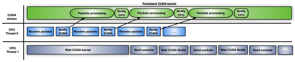
CUDA 持久内核是一个预启动的内核,它正忙着等待来自 CPU 的通知:新数据包已经到达并准备好进行处理。当数据包准备好后,内核通知第二个 CPU 线程它可以向前发送数据包。
实现此通知系统的最简单方法是使用忙等待标志更新机制在 CPU 和 GPU 之间共享一些内存。虽然 GPUDirect RDMA 旨在从第三方设备直接访问 GPU 内存,但您可以使用这些 API 创建 GPU 内存的完全有效的 CPU 映射。 CPU 驱动的拷贝的优点是所涉及的开销小。现在可以通过 GDRCopy 库启用此功能。
直接映射 GPU 内存进行信令,可以从 CPU 修改内存,并在轮询期间降低 GPU 的延迟成本。您也可以将该标志放在从 GPU 可见的 CPU 固定内存中,但 CUDA 内核轮询 CPU 内存标志将消耗更多 PCIe 带宽并增加总体延迟。
这种快速解决方案的问题在于它有风险,而且 CUDA 编程模型不支持它。 GPU 内核不能被抢占。如果写得不正确,持久内核可能会永远循环。此外,长期运行的持久内核可能会失去与其他 CUDA 内核、 CPU 活动、内存分配状态等的同步。
它还拥有 GPU 资源(例如,流式多处理器),如果 GPU 真的忙于其他任务,这可能不是最好的选择。如果您使用 CUDA 持久内核,那么您的应用程序必须具有良好的处理能力。
方法 4
最后一种方法是前两种方法的混合解决方案:使用 CUDA 流内存操作 要等待或更新通知标志,请在 CUDA 流上预启动一个 CUDA 内核,每接收一组数据包。
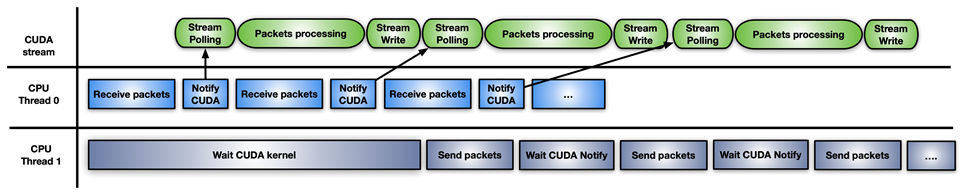
这种方法的不同之处在于 GPU HW (使用cuStreamWaitValue)轮询内存标志,而不是阻塞 GPU 流式多处理器,并且只有在数据包准备就绪时才会触发数据包的处理内核。
类似地,当处理内核结束时,cuStreamWriteValue通知负责发送数据包的 CPU 线程数据包已被处理。
这种方法的缺点是,应用程序必须不时地用cuStreamWriteValue+cuStreamWaitValue内核+ CUDA 的新序列重新填充 GPU ,以避免在空流没有准备好处理更多数据包的情况下浪费执行时间。这里的 CUDA 图是在流上重新发布的好方法。
不同的方法适用于不同的应用程序模式。
DPDK 和 GPUdev
数据平面开发工具包 ( DPDK )是一组库,用于帮助加速在各种 CPU 体系结构和不同设备上运行的数据包处理工作负载。
在 DPDK 21.11 中, NVIDIA 引入了一个名为 GPUdev 的新库,以在 DPDK 的上下文中引入 GPU 的概念,并增强 CPU 、网卡和 GPU 之间的对话。 GPUdev 在 DPDK 22.03 中扩展了更多功能。
图书馆的目标如下:
- 介绍从 DPDK 通用库管理的 GPU 设备的概念。
- 实现基本的 GPU 内存交互,隐藏特定于 GPU 的实现细节。
- 减少网卡、 GPU 设备和 CPU 之间的间隙,增强通信。
- 将 DPDK 集成简化为 GPU 应用程序。
- 通过通用层公开 GPU 特定于驱动程序的功能。
对于特定于 NVIDIA 的 GPU , GPUdev 库功能通过 CUDA 驱动程序 DPDK 库 。要为 NVIDIA GPU 启用所有gpudev可用功能, DPDK 必须构建在具有 CUDA 库和 GDRCopy 的系统上。
有了这个新库提供的功能,您可以轻松地通过 GPU 实现内联数据包处理,同时处理数据流和控制流。
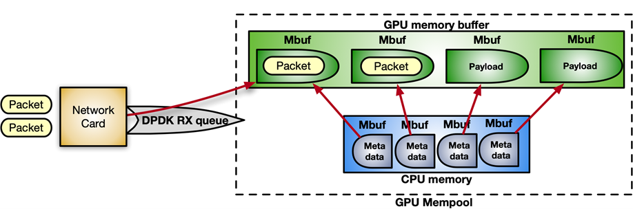
DPDK 在 mempool 中接收数据包,这是一个连续的内存块。通过以下指令序列,您可以启用 GPUDirect RDMA 在 GPU 内存中分配 mempool ,并将其注册到设备网络中。
struct rte_pktmbuf_extmem gpu_mem; gpu_mem.buf_ptr = rte_gpu_mem_alloc(gpu_id, gpu_mem.buf_len, alignment)); /* Make the GPU memory visible to DPDK */ rte_extmem_register(gpu_mem.buf_ptr, gpu_mem.buf_len, NULL, gpu_mem.buf_iova, NV_GPU_PAGE_SIZE); /* Create DMA mappings on the NIC */ rte_dev_dma_map(rte_eth_devices[PORT_ID].device, gpu_mem.buf_ptr, gpu_mem.buf_iova, gpu_mem.buf_len)); /* Create the actual mempool */ struct rte_mempool *mpool = rte_pktmbuf_pool_create_extbuf(... , &gpu_mem, ...);图 8 显示了 mempool 的结构:
对于控制流,要启用 CPU 和 GPU 之间的通知机制,可以使用gpudev通信列表:在 CPU 内存和 CUDA 内核之间的共享内存结构。列表中的每一项都可以保存接收到的数据包的地址(mbufs),以及一个用于更新处理该项状态的标志(数据包就绪、处理完成等)。
struct rte_gpu_comm_list { /** DPDK GPU ID that will use the communication list. */ uint16_t dev_id; /** List of mbufs populated by the CPU with a set of mbufs. */ struct rte_mbuf **mbufs; /** List of packets populated by the CPU with a set of mbufs info. */ struct rte_gpu_comm_pkt *pkt_list; /** Number of packets in the list. */ uint32_t num_pkts; /** Status of the packets’ list. CPU pointer. */ enum rte_gpu_comm_list_status *status_h; /** Status of the packets’ list. GPU pointer. */ enum rte_gpu_comm_list_status *status_d;
};
伪代码示例:
struct rte_mbuf * rx_mbufs[MAX_MBUFS]; int item_index = 0; struct rte_gpu_comm_list *comm_list = rte_gpu_comm_create_list(gpu_id, NUM_ITEMS); while(exit_condition) { ... // Receive and accumulate enough packets nb_rx += rte_eth_rx_burst(port_id, queue_id, &(rx_mbufs[0]), rx_pkts); // Populate next item in the communication list. rte_gpu_comm_populate_list_pkts(&(p_v->comm_list[index]), rx_mbufs, nb_rx); ... index++; }为简单起见,假设应用程序遵循 CUDA 持久内核场景, CUDA 内核上的轮询端看起来类似于以下代码示例:
__global__ void cuda_persistent_kernel(struct rte_gpu_comm_list *comm_list, int comm_list_entries) { int item_index = 0; uint32_t wait_status; /* GPU kernel keeps checking exit condition as it can’t be preempted. */ while (!exit_condition()) { wait_status = RTE_GPU_VOLATILE(comm_list[item_index].status_d[0]); if (wait_status != RTE_GPU_COMM_LIST_READY) continue; if (threadIdx.x < comm_list[item_index]->num_pkts) { /* Each CUDA thread processes a different packet. */ packet_processing(comm_list[item_index]->addr, comm_list[item_index]->size, ..); } __syncthreads(); /* Notify packets in the items have been processed */ if (threadIdx.x == 0) { RTE_GPU_VOLATILE(comm_list[item_index].status_d[0]) = RTE_GPU_COMM_LIST_DONE; __threadfence_system(); } /* Wait for new packets on the next communication list entry. */ item_index = (item_index+1) % comm_list_entries; } }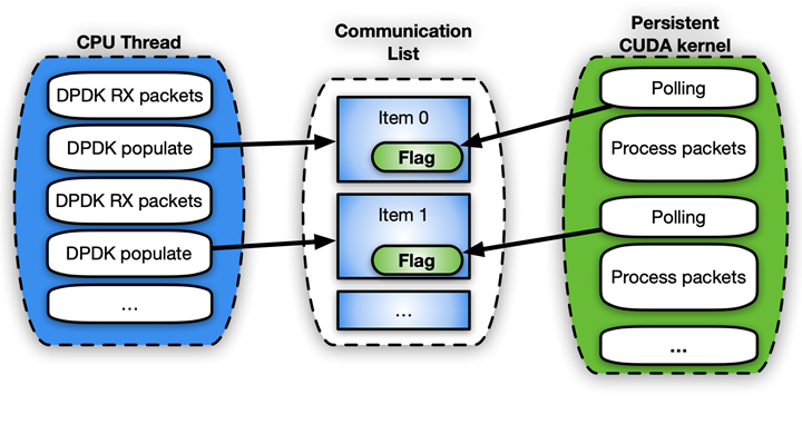
NVIDIA 使用 DPDK gpudev库进行内联数据包处理的一个具体用例位于 空中应用框架 中,用于构建高性能、软件定义的 5G 应用程序。在这种情况下,必须在 GPU 内存中接收数据包,并根据 5G 特定的数据包头重新排序,这样可以在重新排序的有效负载上开始信号处理。
l2fwd nv 应用程序
为了提供如何实现内联数据包处理和使用 DPDK gpudev库的实际示例,l2fwd-nv示例代码已在 /NVIDIA/l2fwd-nv GitHub repo 上发布。这是使用 GPU 功能增强的普通 DPDK l2fwd示例的扩展。应用程序布局是接收数据包,交换每个数据包的 MAC 地址(源和目的地),并传输修改后的数据包。
L2fwd-nv为本文讨论的所有方法提供了一个实现示例,以供比较:
- CPU 仅限
- CUDA 每组数据包的内核数
- CUDA 持久内核
- CUDA 图
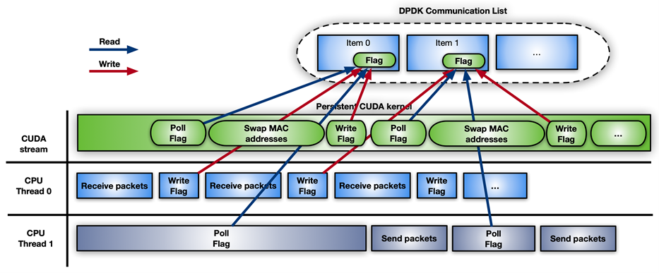
例如,图 11 显示了带有 DPDK gpudev对象的 CUDA 持久内核的时间线。
为了测量l2fwd-nv相对于 DPDK testpmd数据包生成器的性能,图 12 中使用了两个与 CPU 背靠背连接的千兆字节服务器: Intel Xeon Gold 6240R 、 PCIe gen3 专用交换机、 Ubuntu 20.04 、 MOFED 5.4 和 CUDA 11.4 。
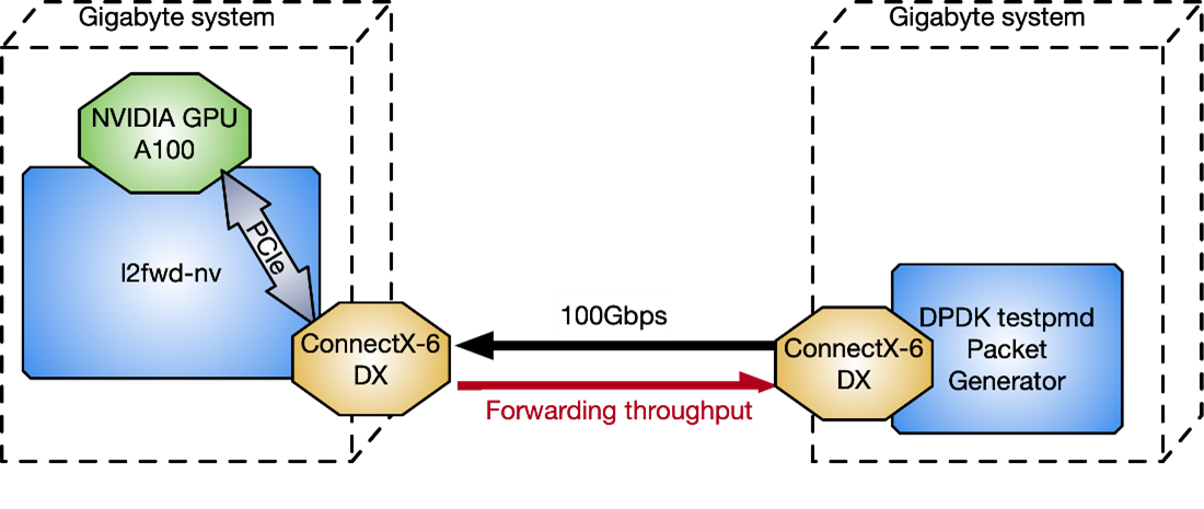
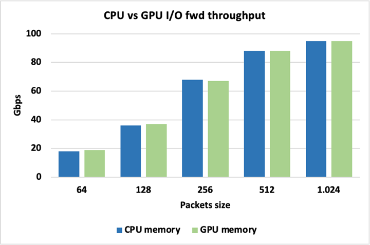
图 13 显示,当为数据包使用 CPU 或 GPU 内存时,峰值 I / O 吞吐量是相同的,因此使用其中一个不会带来固有的损失。这里的数据包被转发而不被修改。
为了突出不同 GPU 数据包处理方法之间的差异,图 14 显示了方法 2 ( CUDA 内核/数据包集)和方法 3 ( CUDA 持久内核)之间的吞吐量比较。这两种方法都将数据包大小保持在 1024 字节,在触发 GPU 工作以交换数据包的 MAC 地址之前,改变累积数据包的数量。
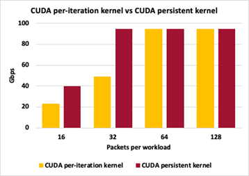
对于这两种方法,每次迭代 16 个数据包会导致控制平面中的交互过多,并且无法达到峰值吞吐量。由于每次迭代 32 个数据包,持久化内核可以跟上峰值吞吐量,而每次迭代的单个启动仍然有太多的控制平面开销。对于每次迭代 64 和 128 个数据包,这两种方法都能够达到峰值 I / O 吞吐量。这里的吞吐量测量不是零丢失数据包。
结论
在本文中,我讨论了使用 GPU 优化内联数据包处理的几种方法。根据应用程序的需要,您可以应用多个工作流模型,以减少延迟,从而提高性能。 DPDK gpudev 库还有助于简化您的编码工作,以在最短的时间内获得最佳结果。
其他需要考虑的因素,取决于应用程序,包括在触发数据包处理之前,在接收端积累足够的数据包需要花费多少时间,有多少线程可用于尽可能多地增强不同任务之间的并行性,以及内核在执行中应该持续多长时间。