
GPU Gems 3
GPU Gems 3 is now available for free online!
The CD content, including demos and content, is available on the web and for download.
You can also subscribe to our Developer News Feed to get notifications of new material on the site.
Chapter 21. True Impostors
Eric Risser
University of Central Florida
In this chapter we present the true impostors method, an efficient technique for adding a large number of simple models to any scene without rendering a large number of polygons. The technique utilizes modern shading hardware to perform ray casting into texture-defined volumes. With this method, multiple depth layers representing non-height-field surface data are associated with quads.
Like traditional impostors, the true impostors approach rotates the quad around its center so that it always faces the camera. Unlike the traditional impostors technique, which displays a static texture, the true impostors technique uses the pixel shader to ray-cast a view ray through the quad in texture-coordinate space to intersect the 3D model and compute the color at the intersection point. The texture-coordinate space is defined by a frame with the center of the quad as the origin.
True impostors supports self-shadowing on models, reflections, and refractions, and it is an efficient method for finding distances through volumes.
21.1 Introduction
Most interesting environments, both natural as well as synthetic ones, tend to be densely populated with many highly detailed objects. Rendering this kind of environment typically requires a huge set of polygons, as well as a sophisticated scene graph and the overhead to run it.
As an alternative, image-based techniques have been explored to offer practical remedies to these limitations. Among current image-based techniques is impostors, a powerful technique that has been used widely for many years in the graphics community. An impostor is a two-dimensional image texture that is mapped onto a rectangular card or billboard, producing the illusion of highly detailed geometry. Impostors can be created on the fly or precomputed and stored in memory. In both cases, the impostor is accurate only for a specific viewing direction. As the view deviates from this ideal condition, the impostor loses accuracy. The same impostor is reused until its visual error surpasses a given arbitrary threshold and it is replaced with a more accurate impostor.
The true impostors method takes advantage of the latest graphics hardware to achieve an accurate geometric representation that is updated every frame for any arbitrary viewing angle. True impostors builds off previous per-pixel displacement mapping techniques. It also extends the goal of adding visually accurate subsurface features to any arbitrary surface by generating whole 3D objects on a billboard. The true impostors method distinguishes itself from previous per-pixel displacement mapping impostor methods because it does not restrict viewing, yet it provides performance optimizations and true multiple refraction.
21.2 Algorithm and Implementation Details
A single four-channel texture can hold four height fields, which can represent many volumes. More texture data can be added to extend this to any shape. We generate a billboard (that is, a quad that always faces the camera) for use as a window to view our height fields from any given direction, as illustrated in Figure 21-1.
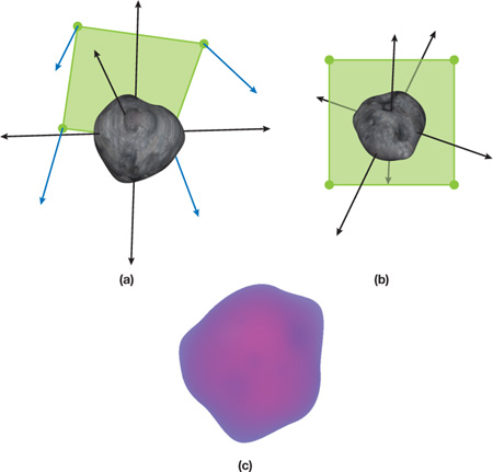
Figure 21-1 Generating a Billboard
The image in Figure 21-1b shows a representation of our billboard's texture coordinates after they have been transformed into a 3D plane and rotated around our functions (model) in the center (represented by the asteroid). Figure 21-1a shows the perspective of our function that would be displayed on our billboard, and Figure 21-1c shows the function (in bitmap form) that represents our asteroid.
To expand on this concept, see Figure 21-2. In Figure 21-2a, we see the component of this method that operates on geometry in world space. The camera is viewing a quad that is rotated so that its normal is the vector produced between the camera and the center of the quad. As shown, texture coordinates are assigned to each vertex. Figure 21-2b reveals texture space, traditionally a two-dimensional space, where we add a third dimension, W, and shift the UV coordinates by –0.5. In Figure 21-2c, we simply set the W component of our texture coordinates to 1.
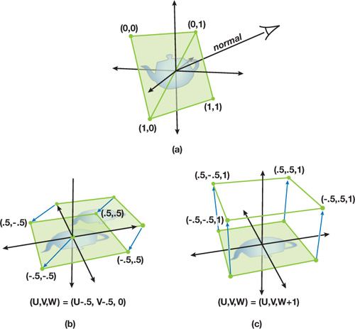
Figure 21-2 The Geometry of True Impostors Projections
Keep in mind that the texture map only has UV components, so it is bound to two dimensions and therefore can only be translated along the UV plane, where any value of W will reference the same point. Although bound to the UV plane, the texture map can represent volume data by treating each of the four variables that makes up a pixel as points on the W axis. In Figure 21-3, we can see the projection of the texture volume into three-dimensional space. The texture coordinates of each vertex are rotated around the origin—the same way our original quad was rotated around its origin—to produce the billboard.
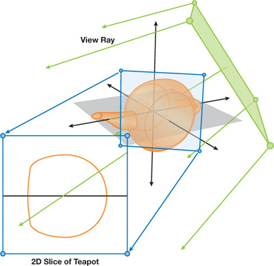
Figure 21-3 Projecting View Rays to Take a 2D Slice
Now we introduce the view ray into our concept. The view ray is produced by casting a ray from the camera to each vertex. During rasterization, both the texture coordinates and the view rays stored in each vertex are interpolated across the fragmented surface of our quad. This is conceptually similar to ray casting or ray tracing because we now have a viewing screen of origin points, where each point has a corresponding vector to define a ray. It should also be noted that each individual ray projects as a straight line onto our texture map plane and therefore takes a 2D slice out of the 3D volume to evaluate for collisions. This is shown in detail in Figure 21-3.
At this point two separate options exist, depending on the desired material type. For opaque objects, ray casting is the fastest and most accurate option available. A streamlined approach to this option is presented in Policarpo and Oliveira 2006, using a ray march followed by a binary search, as shown in Figure 21-4. Figure 21-4a shows a linear search in action. The view ray is tested at regular intervals to see whether it has intersected with a volume. Once the first intersection is found, it and the previous point are used as the beginning and ending points of a binary search space. This space is then repeatedly divided in half until the exact point of intersection into the volume is found.
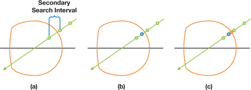
Figure 21-4 Ray March and Binary Search to Determine Volume Intersection
Because of the nature of GPU design, it is impractical from an efficiency standpoint to exit out of a loop early; therefore, the maximum number of ray marches and texture reads must be performed no matter how early in the search the first collision is found. Rather than ignore this "free" data, we propose a method for adding rendering support for translucent material types through using a localized approximation. Instead of performing a binary search along the viewing ray, we use the points along the W axis to define a linear equation for each height field. We then test these linear equations for intersection with the view ray in a similar fashion as shown in Tatarchuk 2006.
As shown in Figure 21-5, the intersection that falls between the upper and lower bounding points is kept as the final intersection point. Because the material is translucent, the normal is checked for this point. Plus, the view ray is refracted according to a refractive index either held constant for the shader or stored in an extra color channel in one of the texture maps. Once the new view direction is discovered, the ray march continues and the process is repeated for any additional surfaces that are penetrated. By summing the distances traveled through any volume, we determine the total distance traveled through our model and use it to compute the translucency for that pixel.
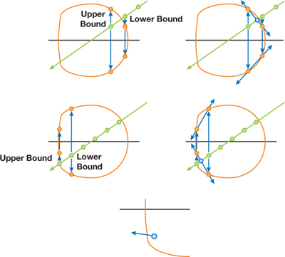
Figure 21-5 Expanding Intersection Tests to Support Translucence
21.3 Results
The true impostors method performs similarly to other per-pixel displacement mapping techniques. However, there are concerns that are unique to this method: for example, performance is fill-rate dependent. Plus, billboards can occlude neighbors, so it is crucial to perform depth sorting on the CPU to avoid overdraw.
On the other hand, because the true impostors method is fill-rate dependent, the level of detail is intrinsic, which is a great asset.
With the true impostors method, you can represent more geometry on screen at once than you could using standard polygonal means. Figure 21-6 shows a model of Jupiter rendered using a quarter-of-a-million asteroids to constitute its ring. This technique was implemented in C++ using DirectX 9. All benchmarks were taken using an NVIDIA GeForce 6800 Go GPU and two GeForce 7800 GPUs run in SLI.
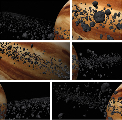
Figure 21-6 A Model of Jupiter Consisting of a Quarter Million Impostors
Although the vertex processor is crucial for this method, the resulting operations do not overload the vertex processing unit or noticeably reduce performance. The performance of this technique is primarily determined by the fragment processing unit speed, the number of pixels on the screen, the number of search steps for each pixel, and the choice of rendering technique. When ray casting was done, the performance mirrored that of Policarpo and Oliveira 2006 because of the similar ray casting technique used in both methods. Table 21-1 reports the performance of this technique as "ray casting."
Table 21-1. Performance Comparison of Both Methods
|
A model of Jupiter consisting of a quarter-of-a-million impostors was used for the ray casting results. A single impostor with true multiple refraction was used for the ray tracing results. |
||||
|
Video Card |
Resolution |
Loops |
Frame Rate |
|
|
Ray casting |
GeForce Go 6800 |
1024x768 |
10/8 |
10–12 |
|
GeForce 7800 SLI |
1024x768 |
10/8 |
35–40 |
|
|
Ray tracing |
GeForce Go 6800 |
800x600 |
20 |
7–8 |
|
GeForce 7800 SLI |
800x600 |
20 |
25–30 |

Figure 21-7 A Translucent True Impostor
No comparisons were made between the performances of the two techniques because of the fundamentally different rendering solutions they both offer. The only generalized performance statement we can make about the two techniques is that they both have been shown to achieve real-time frame rates on modern graphics hardware.
21.4 Conclusion
True impostors is a quick, efficient method for rendering large numbers of animated, opaque, reflective, or refractive objects on the GPU. It generates impostors with little rendering error and offers an inherent per-pixel level of detail. By representing volume data as multiple height fields stored in traditional texture maps, the vector processing nature of modern GPUs is exploited and a high frame rate is achieved, but with a low memory requirement.
By abandoning the restrictions that inherently keep per-pixel displacement mapping a subsurface detail technique, we achieved a new method for rendering staggering amounts of faux geometry. We accomplished this not by blurring the line between rasterization and ray tracing, but by using a hybrid approach that takes advantage of the best each has to offer.
21.5 References
Blinn, James F. 1978. "Simulation of Wrinkled Surfaces." In Proceedings of SIGGRAPH '78, pp. 286–292.
Cook, Robert L. 1984. "Shade Trees." In Computer Graphics (Proceedings of SIGGRAPH 84) 18(3), pp. 223–231.
Hart, John C. 1996. "Sphere Tracing: A Geometric Method for the Antialiased Ray Tracing of Implicit Surfaces." The Visual Computer 12(10), pp. 527–545.
Hirche, Johannes, Alexander Ehlert, Stefan Guthe, and Michael Doggett. 2004. "Hardware-Accelerated Per-Pixel Displacement Mapping." In Proceedings of the 2004 Conference on Graphics Interface, pp. 153–158.
Kaneko, Tomomichi, Toshiyuki Takahei, Masahiko Inami, Naoki Kawakami, Yasuyuki Yanagida, Taro Maeda, and Susumu Tachi. 2001. "Detailed Shape Representation with Parallax Mapping." In Proceedings of the ICAT 2001 (The 11th International Conference on Artificial Reality and Telexistence), pp. 205–208.
Kautz, Jan, and H. P. Seidel. 2001. "Hardware-Accelerated Displacement Mapping for Image Based Rendering." In Proceedings of Graphics Interface 2001, pp. 61–70.
Kolb, Andreas, and Christof Rezk-Salama. 2005. "Efficient Empty Space Skipping for Per-Pixel Displacement Mapping." In Proceedings of the Vision, Modeling and Visualization Conference 2005, pp. 359–368.
Patterson, J. W., S. G. Hoggar, and J. R. Logie. 1991. "Inverse Displacement Mapping." Computer Graphics Forum 10(2), pp. 129–139.
Policarpo, Fabio, Manuel M. Oliveira, and João L. D. Comba. 2005. "Real-Time Relief Mapping on Arbitrary Polygonal Surfaces." In Proceedings of the 2005 Symposium on Interactive 3D Graphics and Games, pp. 155–162.
Policarpo, Fabio, and Manuel M. Oliveira. 2006. "Relief Mapping of Non-Height-Field Surface Details." In Proceedings of the 2006 Symposium on Interactive 3D Graphics and Games, pp. 55–62.
Sloan, Peter-Pike, and Michael F. Cohen. 2000. "Interactive Horizon Mapping." In Proceedings of the Eurographics Workshop on Rendering Techniques 2000, pp. 281–286.
Tatarchuk, N. 2006. "Dynamic Parallax Occlusion Mapping with Approximate Soft Shadows." In Proceedings of ACM SIGGRAPH Symposium on Interactive 3D Graphics and Games 2006, pp. 63–69.
Welsh, Terry. 2004. "Parallax Mapping with Offset Limiting: A Per-Pixel Approximation of Uneven Surfaces." Infiscape Technical Report. Available online at http://www.cs.cmu.edu/afs/cs/academic/class/15462/web.06s/asst/project3/parallax_mapping.pdf.
- Contributors
- Foreword
- Part I: Geometry
-
- Chapter 1. Generating Complex Procedural Terrains Using the GPU
- Chapter 2. Animated Crowd Rendering
- Chapter 3. DirectX 10 Blend Shapes: Breaking the Limits
- Chapter 4. Next-Generation SpeedTree Rendering
- Chapter 5. Generic Adaptive Mesh Refinement
- Chapter 6. GPU-Generated Procedural Wind Animations for Trees
- Chapter 7. Point-Based Visualization of Metaballs on a GPU
- Part II: Light and Shadows
-
- Chapter 8. Summed-Area Variance Shadow Maps
- Chapter 9. Interactive Cinematic Relighting with Global Illumination
- Chapter 10. Parallel-Split Shadow Maps on Programmable GPUs
- Chapter 11. Efficient and Robust Shadow Volumes Using Hierarchical Occlusion Culling and Geometry Shaders
- Chapter 12. High-Quality Ambient Occlusion
- Chapter 13. Volumetric Light Scattering as a Post-Process
- Part III: Rendering
-
- Chapter 14. Advanced Techniques for Realistic Real-Time Skin Rendering
- Chapter 15. Playable Universal Capture
- Chapter 16. Vegetation Procedural Animation and Shading in Crysis
- Chapter 17. Robust Multiple Specular Reflections and Refractions
- Chapter 18. Relaxed Cone Stepping for Relief Mapping
- Chapter 19. Deferred Shading in Tabula Rasa
- Chapter 20. GPU-Based Importance Sampling
- Part IV: Image Effects
-
- Chapter 21. True Impostors
- Chapter 22. Baking Normal Maps on the GPU
- Chapter 23. High-Speed, Off-Screen Particles
- Chapter 24. The Importance of Being Linear
- Chapter 25. Rendering Vector Art on the GPU
- Chapter 26. Object Detection by Color: Using the GPU for Real-Time Video Image Processing
- Chapter 27. Motion Blur as a Post-Processing Effect
- Chapter 28. Practical Post-Process Depth of Field
- Part V: Physics Simulation
-
- Chapter 29. Real-Time Rigid Body Simulation on GPUs
- Chapter 30. Real-Time Simulation and Rendering of 3D Fluids
- Chapter 31. Fast N-Body Simulation with CUDA
- Chapter 32. Broad-Phase Collision Detection with CUDA
- Chapter 33. LCP Algorithms for Collision Detection Using CUDA
- Chapter 34. Signed Distance Fields Using Single-Pass GPU Scan Conversion of Tetrahedra
- Chapter 35. Fast Virus Signature Matching on the GPU
- Part VI: GPU Computing
-
- Chapter 36. AES Encryption and Decryption on the GPU
- Chapter 37. Efficient Random Number Generation and Application Using CUDA
- Chapter 38. Imaging Earth's Subsurface Using CUDA
- Chapter 39. Parallel Prefix Sum (Scan) with CUDA
- Chapter 40. Incremental Computation of the Gaussian
- Chapter 41. Using the Geometry Shader for Compact and Variable-Length GPU Feedback
- Preface