
GPU Gems 3
GPU Gems 3 is now available for free online!
The CD content, including demos and content, is available on the web and for download.
You can also subscribe to our Developer News Feed to get notifications of new material on the site.
Chapter 16. Vegetation Procedural Animation and Shading in Crysis
Tiago Sousa
Crytek
At Crytek, one of our primary goals for Crysis was to define a new standard for computer game graphics. For our latest game, we have developed several new technologies that together comprise CryENGINE 2. A key feature of Crysis among these technologies is vegetation rendering, which is composed of several parts, including procedural breaking and physics interaction, shading, procedural animation, and distant sprite generation, among others.
Vegetation in games has always been mainly static, with some sort of simple bending to give the illusion of wind. Our game scenes can have thousands of different vegetations, but still we pushed the envelope further by making vegetation react to global and local wind sources, and we bend not only the vegetation but also the leaves, in detail, with all computations procedurally and efficiently done on the GPU.
In this chapter, we describe how we handle shading and procedural vegetation animation in an efficient and realistic way.
16.1 Procedural Animation
In our approach, we divide animation into two parts: (1) the main bending, which animates the entire vegetation along the wind direction; and (2) the detail bending, which animates the leaves. A wind vector is computed per-instance, in world space, by summing up the wind forces affecting the instance. A wind area can be a directional or an omnidirectional wind source. In our case, we compute this sum in a very similar way to light sources affecting a single point, taking direction and attenuation into account. Also, each instance has its own stiffness, and the wind strength gets dampened over time when the instance stops being affected by any wind sources. Figure 16-1 shows an example.

Figure 16-1 Visualization of Increasing Main Bending Strength
Designers can place wind sources at specific locations, attach them to an entity (for example, helicopters), and attach then to particle systems as well. With this approach, we can theoretically afford a large number of wind sources while keeping the per-vertex cost constant, although with some extra linear per-instance CPU cost.
We generate the main bending by using the xy components of the wind vector, which gives us the wind direction and its strength, using the vegetation mesh height as a scale to apply a directional vertex deformation. Note that care must be taken to limit the amount of deformation; otherwise, the results will not look believable.
For leaves' detail bending, we approach things in a similar fashion, but in this case only wind strength is taken into account. Artists paint one RGB color per-vertex, using a common 3D modeling software. This color gives us extra information about the detail bending. As shown in Figure 16-2, the red channel is used for the stiffness of leaves' edges, the green channel for per-leaf phase variation, and the blue channel for the overall stiffness of the leaves. The alpha channel is used for precomputed ambient occlusion. For more details on this shading, see Section 16.2.

Figure 16-2 Using Vertex Color
16.1.1 Implementation Details
One of our main objectives was to achieve an intuitive system, as simple as possible for an artist or designer to use. Therefore, designers' main inputs are wind direction and speed. If required in particular cases, artists can still override default settings, for leaves' wind speed (frequency), edges, and per-leaf amplitude, to make the vegetation animation more visually pleasing.
Approximating Sine Waves
The traditional approach for procedural vertex animation relies on using sine waves. We can approximate similar results in a cheaper way by using triangle waves. [1] More specifically, for our detail bending case, we use a total of four vectorized triangle waves: two for the leaves' edges and two for the leaves' bending. After computing these waves, we smooth them using cubic interpolation (Bourke 1999), as shown in Listing 16-1. Figure 16-3 illustrates the process.
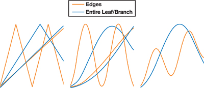
Figure 16-3 Wave Composition
Example 16-1. Functions Used for Wave Generation
float4 SmoothCurve(float4 x) { return x * x * (3.0 - 2.0 * x); }
float4 TriangleWave(float4 x) { return abs(frac(x + 0.5) * 2.0 - 1.0); }
float4 SmoothTriangleWave(float4 x) { return SmoothCurve(TriangleWave(x)); }
Detail Bending
Leaves' bending, as we have mentioned, is done by deforming the edges, using the vertex color's red channel for controlling edge stiffness control. This deformation is done along the world-space vertex normal xy direction.
Finally, we come to per-leaf bending, which we produce simply by deforming up and down along the z-axis, using the blue channel for leaf stiffness.
The vertex color's green channel contains a per-leaf phase variation, which we use to give each individual leaf its own phase, so that every leaf moves differently. Listing 16-2 shows the code for our detail-bending approach.
Leaves' shape and the number of vertices can vary depending on the vegetation type. For example, we model an entire leaf for a palm tree, which gives us the ability to nicely animate it in a very controllable way. For bigger trees, however, we model the leaves as several planes; we accept that total control is not possible, because several leaves can be on a relatively low-polygon-count plane placed as a texture. Still, we use the same approach for all different cases with good results.
Main Bending
We accomplish the main vegetation bending by displacing vertices' xy positions along the wind direction, using normalized height to scale the amount of deformation. Performing a simple displace is not enough, because we need to restrict vertex movement to minimize deformation artifacts. We achieve this by computing the vertex's distance to the mesh center and using this distance for rescaling the new displaced normalized position.
This process results in a spherical limited movement, which is enough for our vegetation case, because it is a single vegetation object. The amount of bending deformation needs to be carefully tweaked as well: too much bending will ruin the illusion. Listing 16-3 shows our implementation. Figure 16-4 shows some examples produced using this main bending technique.

Figure 16-4 Bending on Different Types of Vegetation
Example 16-2. The Implementation of Our Detail-Bending Approach
// Phases (object, vertex, branch)
float fObjPhase = dot(worldPos.xyz, 1);
fBranchPhase += fObjPhase;
float fVtxPhase = dot(
    vPos.xyz,
    fDetailPhase + fBranchPhase); // x is used for edges; y is used for branches
float2 vWavesIn =
    fTime +
    float2(fVtxPhase,
           fBranchPhase); // 1.975, 0.793, 0.375, 0.193 are good frequencies
float4 vWaves =
    (frac(vWavesIn.xxyy * float4(1.975, 0.793, 0.375, 0.193)) * 2.0 - 1.0) *
    fSpeed * fDetailFreq;
vWaves = SmoothTriangleWave(vWaves);
float2 vWavesSum =
    vWaves.xz + vWaves.yw; // Edge (xy) and branch bending (z) vPos.xyz +=
// vWavesSum.xxy * float3(fEdgeAtten * fDetailAmp *
vNormal.xy, fBranchAtten * fBranchAmp);
Example 16-3. The Main Bending Implementation
// Bend factor - Wind variation is done on the CPU.
float fBF = vPos.z * fBendScale; // Smooth bending factor and increase its
// nearby height limit. fBF += 1.0; fBF *= fBF;
// fBF = fBF * fBF - fBF; // Displace position
float3 vNewPos = vPos;
vNewPos.xy +=
    vWind.xy * fBF; // Rescale vPos.xyz = normalize(vNewPos.xyz)* fLength;
16.2 Vegetation Shading
We have thousands of different vegetation objects in Crysis, often covering the entire screen. So we needed to keep in mind a quality/efficiency ratio.
For this reason, we combined per-pixel shading with vertex shading, and in the case of grass, it's handled the exact same way. The only difference is that we do all shading pervertex due to grass's heavy fill-rate requirements.
Trunk shading is handled using standard Lambert and Phong shading models.
Foliage is approached in a different way. We render it as double-sided, and leaves use alpha test while grass uses alpha blending. We tried different approaches at the beginning of our project, such as a two-pass alpha test/blending, but for our case, the quality/efficiency ratio was not worth it.
In reality, foliage can have different thicknesses (for our foliage, that is the assumption we always make) and lets variable amounts of light pass through in different areas. Therefore, we needed a subsurface-scattering approximation.
We approximate this term by using an artist-made subsurface texture map, as shown in Figure 16-5, which is created using a regular image-editing software package. This map can have internal depth leaves' details such as veins and internal branches, and it can be relatively low-res (for example, 128 x 128), depending on the detail required. Listing 16-4 in Section 16.2.4 provides implementation details.
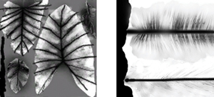
Figure 16-5 Examples of the Subsurface Texture Map
Because performance and quality for vegetation were crucial, for this case we decided to use a cheap and artist-friendly subsurface-scattering approximation that is computed per-vertex, simply using - N · L multiplied with light position visibility, E · L (the eye vector dot product with the light vector), both multiplied by subsurface texture for thickness variation. Figure 16-6 shows some examples.

Figure 16-6 Visualization of the Subsurface-Scattering Approximation
It is worth mentioning also that all shading in CryENGINE 2 is done in world space, which in our particular solution, helped to work around hardware limits for the attributebased instancing case and minimized shading discontinuities in some specific cases.
16.2.1 Ambient Lighting
Traditional constant ambient color looks very boring and has become outdated. At the beginning of development, we had two different vegetation shaders. One ended up being the implementation we describe in this chapter; the other was more complex, using spherical harmonics for indirect lighting, which was used mainly for big trees. To decrease the number of shader permutations and because of the complexity of spherical harmonics, we unfortunately had to drop this latter approach in favor of a unified and cheaper outdoor ambient-lighting solution.
Ambient lighting in our engine now has three variations: outdoor, indoor, and a simple solution for low-spec hardware. The way we handle outdoor and indoor ambient lighting is quite complex and would require two more chapters to explain; therefore, it's outside this chapter's scope.
All three variations try to give an interesting look to unlit surfaces, and for this chapter, we'll assume the low-spec hardware solution, which is implemented using hemisphere lighting (Taylor 2001) to break the flat look on shadowed areas.
Finally we also use a precomputed ambient occlusion term stored in the vertex's alpha channel, which is painted by artists or computed using standard 3D modeling software.
16.2.2 Edge Smoothing
One big issue when using alpha testing is the hard edges. At the time we developed vegetation main shading, there was no alpha-to-coverage support in any hardware (we do now support it as well). So we came up with a special solution to smooth out the edges through post-processing.
In CryENGINE 2, we use a deferred rendering approach, by first rendering a z-pass and writing depth into a floating-point texture.
This technique enables a wide range of effects (Wenzel 2007), which require depth information. Edge smoothing is one such effect; it works by doing edge detection using the depth texture and then using rotated triangle samples for dependent texture lookups using bilinear filtering. Edge smoothing works only on opaque geometry, however, because nonopaque geometry doesn't write depth into the z-target. Figure 16-7 shows how beneficial edge smoothing can be.
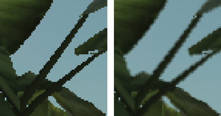
Figure 16-7 The Benefits of Edge Smoothing
16.2.3 Putting It All Together
The final results are achieved with the help of high-quality shadows together with an exponential tone mapper and various post-processing methods, such as bloom (Kawase 2004) and sun shafts, among others. Thanks to the combination of all these techniques, we achieve the final, in-game image quality we desire, as shown in Figure 16-8.
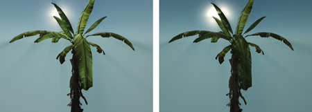
Figure 16-8 The Final Result
16.2.4 Implementation Details
Before showing the shader implementation, we would point out that a unified shader library solution was developed for CryENGINE 2 that not only simplified shaders, but also made them more readable and easier to maintain. It also added the extra benefit of enforcing naming conventions and minimizing code duplication.
The idea was simply to share as much as possible and minimize users' interaction with the shading kernel. As a result, all lights management, ambient computation, and other important computations (such as parallax occlusion mapping or decals) are hidden from shader writers.
Users have access to four custom functions, which allow them to initialize custom data, do per-light computations, ambient lighting, and shading finalization. Everything else is handled as a black box, which gives users important data for each of the four functions through a unified data structure. This data structure contains important shareable data, such as eye vector, normal vector, diffuse map color, bump map color, alpha, and so on.
Listings 16-4 and 16-5 show the final shader implementations. The functions in Listing 16-5 are the user custom functions, where we do the per-light source shading computation and apply light properties such as light diffuse and specular color. The ambient function is where we do the hemisphere lighting approximation. At the end of the listing, the shading final composition is where material properties such as diffuse texture, diffuse color, and specular color are applied.
Example 16-4. Functions Used for Shading Leaves' Back and Front Sides
half3 LeafShadingBack(half3 vEye, half3 vLight, half3 vNormal, half3 cDiffBackK,
                      half fBackViewDep)
{
  half fEdotL = saturate(dot(vEye.xyz, -vLight.xyz));
  half fPowEdotL = fEdotL * fEdotL;
  fPowEdotL *= fPowEdotL;
  // Back diffuse shading, wrapped slightly
  half fLdotNBack = saturate(dot(-vNormal.xyz, vLight.xyz) * 0.6 + 0.4);
  // Allow artists to tweak view dependency.
  half3 vBackShading = lerp(fPowEdotL, fLdotNBack, fBackViewDep);
  // Apply material back diffuse color.
  return vBackShading * cDiffBackK.xyz;
}
void LeafShadingFront(half3 vEye, half3 vLight, half3 vNormal, half3 cDifK,
                      half4 cSpecK, out half3 outDif, out half3 outSpec)
{
  half fLdotN = saturate(dot(vNormal.xyz, vLight.xyz));
  outDif = fLdotN * cDifK.xyz;
  outSpec = Phong(vEye, vLight, cSpecK.w) * cSpecK.xyz;
}
Example 16-5. Pixel Shader Code for Vegetation
void frag_custom_per_light(inout fragPass pPass, inout fragLightPass pLight)
{
  half3 cDiffuse = 0, cSpecular = 0;
  LeafShadingFront(pPass.vReflVec, pLight.vLight, pPass.vNormal.xyz,
                   pLight.cDiffuse.xyz, pLight.cSpecular, cDiffuse, cSpecular);
  // Shadows * light falloff * light projected texture
  half3 cK = pLight.fOcclShadow * pLight.fFallOff * pLight.cFilter;
  // Accumulate results.
  pPass.cDiffuseAcc += cDiffuse * cK;
  pPass.cSpecularAcc += cSpecular * cK;
  pPass.pCustom.fOcclShadowAcc += pLight.fOcclShadow;
}
void frag_custom_ambient(inout fragPass pPass, inout half3 cAmbient)
{
  // Hemisphere lighting approximation
  cAmbient.xyz =
      lerp(cAmbient * 0.5f, cAmbient, saturate(pPass.vNormal.z * 0.5f + 0.5f));
  pPass.cAmbientAcc.xyz = cAmbient;
}
void frag_custom_end(inout fragPass pPass, inout half3 cFinal)
{
  if (pPass.nlightCount && pPass.pCustom.bLeaves)
  {
    // Normalize shadow accumulation.
    half fOccFactor = pPass.pCustom.fOcclShadowAcc / pPass.nlightCount;
    // Apply subsurface map.
    pPass.pCustom.cShadingBack.xyz *= pPass.pCustom.cBackDiffuseMap;
    // Apply shadows and light projected texture.
    pPass.pCustom.cShadingBack.xyz *= fOccFactor * pPass.pCustom.cFilterColor;
  } // Apply diffuse texture and material diffuse color to
  // ambient/diffuse/sss terms. cFinal.xyz = (pPass.cAmbientAcc.xyz +
  // pPass.cDiffuseAcc.xyz +
pPass.pCustom.cShadingBack.xyz) *
pPass.cDiffuseMap.xyz * MatDifColor.xyz; // Apply gloss map and material specular color, add to result. cFinal.xyz += pPass.cSpecularAcc.xyz * pPass.cGlossMap.xyz *
MatSpecColor.xyz; // Apply prebaked ambient occlusion term. cFinal.xyz *=
                  // pPass.pCustom.fAmbientOcclusion; }
16.3 Conclusion
In this chapter, we have presented a snapshot of how the vegetation shading and procedural animation in Crysis is done, at the time this chapter was written. CryENGINE 2 evolves at such rapid pace that improvements might be added before Crysis is finished.
The presented procedural animation technique was implemented in a general way, so it is possible to apply wind forces even to nonvegetation objects, such as cloth and hair; the only difference is that no main bending is used for these cases.
We can have helicopters, grenade explosions, and even weapon fire affecting vegetation, cloth, and hair, all in an extremely efficient way.
As much as we pushed the envelope on vegetation rendering, there's still a lot of room for improvement as hardware gets faster. For example, shading could be improved, the leaves' specular lighting in most cases is not isotropic, and we could also use a more accurate subsurface-scattering approximation computed per-pixel. Finally, using more waves for bending would expand the range of the animation variation.
16.4 References
Baer, M. 2005. "Effects in Madagascar: Escape from Realism." Presentation at Eurographics 2005. More information available online at http://isg.cs.tcd.ie/eg2005/IS1.html.
Bourke, P. 1999. "Interpolation Methods." Available online at http://local.wasp.uwa.edu.au/~pbourke/other/interpolation/index.html.
Green, Simon. 2004. "Real-Time Approximations to Subsurface Scattering" In GPU Gems, edited by Randima Fernando, pp. 263–278. Addison-Wesley.
Kawase, M. 2004. "Practical Implementation of High Dynamic Range Rendering." Presentation at Game Developers Conference 2004. Available online at http://www.daionet.gr.jp/~masa/column/2004-04-04.html.
NVIDIA Corporation. 2005. "GPU Programming Exposed: The Naked Truth Behind NVIDIA's Demos." Presentation at SIGGRAPH 2005. Available online at http://http.download.nvidia.com/developer/presentations/2005/SIGGRAPH/Truth_About_NVIDIA_Demos_Med.pdf.
Taylor, P. 2001. "Per-Pixel Lighting." Online article available at http://msdn2.microsoft.com/en-us/library/ms810494.aspx.
Wenzel, C. 2007. "Real-Time Atmospheric Effects in Games Revisited." Presentation at Game Developers Conference 2007. Available online at http://ati.amd.com/developer/gdc/2007/D3DTutorial_Crytek.pdf.
The wind technique presented was partially inspired by the movie Madagascar and the artist-oriented presentation done by Matt Baer of DreamWorks Animation SKG at Eurographics 2005 (Baer 2005). Unfortunately, Baer 2005 seems not to be available anywhere online.
A special thanks to Marco Corbetta and Martin Mittring for helping me review and improve this chapter, and to everyone on Crytek's R&D team involved in vegetation rendering.
- Contributors
- Foreword
- Part I: Geometry
-
- Chapter 1. Generating Complex Procedural Terrains Using the GPU
- Chapter 2. Animated Crowd Rendering
- Chapter 3. DirectX 10 Blend Shapes: Breaking the Limits
- Chapter 4. Next-Generation SpeedTree Rendering
- Chapter 5. Generic Adaptive Mesh Refinement
- Chapter 6. GPU-Generated Procedural Wind Animations for Trees
- Chapter 7. Point-Based Visualization of Metaballs on a GPU
- Part II: Light and Shadows
-
- Chapter 8. Summed-Area Variance Shadow Maps
- Chapter 9. Interactive Cinematic Relighting with Global Illumination
- Chapter 10. Parallel-Split Shadow Maps on Programmable GPUs
- Chapter 11. Efficient and Robust Shadow Volumes Using Hierarchical Occlusion Culling and Geometry Shaders
- Chapter 12. High-Quality Ambient Occlusion
- Chapter 13. Volumetric Light Scattering as a Post-Process
- Part III: Rendering
-
- Chapter 14. Advanced Techniques for Realistic Real-Time Skin Rendering
- Chapter 15. Playable Universal Capture
- Chapter 16. Vegetation Procedural Animation and Shading in Crysis
- Chapter 17. Robust Multiple Specular Reflections and Refractions
- Chapter 18. Relaxed Cone Stepping for Relief Mapping
- Chapter 19. Deferred Shading in Tabula Rasa
- Chapter 20. GPU-Based Importance Sampling
- Part IV: Image Effects
-
- Chapter 21. True Impostors
- Chapter 22. Baking Normal Maps on the GPU
- Chapter 23. High-Speed, Off-Screen Particles
- Chapter 24. The Importance of Being Linear
- Chapter 25. Rendering Vector Art on the GPU
- Chapter 26. Object Detection by Color: Using the GPU for Real-Time Video Image Processing
- Chapter 27. Motion Blur as a Post-Processing Effect
- Chapter 28. Practical Post-Process Depth of Field
- Part V: Physics Simulation
-
- Chapter 29. Real-Time Rigid Body Simulation on GPUs
- Chapter 30. Real-Time Simulation and Rendering of 3D Fluids
- Chapter 31. Fast N-Body Simulation with CUDA
- Chapter 32. Broad-Phase Collision Detection with CUDA
- Chapter 33. LCP Algorithms for Collision Detection Using CUDA
- Chapter 34. Signed Distance Fields Using Single-Pass GPU Scan Conversion of Tetrahedra
- Chapter 35. Fast Virus Signature Matching on the GPU
- Part VI: GPU Computing
-
- Chapter 36. AES Encryption and Decryption on the GPU
- Chapter 37. Efficient Random Number Generation and Application Using CUDA
- Chapter 38. Imaging Earth's Subsurface Using CUDA
- Chapter 39. Parallel Prefix Sum (Scan) with CUDA
- Chapter 40. Incremental Computation of the Gaussian
- Chapter 41. Using the Geometry Shader for Compact and Variable-Length GPU Feedback
- Preface