
GPU Gems 3
GPU Gems 3 is now available for free online!
The CD content, including demos and content, is available on the web and for download.
You can also subscribe to our Developer News Feed to get notifications of new material on the site.
Chapter 13. Volumetric Light Scattering as a Post-Process
Kenny Mitchell
Electronic Arts
In this chapter, we present a simple post-process method that produces the effect of volumetric light scattering due to shadows in the atmosphere. We improve an existing analytic model of daylight scattering to include the effect of volumetric occlusion, and we present its implementation in a pixel shader. The demo, which is included on the DVD accompanying this book, shows the technique can be applied to any animating image of arbitrary scene complexity. A screenshot from the demo appears in Figure 13-1.
)
Figure 13-1 Volumetric Light Scattering on a Highly Animated Scene in Real Time
13.1 Introduction
In the real world, we rarely see things in a vacuum, where nothing exists between an object and its observer. In real-time rendering, the effect of participating media on light transport is often subject to low-complexity homogeneous assumptions. This is due to the intractable nature of the radiative transport equation (Jensen and Christensen 1998), accounting for emission, absorption, and scattering, in a complex interactive animated environment. In this chapter, we consider the effect of volumetric shadows in the atmosphere on light scattering, and we show how this effect can be computed in real time with a GPU pixel shader post-process applied to one or more image light sources.
13.10 References
Dobashi, Y., T. Yamamoto, and T. Nishita. 2002. "Interactive Rendering of Atmospheric Scattering Effects Using Graphics Hardware." Graphics Hardware.
Hoffman, N., and K. Mitchell. 2002. "Methods for Dynamic, Photorealistic Terrain Lighting." In Game Programming Gems 3, edited by D. Treglia, pp. 433–443. Charles River Media.
Hoffman, N., and A. Preetham. 2003. "Real-Time Light-Atmosphere Interactions for Outdoor Scenes." In Graphics Programming Methods, edited by Jeff Lander, pp. 337–352. Charles River Media.
James, R. 2003. "True Volumetric Shadows." In Graphics Programming Methods, edited by Jeff Lander, pp. 353–366. Charles River Media.
Jensen, H. W., and P. H. Christensen. 1998. "Efficient Simulation of Light Transport in Scenes with Participating Media Using Photon Maps." In Proceedings of SIGGRAPH 98, pp. 311–320.
Karras, T. 1997. Drain by Vista. Abduction'97. Available online at http://www.pouet.net/prod.php?which=418&page=0.
Max, N. 1986. "Atmospheric Illumination and Shadows." In Computer Graphics (Proceedings of SIGGRAPH 86) 20(4), pp. 117–124.
Mech, R. 2001. "Hardware-Accelerated Real-Time Rendering of Gaseous Phenomena." Journal of Graphics Tools 6(3), pp. 1–16.
Mitchell, J. 2004. "Light Shafts: Rendering Shadows in Participating Media." Presentation at Game Developers Conference 2004.
Nishita, T., Y. Miyawaki, and E. Nakamae. 1987. "A Shading Model for Atmospheric Scattering Considering Luminous Intensity Distribution of Light Sources." In Computer Graphics (Proceedings of SIGGRAPH 87) 21(4), pp. 303–310.
13.2 Crepuscular Rays
Under the right conditions, when a space contains a sufficiently dense mixture of light scattering media such as gas molecules and aerosols, light occluding objects will cast volumes of shadow and appear to create rays of light radiating from the light source. These phenomena are variously known as crepuscular rays, sunbeams, sunbursts, star flare, god rays, or light shafts. In sunlight, such volumes are effectively parallel but appear to spread out from the sun in perspective.
Rendering crepuscular rays was first tackled in non-real-time rendering using a modified shadow volume algorithm (Max 1986) and shortly after that, an approach was developed for multiple light sources (Nishita et al. 1987). This topic was revisited in real-time rendering, using a slice-based volume-rendering technique (Dobashi et al. 2002) and more recently applied using hardware shadow maps (Mitchell 2004). However, slice-based volume-rendering methods can exhibit sampling artifacts, demand high fill rate, and require extra scene setup. While a shadow-map method increases efficiency, here it also has the slice-based detractors and requires further video memory resources and rendering synchronization. Another real-time method, based on the work of Radomir Mech (2001), uses polygonal volumes (James 2003), in which overlapping volumes are accumulated using frame-buffer blending with depth peeling. A similar method (James 2004) removes the need for depth peeling using accumulated volume thickness. In our approach, we apply a per-pixel post-processing operation that requires no preprocessing or other scene setup, and which allows for detailed light shafts in animating scenes of arbitrary complexity.
In previous work (Hoffman and Preetham 2003), a GPU shader for light scattering in homogeneous media is implemented. We extend this with a post-processing step to account for volumetric shadows. The basic manifestation of this post-process can be traced to an image-processing operation, radial blur, which appears in many CG demo productions (Karras 1997). Although such demos used software rasterization to apply a post-processing effect, we use hardware-accelerated shader post-processing to permit more sophisticated sampling based on an analytic model of daylight.
13.3 Volumetric Light Scattering
To calculate the illumination at each pixel, we must account for scattering from the light source to that pixel and whether or not the scattering media is occluded. In the case of sunlight, we begin with our analytic model of daylight scattering (Hoffman and Preetham 2003). Recall the following:
Equation 1
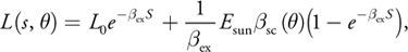
where s is the distance traveled through the media and is the angle between the ray and the sun. E sun is the source illumination from the sun, ex is the extinction constant composed of light absorption and out-scattering properties, and sc is the angular scattering term composed of Rayleigh and Mie scattering properties. The important aspect of this equation is that the first term calculates the amount of light absorbed from the point of emission to the viewpoint and the second term calculates the additive amount due to light scattering into the path of the view ray. As in Hoffman and Mitchell 2002, the effect due to occluding matter such as clouds, buildings, and other objects is modeled here simply as an attenuation of the source illumination,
Equation 2

where D() is the combined attenuated sun-occluding objects' opacity for the view location .
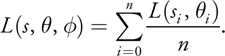
This consideration introduces the complication of determining the occlusion of the light source for every point in the image. In screen space, we don't have full volumetric information to determine occlusion. However, we can estimate the probability of occlusion at each pixel by summing samples along a ray to the light source in image space. The proportion of samples that hit the emissive region versus those that strike occluders gives us the desired percentage of occlusion, D(). This estimate works best where the emissive region is brighter than the occluding objects. In Section 13.5, we describe methods for dealing with scenes in which this contrast is not present.
If we divide the sample illumination by the number of samples, n, the post-process simply resolves to an additive sampling of the image:
Equation 3
13.3.1 Controlling the Summation
In addition, we introduce attenuation coefficients to parameterize control of the summation:
Equation 4
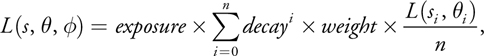
where exposure controls the overall intensity of the post-process, weight controls the intensity of each sample, and decayi (for the range [0, 1]) dissipates each sample's contribution as the ray progresses away from the light source. This exponential decay factor practically allows each light shaft to fall off smoothly away from the light source.
The exposure and weight factors are simply scale factors. Increasing either of these increases the overall brightness of the result. In the demo, the sample weight is adjusted with fine-grain control and the exposure is adjusted with coarse-grain control.
Because samples are derived purely from the source image, semitransparent objects are handled with no additional effort. Multiple light sources can be applied through successive additive screen-space passes for each ray-casting light source. Although in this explanation we have used our analytic daylight model, in fact, any image source may be used.
For the sun location, , and each screen-space image location, , we implement the summation with successive samples from the source image at regular intervals along the ray vector, = (-)/n(density). Here we introduce density to permit control over the separation between samples for cases in which we wish to reduce the overall number of sample iterations while retaining a sufficiently alias-free sampling density. If we increase the density factor, we decrease the separation between samples, resulting in brighter light shafts covering a shorter range.
In Figure 13-2, no samples from 1 are occluded, resulting in maximum scattering illumination under regular evaluation of L(s,). At 2, a proportion of samples along the ray hit the building, and so less scattering illumination is accumulated. By summing over cast rays for each pixel in the image, we generate volumes containing occluded light scattering.
)
Figure 13-2 Ray Casting in Screen Space
We may reduce the bandwidth requirements by downsampling the source image. With filtering, this reduces sampling artifacts and consequently introduces a local scattering contribution by neighborhood sampling due to the filter kernel. In the demo, a basic bilinear filter is sufficient.
13.4 The Post-Process Pixel Shader
The core of this technique is the post-process pixel shader, given in Listing 13-1, which implements the simple summation of Equation 4.
Given the initial image, sample coordinates are generated along a ray cast from the pixel location to the screen-space light position. [1] The light position in screen space is computed by the standard world-view-project transform and is scaled and biased to obtain coordinates in the range [-1, 1]. Successive samples L(s, , i ) in the summation of Equation 4 are scaled by both the weight constant and the exponential decay attenuation coefficients for the purpose of parameterizing control of the effect. The separation between samples' density may be adjusted and as a final control factor, the resulting combined color is scaled by a constant attenuation coefficient exposure.
Example 13-1. Post-Process Shader Implementation of Additive Sampling
float4 main(float2 texCoord : TEXCOORD0) : COLOR0
{
  // Calculate vector from pixel to light source in screen space.
  half2 deltaTexCoord = (texCoord - ScreenLightPos.xy);
  // Divide by number of samples and scale by control factor.
  deltaTexCoord *= 1.0f / NUM_SAMPLES * Density;
  // Store initial sample.
  half3 color = tex2D(frameSampler, texCoord);
  // Set up illumination decay factor.
  half illuminationDecay = 1.0f;
  // Evaluate summation from Equation 3 NUM_SAMPLES iterations.
  for (int i = 0; i < NUM_SAMPLES; i++)
  {
    // Step sample location along ray.
    texCoord -= deltaTexCoord;
    // Retrieve sample at new location.
    half3 sample = tex2D(frameSampler, texCoord);
    // Apply sample attenuation scale/decay factors.
    sample *= illuminationDecay * Weight;
    // Accumulate combined color.
    color += sample;
    // Update exponential decay factor.
    illuminationDecay *= Decay;
  }
  // Output final color with a further scale control factor.
  return float4(color * Exposure, 1);
}
13.5 Screen-Space Occlusion Methods
As stated, sampling in screen space is not a pure occlusion sampling. Undesirable streaks may occur due to surface texture variations. Fortunately, we can use the following measures to deal with these undesirable effects.
13.5.1 The Occlusion Pre-Pass Method
If we render the occluding objects black and untextured into the source frame buffer, image processing to generate light rays is performed on this image. Then the occluding scene objects are rendered with regular shading, and the post-processing result is additively blended into the scene. This approach goes hand in hand with the common technique of rendering an unshaded depth pre-pass to limit the depth complexity of fully shaded pixels. Figure 13-3 shows the steps involved.
)
Figure 13-3 The Effect of the Occlusion Pre-Pass
13.5.2 The Occlusion Stencil Method
On earlier graphics hardware the same results can be achieved without a pre-pass by using a stencil buffer or alpha buffer. The primary emissive elements of the image (such as the sky) are rendered as normal while simultaneously setting a stencil bit. Then the occluding scene objects are rendered with no stencil bit. When it comes to applying the post-process, only those samples with the stencil bit set contribute to the additive blend.
13.5.3 The Occlusion Contrast Method
Equally though, this problem may be managed by reducing texture contrast through the texture's content, fog, aerial perspective, or light adaption as the intensity of the effect increases when facing the light source. Anything that reduces the illumination frequency and contrast of the occluding objects diminishes streaking artifacts.
13.6 Caveats
Although compelling results can be achieved, this method is not without limitations. Light shafts from background objects can appear in front of foreground objects, when dealing with relatively near light sources, as shown in Figure 13-4. In a full radiative transfer solution, the foreground object would correctly obscure the background shaft. One reason this is less noticeable than expected is that it can be perceived as the manifestation of a camera lens effect, in which light scattering occurs in a layer in front of the scene. This artifact can also be reduced in the presence of high-frequency textured objects.
)
Figure 13-4 Dealing with One Limitation
As occluding objects cross the image's boundary, the shafts will flicker, because they are beyond the range of visible samples. This artifact may be reduced by rendering an extended region around the screen to increase the range of addressable samples.
Finally, when facing perpendicular to the source, the light's screen-space location can tend toward infinity and therefore lead to large separation between samples. This can be diminished by clamping the screen-space location to an appropriate guard-band region. Alternatively, the effect can be faded toward the perpendicular and is further decreased when using an occlusion method.
13.7 The Demo
The demo on this book's DVD uses Shader Model 3.0 to apply the post-process, because the number of texture samples needed exceeds the limits of Shader Model 2.0. However, the effect has been implemented almost as efficiently with earlier graphics hardware by using additive frame-buffer blending over multiple passes with a stencil occlusion method, as shown in Figure 13-5.
)
Figure 13-5 Crepuscular Rays with Multiple Additive Frame-Buffer Passes on Fixed-Function Hardware
13.8 Extensions
Sampling may occur at a lower resolution to reduce texture bandwidth requirements. A further enhancement is to vary the sample pattern with stochastic sampling, thus reducing regular pattern artifacts where sampling density is reduced.
Our method performs the post-process in a single-pass execution of a shader. In one multipass approach, the pixel shader summation may be performed where the results of concentric rectangular bands emanating from the light source may be accumulated into successive outer bands, where L(s, , ) = Li - 1(s, , ) + Li (s, , ). While this may not be most suited to current hardware design, this approach is the minimal required sampling and computation limit.
Creating a balance between light shaft intensity and avoiding oversaturation requires adjustments of the attenuation coefficients. An analytic formula that performs light adaption to a consistent image tone balance may yield an automatic method for obtaining a consistently perceived image. For example, perhaps we can evaluate a combination of average, minimum, and maximum illumination across the image and then apply a corrective color ramp, thus avoiding excessive image bloom or gloominess.
13.9 Summary
We have shown a simple post-process method that produces the effect of volumetric light scattering due to shadows in the atmosphere. We have expanded an existing analytic model of daylight scattering to include the contribution of volumetric occlusion, and we have described its implementation in a pixel shader. The demo shows that this is a practical technique that can be applied to any animating image of arbitrary scene complexity.
- Contributors
- Foreword
- Part I: Geometry
-
- Chapter 1. Generating Complex Procedural Terrains Using the GPU
- Chapter 2. Animated Crowd Rendering
- Chapter 3. DirectX 10 Blend Shapes: Breaking the Limits
- Chapter 4. Next-Generation SpeedTree Rendering
- Chapter 5. Generic Adaptive Mesh Refinement
- Chapter 6. GPU-Generated Procedural Wind Animations for Trees
- Chapter 7. Point-Based Visualization of Metaballs on a GPU
- Part II: Light and Shadows
-
- Chapter 8. Summed-Area Variance Shadow Maps
- Chapter 9. Interactive Cinematic Relighting with Global Illumination
- Chapter 10. Parallel-Split Shadow Maps on Programmable GPUs
- Chapter 11. Efficient and Robust Shadow Volumes Using Hierarchical Occlusion Culling and Geometry Shaders
- Chapter 12. High-Quality Ambient Occlusion
- Chapter 13. Volumetric Light Scattering as a Post-Process
- Part III: Rendering
-
- Chapter 14. Advanced Techniques for Realistic Real-Time Skin Rendering
- Chapter 15. Playable Universal Capture
- Chapter 16. Vegetation Procedural Animation and Shading in Crysis
- Chapter 17. Robust Multiple Specular Reflections and Refractions
- Chapter 18. Relaxed Cone Stepping for Relief Mapping
- Chapter 19. Deferred Shading in Tabula Rasa
- Chapter 20. GPU-Based Importance Sampling
- Part IV: Image Effects
-
- Chapter 21. True Impostors
- Chapter 22. Baking Normal Maps on the GPU
- Chapter 23. High-Speed, Off-Screen Particles
- Chapter 24. The Importance of Being Linear
- Chapter 25. Rendering Vector Art on the GPU
- Chapter 26. Object Detection by Color: Using the GPU for Real-Time Video Image Processing
- Chapter 27. Motion Blur as a Post-Processing Effect
- Chapter 28. Practical Post-Process Depth of Field
- Part V: Physics Simulation
-
- Chapter 29. Real-Time Rigid Body Simulation on GPUs
- Chapter 30. Real-Time Simulation and Rendering of 3D Fluids
- Chapter 31. Fast N-Body Simulation with CUDA
- Chapter 32. Broad-Phase Collision Detection with CUDA
- Chapter 33. LCP Algorithms for Collision Detection Using CUDA
- Chapter 34. Signed Distance Fields Using Single-Pass GPU Scan Conversion of Tetrahedra
- Chapter 35. Fast Virus Signature Matching on the GPU
- Part VI: GPU Computing
-
- Chapter 36. AES Encryption and Decryption on the GPU
- Chapter 37. Efficient Random Number Generation and Application Using CUDA
- Chapter 38. Imaging Earth's Subsurface Using CUDA
- Chapter 39. Parallel Prefix Sum (Scan) with CUDA
- Chapter 40. Incremental Computation of the Gaussian
- Chapter 41. Using the Geometry Shader for Compact and Variable-Length GPU Feedback
- Preface