
GPU Gems 3
GPU Gems 3 is now available for free online!
The CD content, including demos and content, is available on the web and for download.
You can also subscribe to our Developer News Feed to get notifications of new material on the site.
Chapter 5. Generic Adaptive Mesh Refinement
Tamy Boubekeur
LaBRI–INRIA, University of Bordeaux
Christophe Schlick
LaBRI–INRIA, University of Bordeaux
In this chapter we present a single-pass generic vertex program for performing adaptive, on-the-fly refinement of meshes with arbitrary topology. Starting from a static or animated coarse mesh, this vertex program replaces each triangle with a refined triangular patch, chosen according to the required amount of local geometry refinement, among a set of pre-tessellated patterns stored in GPU memory. By encoding these patterns in parametric space, this one-to-many, on-the-fly triangle substitution is cast as a simple barycentric interpolation of a vertex displacement function, which is either user-provided or computed from existing data. In addition to vertex displacement, the same process can further be used to interpolate any other per-vertex attribute during the refinement process. The method is totally generic in the sense that no restriction is ever made about the mesh topology, the displacement function, or the refinement level.
Several illustrative applications are presented here, including full GPU implementations of (1) mesh smoothing with higher-order Bézier patches, (2) high-frequency geometry synthesis with procedural displacement functions, (3) animated free-form deformations, (4) standard displacement mapping with guaranteed shading and silhouette consistency, and (5) multilevel terrain rendering, to name only a few. But the technique is virtually applicable to any problem that uses predictable generation of geometry by refinement.
5.1 Introduction
Mesh refinement is a powerful technique for representing 3D objects with complex shapes. Rather than enumerate the huge number of polygons that would be required to get an accurate discrete approximation of such a complex shape, mesh refinement techniques split the surface representation into a coarse polygonal mesh combined with a continuous displacement function. Then, at rendering time, two successive operations are basically performed on the coarse mesh:
- Tessellation, for generating a refined mesh topology at the desired level of detail
- Displacement, for translating each newly inserted vertex to its final position, obtained by sampling the continuous displacement function
More precisely, the role of the tessellation step is to split each polygon of the coarse mesh into a (possibly huge) set of small triangles without performing any actual geometric deformation. The role of the displacement step is to add small-scale geometric details by moving the vertices of these triangles along a vector provided by the displacement function. Depending on this function, the displacement of each vertex can either be constrained along its normal vector or be performed along an arbitrary vector. While the former solution is more compact and easier to apply on an animated object, the latter allows the creation of much more complex shapes for a given coarse mesh. Popular displacement methods include bitmap textures (such as grayscale height-fields) and procedural 3D textures (such as Perlin noise).
Many existing computer graphics techniques can be expressed under this paradigm, such as spline-based or wavelet-based surface representation, subdivision surfaces, hierarchical height fields, and more. However, performing a full GPU implementation of this two-stage process remains a problem with current devices. Although the traditional vertex shader allows an efficient computation of the displacement stage, the lack of geometry creation on the GPU makes the tessellation stage really tricky. Recently a geometry shader (Blythe 2006) has been designed for geometry upscale, but it suffers from a strong limitation, as it can output 1,024 floats at most, which means that only two or three levels of refinement can be applied on each triangle. If deeper refinement is required, multipass geometry shading has to be employed, which obviously reduces overall performance.
On the contrary, the vertex program proposed in this chapter allows very deep adaptive, single-pass mesh refinement even on three-generations-old GPUs. Basically, it relies on barycentric coordinates to perform a consistent, crack-free adaptive tessellation. One major advantage of such an on-the-fly implementation of mesh refinement is to deal only with low-resolution meshes at the CPU level, letting the GPU adaptively generate the high-resolution displaced meshes. With our method, this target mesh is never generated on the CPU, never transmitted on the graphics bus, and even never stored on the GPU; the only remaining bottleneck is the GPU's vertex-processing horsepower.
5.2 Overview
The generic adaptive mesh refinement (GAMeR) technique that we present in this chapter offers the following features:
- Standard geometry representations used by common rendering APIs (polygon soups or indexed triangle sets) can be employed as-is, without any preprocessing (such as global or local parameterization) and without any of the additional data structures often required by refinement techniques (such as half-edge structure).
- Only the coarse mesh is transmitted from the CPU to the GPU. The only additional data needed by GAMeR is a per-vertex scalar attribute, called depth tag, that indicates the level of detail required in the vicinity of each vertex. Note that this depth-tagging may be generated either automatically or under user supervision.
- Because the mesh refinement is performed on-the-fly, on a per-frame/per-triangle basis, arbitrary level of detail can be obtained, even for animated meshes.
- The whole two-stage adaptive mesh refinement (tessellation and displacement) is performed on the GPU by a single-pass vertex program, which totally frees the fragment shaders for including additional visual enrichments.
The workflow architecture used by GAMeR is presented in Figure 5-1. The key idea is to precompute all the possible refinement configurations of a single triangle, for various per-vertex depth tags, and encode them using barycentric coordinates. Each possible configuration is called an adaptive refinement pattern (ARP) and is stored once for all on the GPU, as a vertex buffer object. Then, at rendering time, the attributes of each polygon of the coarse mesh, as well as the attributes of the displacement function, are uploaded to the GPU (by using uniform variables, for instance) and the adequate ARP is chosen according to the depth tags. Finally, the vertex program simultaneously interpolates the vertices of the current coarse polygon, and the displacement function, by using the barycentric coordinates stored at each node of the ARP. The first interpolation generates the position of the node on the polygon (tessellation) and the second one translates the node to its final position (displacement).
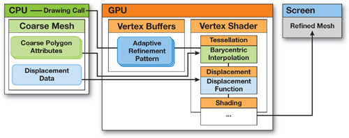
Figure 5-1 Workflow Architecture of Our Generic Adaptive Mesh Refinement
5.3 Adaptive Refinement Patterns
During the initialization step of GAMeR, all possible ARPs are computed once for all and stored in a 3D matrix, called the ARP pool, as shown in Figure 5-2a. An element {i, j, k} of this matrix is the ARP corresponding to a triangle refined at depth i on its first edge, depth j on the second edge, and depth k on the last one. Since depth values are stored on a per-vertex basis, the order in which the edges are enumerated does not matter. The diagonal of the matrix corresponds to the case of uniform refinement (all edges are refined at the same depth). All other cases have to deal with adaptive refinement, because each edge may require a different depth.
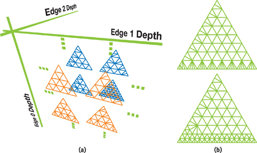
Figure 5-2 Adaptive Refinement Patterns
A simple, but not optimal, way to generate the ARP for a nonuniform depth-tag configuration is to uniformly refine the initial triangle until reaching the minimum depth of the three edges. Then, in the neighborhood of the remaining edges, the border triangles are simply split to reach the correct refinement depth for each edge. The upper pattern in Figure 5-2b has been obtained with this simple algorithm applied on the {3, 4, 5} depth-tag configuration. To get more equilateral triangles, a larger support for adaptive refinement may be employed. The lower pattern in Figure 5-2b shows an alternative topology for the same {3, 4, 5} configuration.
5.3.1 Implementation
As already mentioned, each node of the ARP is encoded by using its barycentric coordinates. The very valuable benefit of this approach is that only a single pattern is required for a given depth configuration, whatever the position, orientation, and shape of any coarse triangle it will substitute during the refinement step. Note, therefore, that in the vertex program, the barycentric coordinates of the refined vertices will take the place of the usual position (gl_Vertex). Thus, the geometric attributes of the coarse triangle have to be transmitted in another way. For deep enough refinements or recent graphics devices, uniform variables can be used safely with regard to performance.
The ARP is the central structure of our system. In order to achieve maximum performance at rasterization time, the ARP is encoded as an indexed vertex buffer of degenerated triangle strips, directly in the GPU memory. Moreover, because we use dyadic refinement, each refinement level is actually a superset of the previous one, so we can further reduce the global memory footprint by separating the geometry from the topology. A vertex buffer is used to encode all the geometry, as the set of barycentric coordinates for the nodes that belong to the deepest regular ARP. Then the topology of any given ARP is encoded by using an index buffer, as an indexed strip over this maximum configuration. So, at rendering time, the only action to perform is to bind the index buffer of the selected APR, while always keeping the same vertex buffer.
In restricted conditions, such as PDAs with 16-bit precision, this encoding allows a maximum refinement level of 256x256 for each coarse triangle. At the other extreme, with a modern GPU, we have experienced real-time performance when using 1024x1024 refinement per coarse triangle, in the context of procedural high-frequency geometry synthesis. Even higher resolutions can easily be obtained if required, because our kernel fully runs in object space and does not depend on the screen resolution.
5.4 Rendering Workflow
5.4.1 Depth-Tagging
The depth-tagging process provides an efficient and flexible solution to control the level of adaptive refinement of the input coarse mesh. At the CPU level, the application provides a per-vertex scalar attribute (a positive integer, in our implementation) that indicates the level of detail required in the vicinity of each vertex. In practice, common choices for computing the depth tag may include the camera-to-vertex distance, the local curvature, the semantic importance of the object, the saliency, or any combination of these values. Figure 5-3 presents two different mesh refinements generated by GAMeR on the same coarse mesh, by using either a distance-based tagging or a curvature-based one.
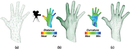
Figure 5-3 Adaptive GPU Refinement Control by Depth-Tagging
Note that, in some specific cases, the depth-tagging may also be performed at the GPU level, by using a preliminary rendering pass with render-to-vertex-buffer functionalities. However, we believe that this is usually not a good choice, mainly for two reasons:
- The depth-tagging is computed on the coarse mesh, which contributes little overhead at the CPU level.
- The depth-tagging may depend on various criteria, most of which are not easily available at the GPU level.
Once the depth-tagging has been performed, the attributes of each coarse polygon are uploaded as uniform variables, and the depth-tag configuration is used to select the adequate ARP's index buffer. Note that edges are not explicitly represented in most real-time 3D engines. Thus we compute depth tags on a per-vertex basis, and then we convert these values to per-edge depth tags simply by using the mean value of the two adjacent vertices. This ensures a crack-free transition between neighboring triangles.
5.4.2 The CPU-Level Rendering Loop
At the CPU level, the application just has to maintain the per-vertex depth tags, bind the adequate index buffer from the ARP pool, and draw it, as shown in Listing 5-1.
Example 5-1. Pseudocode for the Rendering Loop on the CPU
GLuint ARPPool[MaxDepth][MaxDepth][MaxDepth];
. . .
void render(Mesh M)
{
  if (dynamic)
  {
for each
  Vertex V of M do V.tag = computeRefinementDepth(V);
for each
  CoarseTriangle T of M do
  {
    sendToGPU(T.attributes);
    bind(ARPPool[T.v0.tag][T.v1.tag][T.v2.tag]);
    drawElement();
  }
  }
Note that the number of bind operations can be greatly reduced by clustering coarse triangles according to their depth-tag configuration. Similarly, displacement attributes (such as standard displacement maps, parameters of procedural functions, or coefficients for spline-based or wavelet-based smoothing) are either uploaded once for all at initialization, or on a per-frame basis in the case of animated displacement.
5.4.3 The GPU-Level Refinement Process
The vertex program contains three stages: (1) a tessellation stage, which simply interpolates the vertices of the coarse triangle; (2) a displacement stage, which samples and interpolates the continuous displacement function; and (3) the traditional shading stage. In Listing 5-2, we use simple linear interpolation for both stages, but higher-order interpolation can be used, with possibly different orders for each attribute (for example, linear interpolation for vertex positions, coupled with quadratic interpolation for normal vectors).
Example 5-2. Pseudocode of the Refinement Vertex Program on the GPU
const uniform vec3 p0, p1, p2, n0, n1, n2;
// User-defined Displacement Function float dispFunc(vec3 v) {. . .}
void main(void)
{
  // Tessellation by barycentric interpolation
  float u = gl_Vertex.y, v = gl_Vertex.z, w = gl_Vertex.x; // w=1-u-v
  gl_Vertex = vec4(p0 * w + p1 * u + p2 * v, gl_Vertex.w);
  gl_Normal = n0 * w + n1 * u + n2 * v;
  // User-defined Displacement Function
  float d = dispFunc(gl_Vertex.xyz);
  gl_Vertex += d * gl_Normal;
  // Shading and Output
...
}
5.5 Results
In this section, we present several examples created with GAMeR. Most of them use simple curvature-based and distance-based depth-tagging. Refinement depth ranges from 4 to 10 (that is, from 16x16 to 1024x1024 refined triangles). In Figure 5-4, a mesh smoothing is performed with triangular Bézier patches, using either curved PN triangles (Vlachos et al. 2001) or scalar tagged PN triangles (Boubekeur et al. 2005) to include additional sharp features. In this case, the displacement attributes transmitted on the graphics bus are reduced to a few Bézier parameters per coarse triangle.
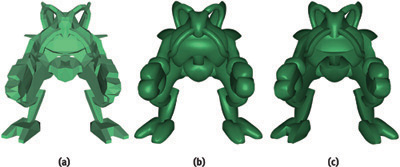
Figure 5-4 Mesh Smoothing
Figure 5-5 illustrates another interesting feature of our generic refinement method: because no conversion or preprocessing of the coarse input mesh is required, it can be animated in real time, while always being consistently refined.

Figure 5-5 Animated Surface Refinement
As shown on Figure 5-6, this flexibility also ensures a consistent adaptive refinement of a surface with arbitrary topologies.

Figure 5-6 Single-Pass Adaptive Refinement of Arbitrary Topologies
Another application of our refinement kernel is the use of procedural refinements. In this case, complex shapes can be represented as very simple meshes equipped with procedural functions. These functions may exhibit very high frequencies, requiring a deep level of tessellation for accurate sampling. Examples are shown in Figure 5-7.

Figure 5-7 Procedural Refinement
With the use of vertex texturing, displacement maps can also be used with our kernel. Figure 5-8a shows a terrain rendering system using our kernel for refining coarse ground in a view-dependent fashion while displacing it with a height map. Figures 5-8b and 5-8c show a displaced refinement of a scanned human face.
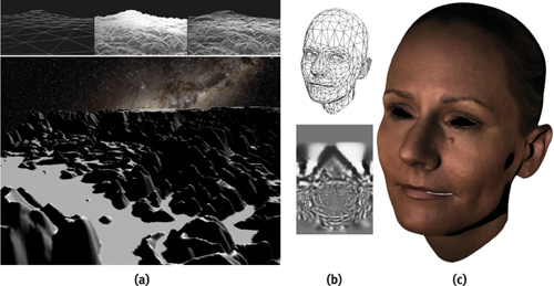
Figure 5-8 Adaptive GPU Mesh with Displacement Maps
In general, the best overall performance is obtained with the highest refined size versus coarse size ratio. The refinement can be about three orders of magnitude faster than its equivalent CPU implementation. With recent GPU unified architectures, vertex texture fetches can be performed very efficiently, which allows the use of more and more displacement maps in real-time applications. Our generic refinement technique is then a good candidate for saving CPU workload, graphics bus bandwidth, and on-board graphics memory. Table 5-1 illustrates the frame rates obtained by our implementation on an NVIDIA GeForce 8800 GTX for various models presented earlier.
Table 5-1. Frame Rates Achieved Using GAMeR
|
Model |
Input (CPU) (Triangles) |
Depth Tag |
Displacement |
Output (GPU) (Millions of Triangles) |
Frame Rate (FPS) |
|
Robot |
1,246 |
Curvature + Distance |
Bézier (STPN) |
1.1 |
263 |
|
Hand |
546 |
Distance |
Procedural |
2.1 |
155 |
|
Face |
1,914 |
Curvature |
Displacement Map |
4.0 |
58 |
|
Terrain |
98 |
Distance |
Height Map |
6.4 |
44 |
Globally, if the refinement depth is low and the input CPU mesh is large, the system is bottlenecked by the upload of coarse polygon attributes. At the other extreme, if the input CPU mesh is coarse and the refinement is deep, the system is bottlenecked only by the GPU horsepower. For instance, with a target mesh size of one million triangles, an input CPU mesh of 65,000 triangles results in an average GPU refinement depth of 2 and rendering performed at 38 frames/sec. With a CPU mesh of 4,000 triangles, the average GPU refinement depth is 4, and the rendering reaches 279 frames/sec. This makes the system particularly interesting for applications requiring a huge refinement depth, such as CAD or scientific visualization.
5.6 Conclusion and Improvements
We have presented an efficient single-pass vertex shading technique for performing real-time adaptive mesh refinement. This technique is particularly interesting when the input mesh is coarse and the refinement is deep. This technique can be combined with the geometry shader by using the geometry shader for low refinements (such as a depth of 1 or 2) and then switching to our kernel for deeper refinements. The tagging system makes our method generic and allows us to integrate it in a 3D engine by just adding a per-vertex attribute. The killer application of our method is clearly the case of dynamic coarse mesh (such as an animated character face or a soft body) equipped with a displacement function, where the CPU application just has to maintain the coarse mesh while still having very high resolution objects on screen.
Among the possible improvements of this technique, we can mention the use of alternative refinement patterns, with different polygons distribution, as well as the implementation of true subdivision surfaces, where the displacement function is based on their parametric form instead of their recursive definition.
5.7 References
Blythe, David. 2006. "The Direct3D 10 System." In ACM Transactions on Graphics (Proceedings of SIGGRAPH 2006) 25(3), pp. 724–734.
Bolz, Jeff, and Peter Schroder. 2003. "Evaluation of Subdivision Surfaces on Programmable Graphics Hardware." http://multires.caltech.edu/pubs/GPUSubD.pdf.
Boubekeur, Tamy, Patrick Reuter, and Christophe Schlick. 2005. "Scalar Tagged PN Triangle." Eurographics 2005.
Boubekeur, Tamy, and Christophe Schlick. 2005. "Generic Mesh Refinement on GPU." In Proceedings of the SIGGRAPH/Eurographics Workshop on Graphics Hardware 2005, pp. 99–104.
Boubekeur, Tamy, and Christophe Schlick. 2007. "A Flexible Kernel for Adaptive Mesh Refinement on GPU." Computer Graphics Forum, to appear.
Bunnell, Michael. 2005. "Adaptive Tessellation of Subdivision Surfaces with Displacement Mapping." In GPU Gems 2, edited by Matt Pharr, pp. 109–122. Addison-Wesley.
Shiue, Le-Jeng, Ian Jones, and Jorg Peters. 2005. "A Realtime GPU Subdivision Kernel." In ACM Transactions on Graphics (Proceedings of SIGGRAPH 2005) 24(3), pp. 1010–1015.
Vlachos, Alex, Jörg Peters, Chas Boyd, and Jason Michel. 2001. "Curved PN Triangles." In Proceedings of SIGGRAPH 2001 Symposium on Interactive 3D Graphics, pp. 159–166.
- Contributors
- Foreword
- Part I: Geometry
-
- Chapter 1. Generating Complex Procedural Terrains Using the GPU
- Chapter 2. Animated Crowd Rendering
- Chapter 3. DirectX 10 Blend Shapes: Breaking the Limits
- Chapter 4. Next-Generation SpeedTree Rendering
- Chapter 5. Generic Adaptive Mesh Refinement
- Chapter 6. GPU-Generated Procedural Wind Animations for Trees
- Chapter 7. Point-Based Visualization of Metaballs on a GPU
- Part II: Light and Shadows
-
- Chapter 8. Summed-Area Variance Shadow Maps
- Chapter 9. Interactive Cinematic Relighting with Global Illumination
- Chapter 10. Parallel-Split Shadow Maps on Programmable GPUs
- Chapter 11. Efficient and Robust Shadow Volumes Using Hierarchical Occlusion Culling and Geometry Shaders
- Chapter 12. High-Quality Ambient Occlusion
- Chapter 13. Volumetric Light Scattering as a Post-Process
- Part III: Rendering
-
- Chapter 14. Advanced Techniques for Realistic Real-Time Skin Rendering
- Chapter 15. Playable Universal Capture
- Chapter 16. Vegetation Procedural Animation and Shading in Crysis
- Chapter 17. Robust Multiple Specular Reflections and Refractions
- Chapter 18. Relaxed Cone Stepping for Relief Mapping
- Chapter 19. Deferred Shading in Tabula Rasa
- Chapter 20. GPU-Based Importance Sampling
- Part IV: Image Effects
-
- Chapter 21. True Impostors
- Chapter 22. Baking Normal Maps on the GPU
- Chapter 23. High-Speed, Off-Screen Particles
- Chapter 24. The Importance of Being Linear
- Chapter 25. Rendering Vector Art on the GPU
- Chapter 26. Object Detection by Color: Using the GPU for Real-Time Video Image Processing
- Chapter 27. Motion Blur as a Post-Processing Effect
- Chapter 28. Practical Post-Process Depth of Field
- Part V: Physics Simulation
-
- Chapter 29. Real-Time Rigid Body Simulation on GPUs
- Chapter 30. Real-Time Simulation and Rendering of 3D Fluids
- Chapter 31. Fast N-Body Simulation with CUDA
- Chapter 32. Broad-Phase Collision Detection with CUDA
- Chapter 33. LCP Algorithms for Collision Detection Using CUDA
- Chapter 34. Signed Distance Fields Using Single-Pass GPU Scan Conversion of Tetrahedra
- Chapter 35. Fast Virus Signature Matching on the GPU
- Part VI: GPU Computing
-
- Chapter 36. AES Encryption and Decryption on the GPU
- Chapter 37. Efficient Random Number Generation and Application Using CUDA
- Chapter 38. Imaging Earth's Subsurface Using CUDA
- Chapter 39. Parallel Prefix Sum (Scan) with CUDA
- Chapter 40. Incremental Computation of the Gaussian
- Chapter 41. Using the Geometry Shader for Compact and Variable-Length GPU Feedback
- Preface