
GPU Gems 3
GPU Gems 3 is now available for free online!
The CD content, including demos and content, is available on the web and for download.
You can also subscribe to our Developer News Feed to get notifications of new material on the site.
Chapter 3. DirectX 10 Blend Shapes: Breaking the Limits
Tristan Lorach
NVIDIA Corporation
Rich animation is an important aspect of any modern game, and blend shapes are among the most effective techniques to drive this animation. With the capabilities introduced in DirectX 10 hardware, prior GPU-based implementations can be extended to support much more flexible blending scenarios. In this chapter we present two strategies for moving beyond the previous limitations on GPU-accelerated implementations of blend shapes. Figure 3-1 illustrates several facial expressions created from multiple blend shapes.
)
Figure 3-1 This Character Has More Than 50 Blend Shapes
3.1 Introduction
Blend shapes are a well-known and useful deformer available in any digital content creation (DCC) application. These deformers can achieve rich animations by morphing the mesh between many different shapes. For this reason they are also known as morph targets (Beeson 2004).
Blend shapes are a very flexible tool, enabling many animation possibilities. A simpler animation sequence may use a series of poses through which the object is morphed. During a sequence such as this, the geometry is blended between only two of the targets at any instant in the animation. Alternatively, more-complex animations may combine several blend shapes to produce a new expression. On top of the opportunities for facial animation, blend shapes offer interesting possibilities in multiplayer games. Many of these games require that the character be configurable so that every individual can have a unique identity in the game. The blend shapes can be used to composite features to a mesh that is read back to the CPU for efficient processing, and they can also be used to produce variations in the animations for processing at runtime.
NVIDIA's past demo characters Dawn, Nalu, and Luna are examples of how blend shapes can be used to create facial expressions. Interactively changing the sliders controlling the expressions in these demos reveals that the flexibility is still restricted. The user can select only a base expression and use sliders to change some details of that base expression. These restrictions result from the limits on GPU capabilities when the demos were created.
GPUs prior to the NVIDIA GeForce 8800 required the additional blend shape data to be sent as vertex attributes. The limited number of attributes restricted the number of blend shapes the GPU could process simultaneously. This restriction led to a necessary trade-off: either the blend shapes were processed on the CPU (potentially bottlenecking the application), or the blend shapes were processed on the GPU, with restrictions on the flexibility of the animation.
When the Dawn demo was created in 2002, it was possible to pack only four blend shapes into the vertex attributes (Beeson 2004). In the demo, two of the shapes were devoted to drive the animation of the base expressions, while the other two were used to control orthogonal expressions such as eye blinking. For the two primary shapes, interpolation was done between the two shapes (A and B) until the animation was weighted 100 percent toward B. At this point, A would be replaced by the next shape in the progression (C). The animation would then continue gradually morphing toward C. Similar operations would occur with the orthogonal expressions, with these being applied on top of the base expressions.
DirectX 10 enables the blend shape algorithm to extend beyond the restrictive set of four inputs to an essentially limitless set. This clearly opens the door to more-complex and expressive animations. These improvements enable the following possibilities:
- Creating composite expressions by mixing several expression components such as a wink or a smirk
- Animating between different expressions each of which requires several components, such as a transition from a surprised look requiring seven subexpressions to an annoyed look requiring five subexpressions.
- Storing all the animation frames and blend shapes statically while restricting the pervertex processing to the components of interest.
3.2 How Does It Work?
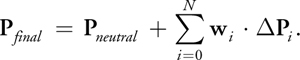
Mathematically, blend shapes are very simple. A blend shape is simply the per-vertex difference between a reference, or neutral, pose and the intended pose. This set of pervertex differences can be thought of as a mesh of vectors. The difference vectors contained in this mesh not only cover the vertex positions, but they also cover other properties such as surface normals, texture coordinates, and tangent vectors. If P is a vertex in the mesh, then the following equation demonstrates how to compute the blend shape vector for the ith pose of P:
|
P i = P i — P neutral · |
Creating the final vertex is as simple as computing a weighted sum of all the blend shapes for the present animation:
3.2.1 Features of DirectX 10
The blend shapes algorithm can take advantage of the following major DirectX 10 features:
- Stream-out. Stream-out allows a vertex shader to operate on a batch of vertices but write them back to a buffer instead of forwarding them down the graphics pipeline to become triangles and eventually pixels. This powerful capability allows an arbitrary number of processing phases for blend shapes.
- HLSL buffer template. This provides access to an unsized data buffer for holding blend shape data.
- VertexID. The VertexID system value provides a convenient reference to the vertex in the mesh that is currently being processed. This allows the shader to fetch additional blend shape data not in the vertex buffer.
3.2.2 Defining the Mesh
Some regions of the mesh are unaffected by the animations driven from the blend shapes. As an optimization, these regions are rendered separately without any of the blend shape shading.
For example, under this approach, we compute the expression on Dawn's face by providing the following to the GPU:
- One neutral mesh. This mesh contains the vertex positions, normals, tangents, and texture UVs.
- Fifty-four expressions (blend shapes). These shapes contain the differences that we need to add to the neutral mesh to reach each new expression. We typically store the positions, normals, and tangents (the binormal vector can be computed in the vertex shader). There is no need to store the attributes that do not change (such as texture coordinates).
We use Maya to create the blend shape data, and we export the final mesh in a custom format made of a sequence of blocks, as shown in Figure 3-2.
)
Figure 3-2 Each Blend Shape Encodes Delta Information Relative to the Original Mesh
If we consider these blocks as DirectX 10 slots, slot 0 would contain the base mesh with interleaved data made of position, normal, tangent, and texture coordinates. Additional slots would be filled with the 54 blend shapes, with each slot containing position difference, normal difference, and tangent difference. This would result in 166 attributes per vertex, if all blend shapes were bound concurrently. Clearly this greatly exceeds the limits of DirectX 10 hardware, but even a small subset such as 4 active blend shapes, exceeds the 16 attributes available. The two methods presented next in this chapter offer solutions to this problem.
3.2.3 The Stream-Out Method
One way to work past the limitations on the number of attributes in DirectX 10 is to operate on the mesh in an iterative fashion. By combining a subset of the presently active blend shapes in each pass, we need only a small number of attributes in each pass. Each pass can select between one and four of the active blend shapes and place them into slots. These blend shapes are added to either the results of the last blending pass, or for the first pass, they are added to the base mesh. While this method does require multiple passes over the data, in practice, the required number of passes is likely to be quite low (seven passes would be enough to apply more than one-half of the total blend shapes available for our Dawn model).
In our case, we could add four blend shapes, as shown in Figure 3-3 and Listing 3-1.
)
Figure 3-3 Only a Subset of the Total Blend Shape Set Is Used at Once
Example 3-1. Vertex Structure Used to Contain the Mesh and Blend Shape Information
struct Face_VSIn
{
  float3 pos : position;
  // Neutral shape from slot 0
  float3 normal : normal;
  float3 tangent : tangent;
  float2 tc : texcoord0;
  float3 bsP0 : bs_position0; // Blend shape 0 from slot 1
  float3 bsN0 : bs_normal0;
  float3 bsT0 : bs_tangent0;
  .
  .
  .
  [Same for blend shapes 1, 2, and 3 bound to slots 2, 3, and 4]
};- The first slot will contain the mesh attributes.
- Four other slots will be added to provide four facial expressions on top of the neutral one. For efficiency reasons, we try to avoid sending null expressions.
The maximum number of blend shapes applied in a single pass depends on how many fit in the 16 available attributes. More blend shapes can fit in a single pass if the data is compressed (for example, packing normalized vectors into 32 bits or using fewer components) or if the data has fewer components (such as no tangent vectors). For simplicity, the examples in this chapter use a maximum of four blend shapes on top of the main mesh.
The shader in Listing 3-2 demonstrates how the input data is processed for a single pass.
To iterate over the data, the algorithm must dump the results out after vertex shading. To facilitate this, the new DirectX 10 stream-out functionality allows the vertices to be written back to a buffer after the execution of the vertex shader, and it allows the geometry to (optionally) not be rendered during this pass. By binding the result of the nth pass as the base mesh for the (n + 1)th pass, the effects of the blend shapes for all passes can be accumulated. To maximize the efficiency of the operation, the algorithm needs two buffers to hold the stream-out results. This way, the shader can ping-pong between them, using the first buffer for output and the second buffer for input on oddnumbered passes, and vice versa on even-numbered passes. Before each of these passes, a constant buffer containing the weights (weightBS) needs to be updated with the proper weightings for the next set of blend shapes. Once all the blend shapes have been accumulated in this manner, this output vertex buffer is ready to be used as the input vertex buffer to render the scene as it normally would be done. Figure 3-4 illustrates the process.
)
Figure 3-4 Stream Output Enables Multipass Blend Shape Computations
Example 3-2. The Basic Blend Shapes Computation
Face_VSStreamOut VSFace(Face_VSIn input)
{
  Face_VSStreamOut output;
  output.pos = input.pos + (weightBS[0].xxx * input.bsP0) +
               (weightBS[1].xxx * input.bsP1) + (weightBS[2].xxx * input.bsP2) +
               (weightBS[3].xxx * input.bsP3);
output.normal = [. . . similar equations as for pos . . .]
output.tangent = [. . . similar equations as for pos . . .]
output.tc = input.tc;
return output;
}
Note that we never perform any CPU readback of our data: everything is kept within vertex/stream buffers. Therefore, you have to tell this buffer that it is a receiver for streamed data (D3D10_BIND_STREAM_OUTPUT) and a source for the Input Assembler (D3D10_BIND_VERTEX_BUFFER).
3.2.4 The Buffer-Template Method
An alternative to using the CPU to drive the iteration over the active blend shapes, as occurs in the stream-out method, is for the GPU to perform the iterations. DirectX 10 enables this by providing flow control in the vertex shader for managing the iterations along with the ability to bind a buffer as a shader resource view to provide access to the data. This buffer is available through a template in HLSL, which can be read by using the Load() method:
Buffer myBuffer;
...
float3 weight = myBuffer.Load(x);
In the application, this shader resource view is created from any buffer that was created with the D3D10_BIND_SHADER_RESOURCE flag. Once the resource has been created, it is bound to the effect variable like this:
ID3D10EffectShaderResourceVariable *v;
. . .
v->SetResource(myRV);
Using a shader resource to hold the blend shape data, this method breaks the input data set into two types. The base mesh is read through the input assembler, while the blend shape data are all loaded explicitly in the shader from the resource view of the buffer. Utilizing loads from the buffer means that an effectively unlimited amount of blend shape data can be read in with a single invocation of the vertex shader.
In addition to the nearly unlimited loads, a buffer provides other advantages over alternative solutions. Textures are restricted to 8,096 elements in a single direction, and while 2D and 3D textures extend the total addressable size beyond the size of video memory, the extra arithmetic for computing row and column offsets is an undesirable complexity. On the other hand, buffers support more than sixteen million elements in a simple 1D package.
With this method, we use this type of buffer to store all the blend shapes in one single big buffer. As mentioned previously, creation of this buffer requires a special binding, D3D10_BIND_SHADER_RESOURCE, so we can create a 1D (D3D10_SRV_DIMENSION_BUFFER) shader resource view. Additionally, because blend shapes are not modified at all at runtime, declaring the buffer as immutable (D3D10_USAGE_IMMUTABLE) ensures that it is allocated in the most optimal way. See Listing 3-3.
To address the blend shape components, the shader can utilize the SV_VertexID semantic introduced in DirectX 10. This semantic provides the element number currently being processed. By combining this element number with the stride and pitch of the blend shape elements, the shader can easily compute the proper offset for the Load() function to retrieve the necessary blend shape elements.
Obviously, the shader must be restricted to process only those blend shapes currently in use. This is done by using an additional pair of buffers that store the indices and weights of the active blend shapes. The number of meaningful entries in these buffers is provided by the variable numBS. The index buffer, weight buffer, and the numBS variable are all updated every frame. To optimize this usage pattern, the buffers are declared with D3D10_USAGE_DYNAMIC (telling DirectX that it will be updated frequently) and D3D10_CPU_ACCESS_WRITE (telling DirectX that it will be updated directly from the CPU). Listing 3-4 shows how the blend shapes are accumulated in this method. Figure 3-5 illustrates the process.
)
Figure 3-5 Using Loops Reduces the Number of API Calls to One
Example 3-3. Data Declaration and Resources Creation
D3D10_BUFFER_DESC bufferDescMesh = {sizeBytes, D3D10_USAGE_IMMUTABLE,
                                    D3D10_BIND_SHADER_RESOURCE, 0, 0};
D3D10_SUBRESOURCE_DATA data;
data.SysMemPitch = 0;
data.SysMemSlicePitch = 0;
data.pSysMem = pVtxBufferData;
hr = pd3dDevice->CreateBuffer(&bufferDescMesh, &data, &pVtxResource);
D3D10_SHADER_RESOURCE_VIEW_DESC SRVDesc;
ZeroMemory(&SRVDesc, sizeof(SRVDesc));
SRVDesc.Format = DXGI_FORMAT_R32G32B32_FLOAT;
SRVDesc.ViewDimension = D3D10_SRV_DIMENSION_BUFFER;
SRVDesc.Buffer.ElementOffset = 0;
SRVDesc.Buffer.ElementWidth =
    numBlendShapes * vertexCount * (vtxBufferStrideBytes / (3 * sizeof(float)));
hr = pd3dDevice->CreateShaderResourceView(pVertexResource, &SRVDesc,
                                          &pVertexView);
To get to the final vertex position, the vertex shader simply
- Loops over these two arrays of indices and weights
- Retrieves the corresponding vertex attributes in the blend shape pointed out by the index
- And finally adds these contributions to the final vertex
If you compare this approach with the previous method, you see that now the whole construction of the final shape is performed in one single draw call: we don't need to drive the iterations by sending additional draw calls. Instead, we stay in the vertex shader and loop in it depending on how many blend shapes need to be processed.
Example 3-4. A More Flexible Way of Computing Blend Shapes
for (int i = 0; i < numBS; i++)
{
  uint offset = bsPitch * bsOffsets.Load(i);
  float weight = bsWeights.Load(i);
  dp = bsVertices.Load(offset + 3 * vertexID + 0);
  dn = bsVertices.Load(offset + 3 * vertexID + 1);
  dt = bsVertices.Load(offset + 3 * vertexID + 2);
  pos += dp * weight;
  normal += dn * weight;
  tangent += dt * weight;
}
Listing 3-5 shows the final sample code for this vertex shader.
Although this method is more efficient, you need to be aware of a limitation in DirectX 10 when using buffers to read vertex data:
Example 3-5. Initialization Code Surrounding the Loop Featured in Listing 3-4
Head_VSOut VSFaceBufferTemplate(Head_VSIn input, uint vertexID : SV_VertexID)
{
  Head_VSOut output;
  float3 pos = input.pos;
  float3 normal = input.normal;
  float3 tangent = input.tangent;
  float3 dp, dn, dt;
  for (int i = 0; i < numBS; i++)
  {
    uint offset = bsPitch * bsOffsets.Load(i);
    float weight = bsWeights.Load(i);
    dp = bsVertices.Load(offset + 3 * vertexID + 0);
    dn = bsVertices.Load(offset + 3 * vertexID + 1);
    dt = bsVertices.Load(offset + 3 * vertexID + 2);
    pos += dp * weight;
    normal += dn * weight;
    tangent += dt * weight;
  }
}- In the shader code, it is impossible to use a user-defined type for data (for vertex attributes) in the Buffer<> template. Only basic types such as float, float3, and so on can be used.
- In the application code, when we create a shader resource view to bind to the buffer, we face the same problem: only the types from the DXGI_FORMAT enum are available. There is no way to specify a complex input layout made of different formats in a resource view.
This issue is not a problem at all in our case because our blend shapes are made of three float3 attributes (position, normal, and tangent). So we can simply declare a buffer of float3 and step into it three by three. However, there is a problem if you want to read a set of vertex attributes made of different widths, say, float2 for texture coordinates, float4 for color, and so on.
The easiest workaround is to pad the shorter data. For example a float2 texture coordinate will have to be float4 in memory, and the shader will use only the first two components. But this trick requires us to prepare data with some "holes" in it, which is not very elegant and takes more memory. A more complicated workaround would be to read a set of float4 values and to reconstruct the vertex attributes by ourselves in the shader. As an example, we may be able to use the third components of position, normal, and tangent to reconstruct another three-component vector. We didn't test anything related to this issue, and so we leave it to the reader to find some compression solutions.
3.3 Running the Sample
The sample available with this book shows how to combine 54 facial expressions on the face of the Dawn character. The demo starts with the animation turned on. This animation is simply reading a set of curves to animate a few weights.
We arbitrarily grouped these expressions two by two in 26 groups: you can play with two sliders to vary the 54 expression intensities. Note that if the animation is on, you may not be able to use the sliders that are being animated. However, check out the ones you can change (try Group 6, for example) at the same time the animation is running: this is a good example of how you can combine complex expressions. There is a combo box that allows you to switch between the two modes. Finally, some sliders are available so you can change the lighting of Dawn's skin.
3.4 Performance
Performance varies depending on how many expressions we use. The first technique, using stream-out buffer, is slower than the second, using buffer templates and shader resource views. The main reason for this slowdown is that the first is streaming out the data as many times as needed: the more expressions we have, the more times we will loop through the stream buffer, back on the CPU. In the second implementation, everything is performed inside the vertex shader and no intermediate data needs to be streamed out from the GPU pipeline.
The gap in performance between the methods increases as we add more blend shapes, as you can see in Figure 3-6. With 6 blend shapes, the second method is already 1.34 times faster than the first one. When we reach 50 blend shapes, the second method is 2.4 times faster.
)
Figure 3-6 Frame Rate per Second for Various Numbers of Blend Shapes
Although the second implementation may appear to be the better choice, the first one is still an interesting technique as long as you use a reasonable number of blend shapes.
In some situations, it could be useful to save the final result of a blend shape combination. For example, blend shapes could be used to customize a character and then you could save the result for the rest of the game, so you don't need to recompute it. The stream-out mechanism would be necessary for this operation, but we leave it to the reader to figure out how easy it is to integrate one technique versus the other in a particular engine.
3.5 References
Beeson, Curtis. 2004. "Animation in the 'Dawn' Demo." In GPU Gems, edited by Randima Fernando, pp. 63–72. Addison-Wesley.
Hagland, Torgeir. 2000. "A Fast and Simple Skinning Technique." In Game Programming Gems, edited by Mark DeLoura. Charles River Media.
- Contributors
- Foreword
- Part I: Geometry
-
- Chapter 1. Generating Complex Procedural Terrains Using the GPU
- Chapter 2. Animated Crowd Rendering
- Chapter 3. DirectX 10 Blend Shapes: Breaking the Limits
- Chapter 4. Next-Generation SpeedTree Rendering
- Chapter 5. Generic Adaptive Mesh Refinement
- Chapter 6. GPU-Generated Procedural Wind Animations for Trees
- Chapter 7. Point-Based Visualization of Metaballs on a GPU
- Part II: Light and Shadows
-
- Chapter 8. Summed-Area Variance Shadow Maps
- Chapter 9. Interactive Cinematic Relighting with Global Illumination
- Chapter 10. Parallel-Split Shadow Maps on Programmable GPUs
- Chapter 11. Efficient and Robust Shadow Volumes Using Hierarchical Occlusion Culling and Geometry Shaders
- Chapter 12. High-Quality Ambient Occlusion
- Chapter 13. Volumetric Light Scattering as a Post-Process
- Part III: Rendering
-
- Chapter 14. Advanced Techniques for Realistic Real-Time Skin Rendering
- Chapter 15. Playable Universal Capture
- Chapter 16. Vegetation Procedural Animation and Shading in Crysis
- Chapter 17. Robust Multiple Specular Reflections and Refractions
- Chapter 18. Relaxed Cone Stepping for Relief Mapping
- Chapter 19. Deferred Shading in Tabula Rasa
- Chapter 20. GPU-Based Importance Sampling
- Part IV: Image Effects
-
- Chapter 21. True Impostors
- Chapter 22. Baking Normal Maps on the GPU
- Chapter 23. High-Speed, Off-Screen Particles
- Chapter 24. The Importance of Being Linear
- Chapter 25. Rendering Vector Art on the GPU
- Chapter 26. Object Detection by Color: Using the GPU for Real-Time Video Image Processing
- Chapter 27. Motion Blur as a Post-Processing Effect
- Chapter 28. Practical Post-Process Depth of Field
- Part V: Physics Simulation
-
- Chapter 29. Real-Time Rigid Body Simulation on GPUs
- Chapter 30. Real-Time Simulation and Rendering of 3D Fluids
- Chapter 31. Fast N-Body Simulation with CUDA
- Chapter 32. Broad-Phase Collision Detection with CUDA
- Chapter 33. LCP Algorithms for Collision Detection Using CUDA
- Chapter 34. Signed Distance Fields Using Single-Pass GPU Scan Conversion of Tetrahedra
- Chapter 35. Fast Virus Signature Matching on the GPU
- Part VI: GPU Computing
-
- Chapter 36. AES Encryption and Decryption on the GPU
- Chapter 37. Efficient Random Number Generation and Application Using CUDA
- Chapter 38. Imaging Earth's Subsurface Using CUDA
- Chapter 39. Parallel Prefix Sum (Scan) with CUDA
- Chapter 40. Incremental Computation of the Gaussian
- Chapter 41. Using the Geometry Shader for Compact and Variable-Length GPU Feedback
- Preface