
In the first post on ray-traced caustic effects, we introduced mesh caustics and its usages in Unreal Engine 4. In this second post, we describe water caustics. The beta version of the source code and sample assets have been released in the UE4 NVRTX_Caustics repository. For more information, see the Release Information section at the end of this post.
Water caustics
Water caustics are a common effect in scenes containing water surfaces. In most rasterization-based game engines, it was perfunctorily made of scrolling textures due to the lack of fast ray-tracing support. At GDC 2019, Holger Gruen presented a method based on caustics mapping to implement surface and volumetric caustics on DXR, which made real-time, ray-traced water caustics feasible for games. This became the basics of our approach.
Compared to a regular mesh that casts caustic, a water surface is highly dynamic and interactive. It should be rasterized into an intermediate buffer rather than put into BVH. It often covers a large scene area, which requires an efficient mechanism to handle the large amount of ray-tracing data. Water surfaces only require one-bounce reflection or refraction to generate caustics, which gives much better performance than typical mesh caustics.
To address these special characteristics of water caustics, we continued Gruen’s work and improved it over several aspects: maintaining sharper details in caustic patterns by applying photon difference or procedural meshes; being able to cover vast scene regions through cascaded caustics maps; and providing user controlled bias-variance trade-off. The technique, ray-guided water caustics (RGWC), has been featured in a few games since 2019 and is also available in the NVRTX_Caustics branch.
In this post, we recap Holger’s method and then describe the latest algorithmic improvements, show the usages in UE4, and discuss the rendering performance and quality.
Basic workflow
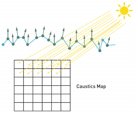
Holger’s caustic method involves mainly two sets of buffers: caustics maps that store rasterized water geometry in light view and caustics buffers that accumulate photon footprints in screen space. The workflow consists of four steps:
- Render water surfaces into caustics maps from the light view, recording the positions and normals of the water surface. (Figure 2, quoted from Holger’s article).
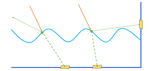
- Generate rays from positions recorded in the caustics maps and trace them along the reflected or refracted directions calculated from the surface normals. After the rays hit the scene, record the information of the hit points.
- Render caustics into the caustics buffer, which is placed in screen space, using the data of the hit points obtained in step 2.
- Perform denoising on the caustics buffer and composite the result with the scene.
For more information about volumetric caustics, see Holger’s article in the book Ray Tracing Gems. Our improvements focus on the surface caustics in step 2 and step 3. In step 2, instead of only outputting the intensity of the ray hit point, we count the number of valid hit points and record more data including position and direction. In step 3, we developed two independent approaches for generating better caustic patterns:
- Photon difference scattering (not photon differentials), which treat each ray hit point as a photon and render it as a decal against the scene depth
- Procedural caustic mesh, which reconstructs the caustic network as a triangular mesh, and then blends it with the scene.
As both approaches have pros and cons, you can switch the two through UI options based on the preference of higher quality or better performance. Besides these overhauls, we also introduced cascaded caustic maps, an analog to cascaded shadow maps, to cover mass water bodies by multi-scale rendering.
Using water caustics in the UE4 editor
Water caustics can be enabled for animated water and interactive water in the UE4 editor with the following steps:
- Enable a light to cast water caustics by checking Cast Water Caustics in the light’s properties.
- For water meshes that need to generate caustics, check Evaluate Ray Tracing Water Caustics in their properties.
- Use a post-process volume to contain the water mesh and configure the parameters under Ray Tracing Water Caustics. The option Caustics Type can be set to either Photon Difference Scattering or Procedural Caustic Mesh. The details for the two types are explained in the following sections.
Photon difference scattering
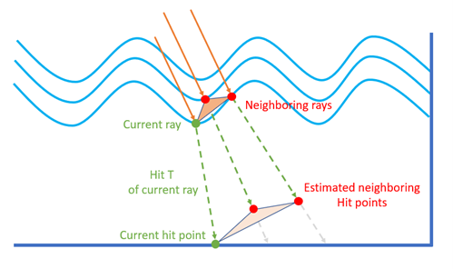
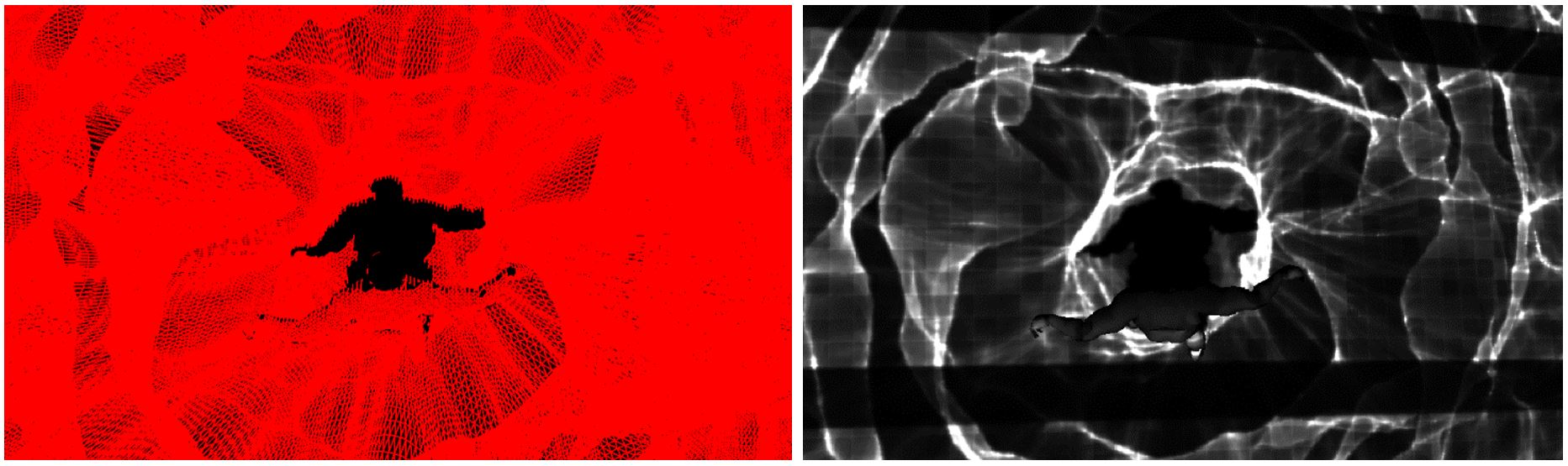
In this approach, you treat ray hit points as photon footprints and render them as decal sprites against scene depth. Figure 3 shows the photon footprints being rendered at a fixed size, which forms correct caustic envelopes but either leaves gaps or overlaps in between footprints. To fill the scene surface with compact quads, you have to find a proper size for each footprint. Fortunately, for water caustics, each ray is cast from one single reflection or refraction. That means that you can easily backtrace to the ray’s origin in the caustics map and access its adjacent rays’ origins and directions. The right size and shape of the footprint are then estimated using these ray data around the hit point (Figure 4). The intensity of the quad sprite is also adjusted by the quad area and the surface normal during the scattering. This technique, like photon differentials, uses finite-difference of nearby rays’ data to compute photon coverage, which can give more accurate results than using local perturbations as in photon differentials.
With PDS, you can obtain the same quality of the original caustics mapping method by much sparser rays, thus greatly improving the ray-tracing performance. The brightness adjustment by footprint coverage ensures correct intensity distribution from all incident angles, while some slope angles may raise artifacts in Gruen’s method. Figure 4 shows the result after applying the technique: the footprints have formed into continuous patterns without utilizing any form of denoising.
On the plus side, this approach can render high-quality water caustics with low cost, and easily extend the supports for many types of light sources, including area light. On the minus side, it is sensitive to the caustics map resolution related to the covering range. Applying a low-resolution caustics map to a large scene area may result in blurry caustic patterns (Figure 5).
Procedural caustic mesh
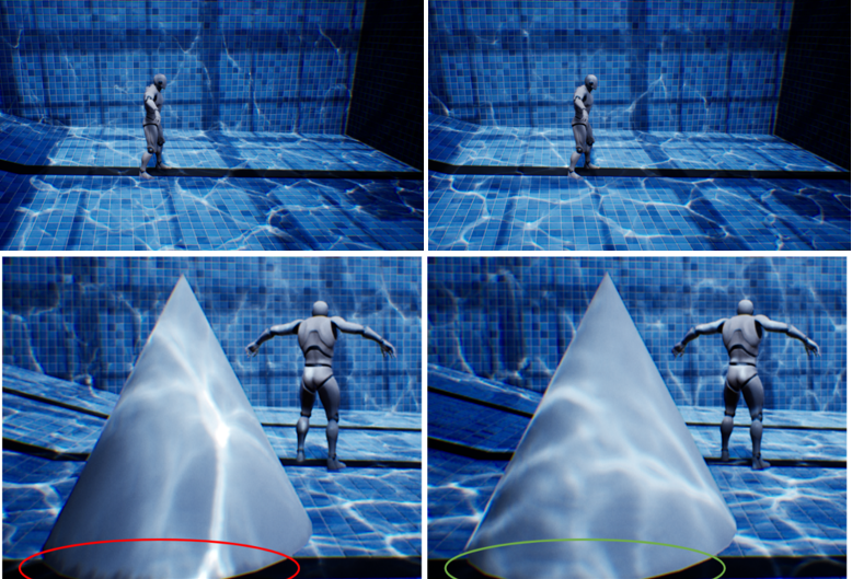
Another approach for generating caustic patterns from ray-tracing results is to convert hit points into an intermediate mesh: each hit point is mapped to a vertex in the mesh whose topology is a triangle list that maps to regular grids on the caustics map. After the ray-tracing pass, a compute shader fetches the hit point data, evaluates the contribution and intensity of each primitive according to its world space area, discards invalid primitives, and generates an index buffer. The mesh is then rendered onto the caustics buffer in a rasterization pass (Figure 6). In practice, you build two procedural caustic meshes for every water object, one for reflection and the other for refraction.
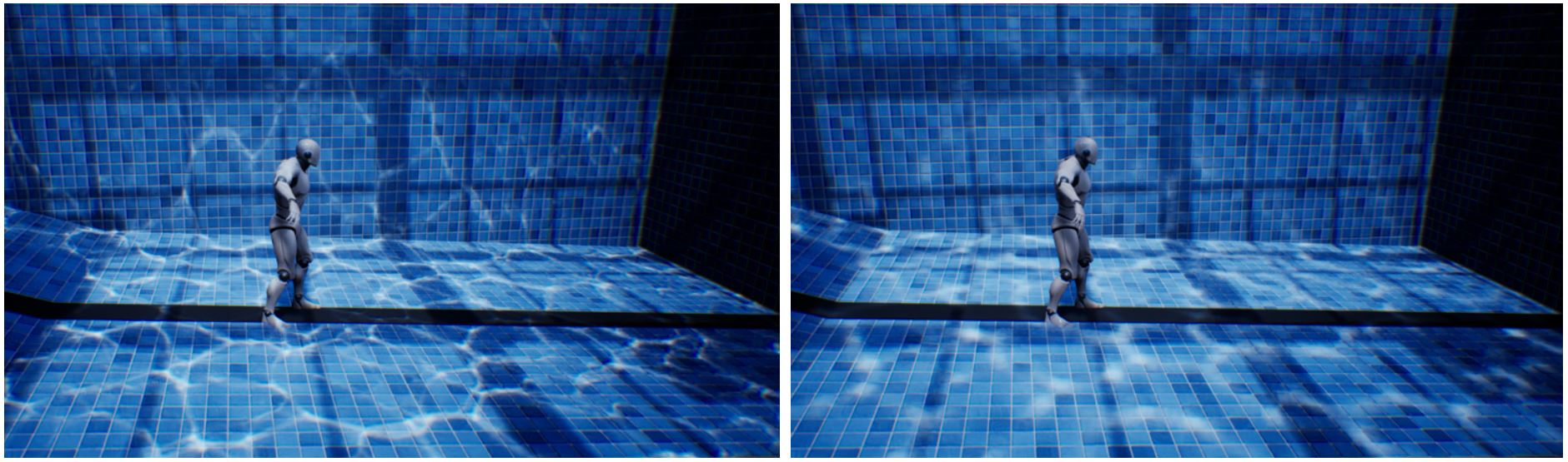
The advantage of this approach is that it always produces sharp caustic patterns even though the caustics map resolution is low (Figure 7). However, it also raises the black-edged artifact at the corners around objects where the mesh triangles span over the culling region. For the best result, you can pick one from PDS and PCM to find the ideal quality-performance balance. In general, PDS is more flexible, well-suited for water areas in a confined space like a swimming pool, while PCM is more efficient when coupling with large water bodies, such as lakes and the ocean.
Cascaded caustic maps
To render caustic effects with large water bodies like ocean surfaces, we implemented the method of cascaded caustic maps, which works in the same way as cascaded shadow maps. Figure 8 shows a configuration of four cascades, where each cascade contains a caustics map at a user-selected resolution. You can use CCM with PDS to mitigate a blurry result when rendering with a limited photon budget but higher details are wanted at near sight, as it allows you to distribute more photons at the innermost cascade to lift the quality and fewer photons at the outskirt cascades to keep the cost down.
In the UE4 editor, you can enable CCM by setting Num Water Caustics Map Cascades greater than 1 in the corresponding light source property. The size of the innermost cascade is decided by the Directional Lighting Range value under the post-process volume’s Ray Tracing Water Caustics group, and the outer cascade sizes are determined by multiplying the value of Water Caustics Map Cascade Scale in the light source property.

Image quality and performance
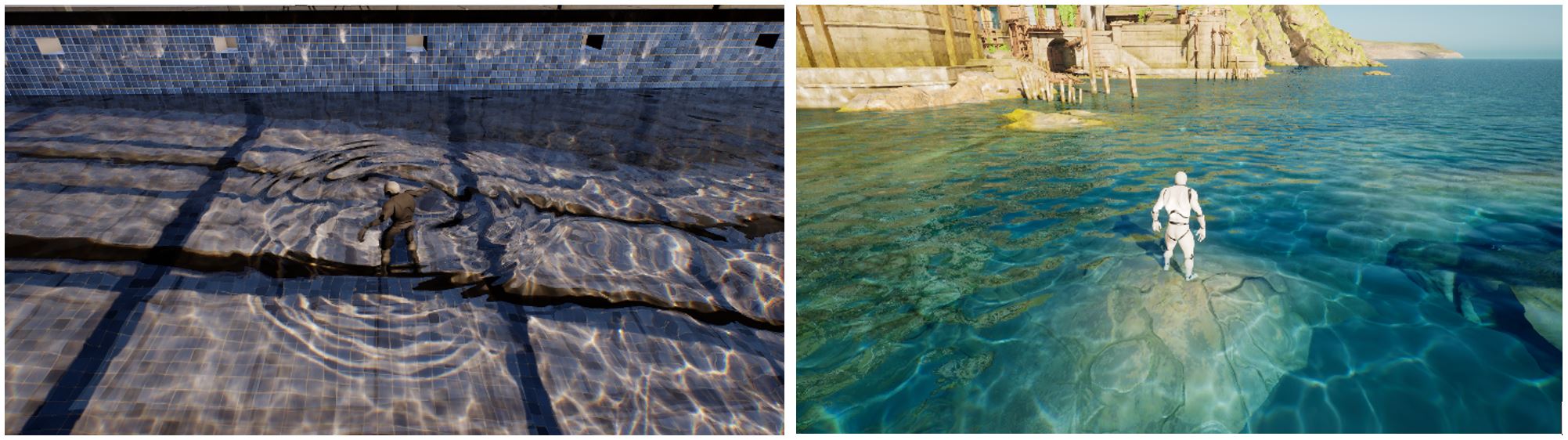
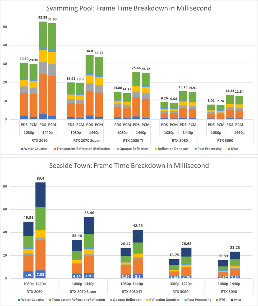
We used two scenes in Figure 9 for performance testing. The swimming pool scene contains one directional light casting caustics, and the size of the caustics map is set to 1024×1024. Almost the entire screen is covered by either refracted (underwater) or reflected (above water) caustics. The seaside town scene has a four cascades setup to cover a large enough area of the sea surface, which adds more computational pressure on the ray-tracing part. Figure 10 shows the performance charts, where the data is collected by UE4 command stat gpu.
You can draw several conclusions from the performance data:
- The top rendering buckets are ray-traced water reflection, refraction and related denoisers, miscellaneous (lights, RTAO, volumetric fog, and so on) and opaque reflection on the surroundings. In all test cases, the water caustics take less than 13% of frame time. In a common use case that only contains one caustic-casting light, you can expect that the cost of water caustics falls into the range 0.5–2ms, according to different NVIDIA RTX GPUs.
- PDS and PCM have roughly the same cost. The choice between the two can be based on the image quality.
- The two main hotspots of water rendering are the ray-tracing process, whose cost is affected only by the size of the caustics map; and photon footprint rendering (PDS) or mesh reconstruction (PCM), whose cost is related to screen resolution.
To balance between the image quality and performance of water caustics, consider the following suggestions:
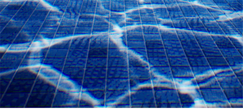
- Try the PDS method first for better looking details, flexibility, and area lighting support if soft caustics are desired. At the highest caustics map resolution, PDS should be good to produce fine-detailed caustic patterns for water surfaces on the scale of a swimming pool without an overly blurred look.
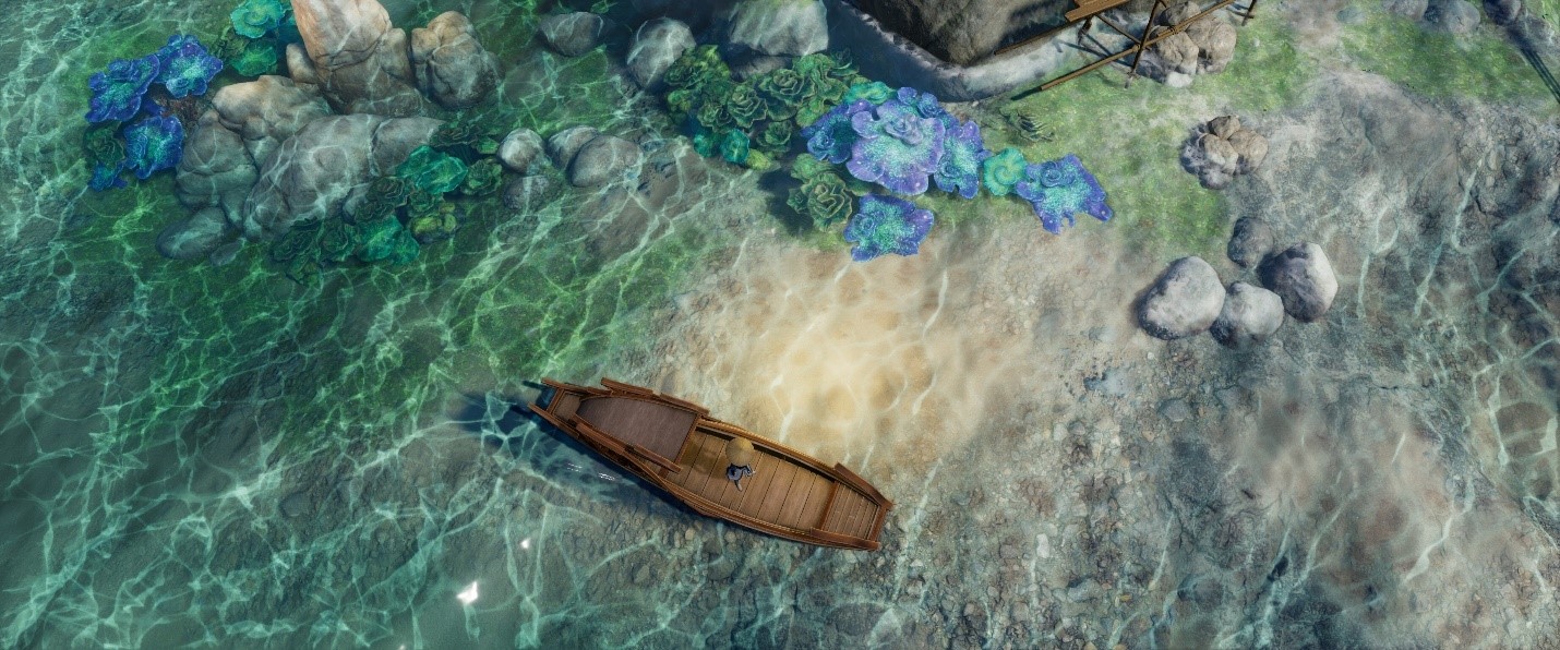
- Use the PCM method if both crisp caustic patterns and large scene coverage are required. For scenes filled with huge water bodies like lakes and seas, PCM can output sharp caustics in most places with low performance overhead (Figure 1).
- Cascaded caustic maps can be combined with PDS to extend the caustic coverage to a vast view distance. This is the best way to handle aerial view over large water bodies.
- For better performance, select a proper resolution for caustics maps through the command-line variables:
RayTracing.WaterCaustics.MapSizeXandr.RayTracing.WaterCaustics.MapSizeY. Because higher resolutions substantially increase the number of photons, do not pick a higher resolution if a lower resolution can give you a similar image quality. - If the performance is preferred over quality, enable the half-resolution option with Caustics Buffer Scale under Ray Tracing Water Caustics group in post-process volume. This speeds up the rendering, which sets the caustics map’s size to a quarter of the current main view. This option can roughly cut off 40–50% rendering time for both PDS and PCM.
Release information
The UE4 integration of caustic effects are available for early access at the UE4 NVRTX_Caustics depository. To obtain the access to the branch, follow the Unreal Engine instructions.
Besides ray-traced caustics, this branch contains a series of new RTX features and improvements over existing techniques, including enhanced hybrid translucency, multi-bounce refraction optimization, and a new SVGF based RTGI denoiser. For more information about the sample assets, see the README file in the repository.
The current integration is based on UE4.25.3. All features and optimizations included in the standard UE4 NVRTX branch, for example, DLSS 2.1, hybrid translucency, ray-tracing debug, and visualization, are also included in the caustics branch. For more information about using these NVRTX features and installation steps, see the NvRTX/UnrealEngine GitHub repo.
