RTX is NVIDIA’s new platform for hybrid rendering, allowing the combination of rasterization and compute-based techniques with hardware-accelerated ray tracing and deep learning. It has already been adopted in a number of games and engines. Based on those experiences, this blog aims to give the reader an insight into how RTX ray tracing is best integrated into real-time applications today. This blog assumes that the reader is familiar with the Microsoft DXR API at a basic level.
For API introduction, refer to the following:
- Introduction to NVIDIA RTX and DirectX Ray Tracing
- DirectX Ray Tracing Tutorial Part I
- DirectX Ray Tracing Tutorial Part II
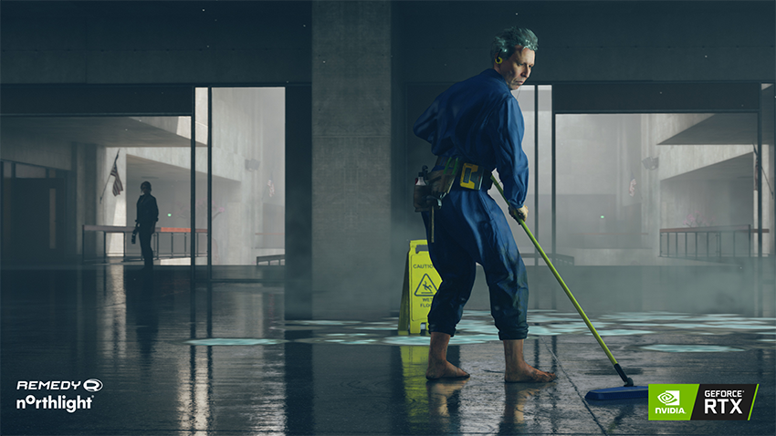
While ray tracing can produce much more realistic imagery than rasterization, it is also computationally intensive. The best approach for real-time applications is hybrid rendering, a combination of ray tracing and rasterization. Figure 1 shows an example of hybrid rendering. Rasterization is used where it is most effective while ray tracing is used where it provides the most visual benefit compared to rasterization. The typical use cases for ray tracing include reflections, diffuse global illumination, shadows, and ambient occlusion while primary visibility is resolved through rasterization as before. Another potential use case for RTX is to implement a more complete path tracer for non-real-time light map baking or for use as a reference in content production and development of less accurate real-time techniques.

In order to trace rays against your content, you must first build ray tracing acceleration structures. Building starts from bottom level acceleration structures. This is fairly trivial for non-deformable meshes since you need to only build the structures once and you don’t need to touch them each frame.
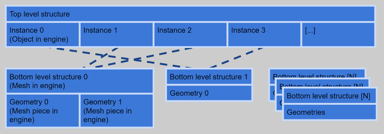
However, you should keep a few things in mind to improve performance and efficiency. You can utilize instancing when several objects share a mesh, allowing you to build only one bottom level structure for those objects and refer to it in several top-level instances. This obviously saves memory and can improve performance too. It’s advisable to build only one bottom level structure for several meshes when possible. Each mesh is then a separate geometry in the same bottom level structure. This can be done when the meshes would have the same top-level transformation.
For example, that can happen when you have a mesh that is split into several pieces with different materials. Note an additional fixed transformation can be given to each mesh in a bottom level structure. Combining several meshes to a single bottom level structure saves memory and increases ray tracing performance. Figure 2 illustrates bottom level structure instancing and merging.
Deformable Meshes
You must consider how to update the bottom level acceleration for structure for deformable meshes most efficiently on each frame. It’s often a good idea to output the vertex data of a deformable object for a given frame to a buffer as triangles and then use that as an input to build a bottom level structure. When tracing rays against a triangle mesh geometry, you can use the fixed function triangle intersection, which offers the best performance. The vertex data can be output to UAVs or with stream out, either as a side effect of some preceding rasterization pass or in a dedicated pass run for all objects requiring it. The most important optimization is to skip the bottom level update altogether if it’s not needed on a given frame. For example, if the skinning matrices of a skinned object have not been modified, the acceleration structure from previous frame can be reused.
Build Flags
At build time, structures can be marked as updatable with the ALLOW_UPDATE flag. This slightly increases both the initial build time and ray tracing cost but allows faster structure updates to be used instead of full rebuilds on subsequent frames. An update operation requires an existing compatible structure as an input. Using updates is a good choice for many deformable objects. Typically, an update instead of a rebuild is a good move when vertices of the mesh have not moved very far away from their positions on previous rebuild.
If an update is done after significant vertex movement, ray tracing performance against the object may become suboptimal. Some objects, such as unbreakable animated characters, have vertices which always sty inside a limited bounding volume. Update can always be used after the initial build in these cases. Additionally, it’s advisable to try to distribute structure rebuilds of different objects to happen on different frames and avoid situation where many rebuilds are piled up to happen on a single frame.
In addition to marking an acceleration structure as updatable, the API offers two preference flags, PREFER_FAST_TRACE and PREFER_FAST_BUILD, used in acceleration structure building. Selecting the optimal flags based on how an object is going to be used can significantly improve overall performance. Table 1 describes flags for typical use cases.
Acceleration structure memory consumption can be reduced with the MINIMIZE_MEMORY flag, but using it is not recommended unless otherwise there would not be a sufficient amount of memory. It can reduce ray tracing and structure build performance. The ALLOW_COMPACTION flag is orthogonal to the MINIMIZE_MEMORY flag. With it, a separate compaction operation is required after the structure build operation to reduce memory footprint, but this can be done without sacrificing ray tracing performance. It typically makes most sense for non-deformable meshes for which acceleration structures are never rebuilt.
| # | Preference | Updatable | Properties | Use case |
| 1 | Fast trace | no | Fastest possible trace. | Default choice for non-deformable geometry. |
| 2 | Fast trace | yes | Slower trace than #1 but allows fast updates. | Hero character, high detail deformable objects that are expected to be hit by a significant number of rays. |
| 3 | Fast build | yes | Slower build than #4 but allows very fast updates. | Lower detail deformable objects, unlikely to be hit by too many rays. |
| 4 | Fast build | no | Fastest possible build. | Fully dynamic geometry with potentially changing primitive count or wild deformation like particles and destructibles, that require per-frame rebuild instead of update. |
Resource Barriers
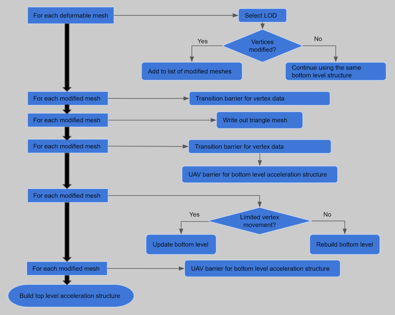
UAV barriers need to be inserted for the buffer used to store acceleration structure data before and after an update or rebuild operation to ensure that the structure is not accessed by DispatchRays() calls while being modified. However, it’s advisable to batch the barriers for all touched structures, then do all the acceleration structure build calls without any barriers between sequential calls. This allows maximum parallelism while executing the build calls. Figure 3 illustrates good resource barrier usage for bottom acceleration structure updates on each frame.
Recording a command list for acceleration structure builds and updates in a worker thread can be a good idea. However, if you use multiple worker threads to record multiple command lists, you should ensure each thread does a considerable number of calls. Many small command lists with only a few calls in each may result in non-optimal build performance.
Memory Management
Storage requirements for bottom level acceleration structures can vary substantially. They can be several megabytes large or consume only a few kilobytes. It’s a good idea to store at least the smallest structures (<64 kb) to larger shared buffer resources to reduce effective memory consumption and avoid fragmentation. It can also increase ray tracing performance. Placed resources in manually created resource heaps can also be used for this. The overall memory consumption of the ray tracing acceleration structures for a game level can be fairly large–up to hundreds of megabytes. This makes it a good idea to do the device resource creation in background threads to keep the game responsive and frame rate smooth during level loading and streaming.
Top Level Structure
The top-level acceleration structure can be marked as updatable like the bottom level structures. When the instances included in the structure stay the same, an update instead of a rebuild can be made. However,the most reliable solution in many cases may be not enabling updates. By always rebuilding the top-level structure, you get optimal ray tracing performance regardless of how objects move in the scene. Typically the cost of building the top-level structure is not high.
As objects may have several geometry LODs, it’s not always obvious which should be used in ray tracing effects by including it in the top-level structure. Using lower detail LODs makes ray tracing slightly faster, but usually selecting the same LOD as used for rasterizing primary visibility ensures correct rendering result. When the LODs used for ray tracing and rasterization do not match, incorrect self-shadows and self-reflections may occur.
Geometries can be marked to be opaque either in bottom level structures with the GEOMETRY_FLAG_OPAQUE or in top level instances with INSTANCE_FLAG_FORCE_OPAQUE. The latter forces all geometries in an instance to be opaque regardless of flags used for individual geometries. Marking geometry as opaque should be done whenever possible as it can significantly improve ray tracing performance by preventing the invocation of any-hit shaders. Note that even if the hit group associated with a geometry lacks an any-hit shader, a geometry not marked as opaque will incur additional overhead during acceleration structure traversal.
Input binding for ray tracing shaders happens through two different mechanisms. You can use the global root table that affects all ray tracing shader stages and bind resources like you would for a compute shader. Additionally, you can define a local root table to bind different resources for each geometry instance and for each ray type. Resource binding through the local root table happens by writing the bindings to the shader table records used in DispatchRays() calls.
The shader table is effectively equivalent to an array of root tables, with data layout specified by the local root signature. For optimal performance, you should use the global root table when possible. However, this often requires use of resource indexing. When this is not possible, local root tables can ease the porting of existing vertex and pixel shader code for ray tracing. Often, you can bind resources for miss shaders and ray generation shaders just through the global root table and not define a local root table at all for them.
Input Binding for Hit Groups
Since hit groups need information about the geometry that was hit – its vertex data and material properties – you typically need a local root table for them. To avoid passing data through the local root table, you may also use the instance id field in the top-level instance descriptor and utilize the instance index, which are implicitly available in the hit group shaders. Remember, though, that these values are shared between all geometries in the instance when the bottom level structure contains more than one geometry. To have unique data for each geometry, a local root table must be used.
Furthermore, utilizing root constants and root descriptors (SRV/UAV/CBV to a buffer) instead of descriptor tables in the local root table may improve performance. Just remember that root descriptors do not support implicit format conversions and checks for out-of-bound access. You don’t necessarily need to use descriptor tables in the local root table at all. You can, for example, have the material textures for the rendered scene in an unbounded array of textures bound through the global root table, and store material index as a root constant in the local root table for selecting the right textures from the array.
StructuredBuffers can be a good way to access vertex data and allow the compiler to best optimize the loading of the data. If you use ByteAddressBuffers, remember to utilize Load4(), Load3(), and Load2() when possible for optimal performance.
Shader Reflection and Automatic Register Assignment
Ray tracing shaders compile as shader libraries instead of individual shader stages. So using shader reflection to resolve required input bindings is slightly different. A natural way to avoid the hassle related to reflection and automatic register assignment is to manually assign registers in HLSL and not rely on shader reflection at all. However, sometimes you may still want to use automatic assignment, perhaps because there is existing code that relies on it.
Conveniently utilizing automatic registers for input bindings may require manual selection of exported library functions. By default, automatic register assignment is not used for libraries. You can enable it with compiler option “/auto-binding-space” and specify a register space used for inputs without manual register assignment. It is important to note that the automatic assignment then happens simultaneously for inputs of all exported functions in the compiled library. In other words, automatic assignment prevents register conflicts between the functions.
It is also important to note that by default all functions are exported. In case all functions are not intended to be used as shader entry points or called from other libraries, manually limiting the exports can prove useful. This may limit the exposed input bindings and reduce the size of the produced code blob. To manually select the exports, you can simply use compiler option “/exports”. Alternatively, you can define functions with static keyword in HLSL to exclude them from library exports.
If you want to use automatic register assignment with ray tracing shaders, one possible way to do it is to compile all shader entry points used in one pipeline state as a single library, limit exports to only the entry functions, and enable automatic register assignment. You can then merge input bindings from all functions seen in the library reflection. When this is done, most bindings can usually be made through the global root table without register conflicts, leaving only some special bindings, perhaps with manual register assignment, to be done through the local root tables.
Pipeline States
For optimal performance, set the smallest possible values for maximum payload size, maximum attribute size, and maximum trace recursion depth in ray tracing pipeline states. Consider using separate pipeline states for different ray tracing-based effects instead of an über pipeline state that contains all possible shaders. This allows setting the maximum limits in the pipeline more accurately for each shader. Pipeline state creation can be expensive. Ensure that you don’t create duplicate states. If state creation happens during game play, consider doing it on background threads.
Parallel shader compilation
A single ray tracing pipeline state may contain lots of shaders. When the shaders are compiled from source code to DXIL libraries, they remain in hardware agnostic format. Creating the ray tracing pipeline state object involves compiling the hardware agnostic code to native format. This work can be distributed to multiple threads by creating collections. Collections are state objects with type D3D12_STATE_OBJECT_TYPE_COLLECTION. Each collection can contain one or more of the shaders used in the final pipeline state object. The created collections become inputs to the pipeline state creation call, which becomes cheaper as the shader code is already compiled to native format.
To allow compilation of shader code to native format during collection creation, the collections must define most of the state that would be defined in the final pipeline state as well. D3D12_RAYTRACING_SHADER_CONFIG must be defined. All shaders require root signatures fully defined with D3D12_GLOBAL_ROOT_SIGNATURE and D3D12_LOCAL_ROOT_SIGNATURE subobjects. Additionally, D3D12_HIT_GROUP_DESC must be defined for intersection, any-hit, and closest-hit shaders. Note that the D3D12_RAYTRACING_SHADER_CONFIG subobjects in all collections and in the pipeline state itself in a pipeline state creation call must match. D3D12_RAYTRACING_PIPELINE_CONFIG does not need to be defined in collections.
Shaders
Whenever possible, do not define a custom intersection shader. Instead, rely on the fixed function intersection test against triangle meshes which provides optimal performance.
Also, define an any-hit shader only when needed. When you do, try to keep it as simple as possible. An any-hit shader is typically required for non-opaque objects to perform alpha testing or transparency. Any-hit shaders can be executed multiple times in a TraceRay(). Everything that needs to be performed only for the closest hit should be implemented in the closest-hit shader, which is executed once at most. As for pipeline states, try to minimize the size of the payload struct passed to hit and miss shaders.
Pay close attention to dependent memory accesses in hit shaders. When reading index and vertex data required for sampling textures and reading material properties, it is easy to create a chain of dependent reads. Shader compiler may not be able to hide the latency of those dependent operations and shortening the chain is a potentially good way to speed up the shaders. Having index and vertex buffers bound as root SRVs may help here too.
TraceRay()
The TraceRay() function is special. It passes control to RTX for invoking hit and miss shaders as needed. Don’t call it carelessly. Carefully test the effects of loop unrolling and branch flattening when there is a TraceRay() call inside. Try to minimize live variables across TraceRay() calls. When a variable is evaluated before TraceRay() and used after, extra work is required for maintaining it during the call.
Use RAY_FLAG_ACCEPT_FIRST_HIT_AND_END_SEARCH in TraceRay() calls when possible. It can significantly improve performance. Usually this can be done with shadow and ambient occlusion rays, which only test whether anything is hit and don’t have to resolve the correct closest hit. Use RAY_FLAG_CULL_BACK_FACING_TRIANGLES only if you need it for correct rendering, eg. if you are handling transparent objects with any-hit-shader and don’t want to process back faces. In ray tracing, back face culling is not an optimization like in rasterization. When it’s correct, RAY_FLAG_FORCE_OPAQUE can be used to treat all geometries as opaque and improve performance in case the opaque properties have not been set in the acceleration structure.
Alpha Testing
While setting the opaque flag in the acceleration structure and not using any-hit shaders is typically the best way to handle opaque surfaces, there is not always an obvious best way to handle non opaque surfaces. However, alpha testing can be done with a fairly straightforward any-hit shader. Note that the dependent memory access issue typical to all hit shaders can be especially pronounced in the alpha test shader as it is so trivial, and the compiler doesn’t have many opportunities for latency hiding.
Transparency
Two fundamental approaches exist for transparency. The lightweight way is to handle the transparent surfaces along the ray in an any-hit shader. The execution order of any-hit shaders for hits along the ray is undefined. Hence, the application must resolve the blend order correctly (or maybe approximately correctly). Remember, though, that the invocations still execute sequentially. Each any-hit invocation sees complete modifications made to the payload data by previous invocations. The closest-hit shader sees complete modifications from all any-hit invocations along the ray.
To prevent processing hits from behind opaque surfaces, you may first cast a ray to probe the distance to the closest opaque surface and then cast another ray that processes the transparent surfaces closer than the opaque surface. If needed, you can utilize the top-level instance cull masks to trace only against selected kind of objects. When tracing primary rays, the opaque depth can potentially be acquired from the rasterized depth buffer. For ideas about how to do the blending in an any-hit shader, for example refer to Weighted, Blended Order-Independent Transparency at https://developer.nvidia.com/content/transparency-or-translucency-rendering.
The rigorous way to handle transparent surfaces is to terminate the ray on closest transparent surface and continue with a new TraceRay() call. The new TraceRay() call can be made recursively from the closest-hit shader or as an additional ray from the ray generation shader. Using multiple rays is more expensive but produces correct blend order and makes it possible to continue the ray to different directions as well, such as correct refraction and reflection directions. Other kinds of recursive rays, like shadow rays, are also possible. Specifically, in shadow rays, treating transparent surfaces like alpha tested surfaces may work reasonably too.
You can also combine the lightweight and rigorous methods by processing a limited number of layers with better quality before continuing with a light approach. Whichever approach is used, it is often advisable to try to match shading and blending of transparent surfaces in ray tracing to rasterization passes as closely as reasonable.
Converting Rasterization Code to Ray Tracing
Sometimes you may want to convert existing shader code used in geometry rasterization to be used in ray tracing against the same geometry. Typically, it means that you create hit groups (intersection, any-hit, and closest-hit shaders) that match unique vertex and pixel shader combinations. Most code can and should be replicated in the closest-hit shader. The hit groups are then used in the ray tracing pipeline state building. The right hit group for each geometry instance is assigned in the shader table along with the unique input bindings for the instance.
In most cases, you get the best performance by avoiding custom intersection shaders completely and handling geometries as non-deformable triangle meshes in ray tracing. For deformable geometries or ones that utilize geometry shaders or tessellation in rasterization, that means additional passes to produce the vertex data. It’s often worth it.
Texture LOD Selection
Pixel shaders use automatic texture LOD selection based on texture coordinate screen space derivatives. But screen space derivatives are not available in hit shaders; manual LOD selection is required instead. Simply using LOD zero is a reasonable solution that works well enough in many cases, in particular if combined with denoising or post processing antialiasing techniques. In case you need something more accurate, the Texture Level-of-Detail Strategies for Real-Time Ray Tracing article in Ray Tracing Gems book available in 2019 offers a good example. A public prerelease version of the article can be found at the NVIDIA Developer site.
Register Consumption
Sometimes, if the shading work intended to be done in hit or miss shaders consumes a lot of registers, it may cause the ray tracing work to be executed with limited occupancy. Ideally, reduce the register consumption by shader refactoring and optimization. Minimizing number of live variables across TraceRay() calls may also help.
Denoising
For stable and smooth results, many ray traced effects require a large number of samples, each potentially with several rays traced in randomized directions. Tracing a sufficient number of rays can be expensive, especially if the effect requires complex shading work in hit shaders. High numbers of rays can be replaced by use of denoising. Denoising is a separate pass performed on the results of ray tracing before combining with other rendering passes. Denoising may work spatially, using data from a pixel’s neighborhood on the current frame. It can also work temporally, using data from pixel history on previous frames, or it can be a combination of both. NVIDIA has created denoisers for different ray traced effects. Some of these denoisers are now available as GameWorks Ray Tracing Denoiser libraries. You can join the early access program for these libraries at https://developer.nvidia.com/gameworks-ray-tracing.
For a more technical description of the denoisers we recommend the following presentation:
http://on-demand.gputechconf.com/siggraph/2018/video/sig1847-edward-liu-ray-tracing-denoisers.html.
Best Practices in a Nutshell
Following is a list of best practices:
- When possible, use triangle meshes instead of AABBs with custom intersection shaders.
- When possible, share bottom level structures for several top-level instances.
- When possible, merge several meshes to a single bottom level structure.
- When possible, skip updating of acceleration structures for deformable meshes.
- When possible, use acceleration structure update instead of rebuild.
- Avoid piling up lots of structure rebuilds to happen on a single frame. Distribute over multiple frames instead.
- Select the optimal build flags depending on mesh usage.
- Mark opaque geometries with the opaque flags either in bottom level structures or in top level instances.
- Do not use the MINIMIZE_MEMORY build flag unless running out of memory.
- Consider using compaction for acceleration structures that are never or rarely rebuilt or updated.
- Batch resource barriers when updating or rebuilding acceleration structures.
- When doing lots of acceleration structure build calls, consider using one or more worker threads for command list recording.
- Store small bottom level structures in larger, shared resources.
- Minimize maximum payload size, maximum attribute size, and maximum trace recursion depth in pipeline states.
- Consider using collections to distribute shader compilation work to multiple threads.
- When possible, use closest-hit shader instead of any-hit shader.
- Consider any-hit shader for non-opaque surfaces.
- Remember that any-hit shader may be executed for hits behind closest opaque surface.
- In hit shaders, pay attention to dependent memory accesses when reading vertex and material data.
- Consider using StructuredBuffers for accessing vertex data. Prefer Load4(), Load3, and Load2() when using ByteAddressBuffers.
- Consider utilizing root constants and root SRVs in vertex data access.
- When possible, use RAY_FLAG_ACCEPT_FIRST_HIT_AND_END_SEARCH.
- Use RAY_FLAG_CULL_BACK_FACING_TRIANGLES only when needed.
- Using texture LOD zero is a reasonable starting point.