We all know and love EVPN as a control plane for VXLAN tunnels over a layer 3 infrastructure. EVPN enables you to deploy VXLAN tunnels without controllers. Plus, it offers a range of other benefits, such as reduction of data center traffic through ARP suppression, quick convergence during mobility, one routing protocol for both underlay and overlay, and the inherent ability to support multitenancy.
So EVPN for VXLAN for all your layer 2 needs, right? Well, it’s a little more complicated than that. You might also have to communicate between VXLANs and between a VXLAN tunnel and the outside world, so VXLAN routing must also be enabled in the network, which I cover in this post.
VXLAN routing can be performed with one of two architectures:
- Centralized routing performs all the VXLAN routing on one or two centralized routers, which can cause additional east-west traffic in the data center.
- Distributed routing provides the VXLAN routing closest to the hosts on the directly connected leaf switches, which simplifies the traffic flow.
This is where VXLAN routing with EVPN comes in. BGP EVPN is used to communicate the VXLAN layer 3 routing information to the leaves.
Using the distributed architecture, the IETF defines two models to accomplish intersubnet routing with EVPN: asymmetric integrated routing and bridging (IRB) and symmetric IRB. Some vendors offer a symmetric model and others offer an asymmetric model.
At NVIDIA networking, we believe that you control your own network. Both models have value, depending on how your network is set up and who might have built your legacy network systems. We offer both solutions so that you can choose whichever method is right for your network.
Difference between asymmetric and symmetric models
The main difference between the asymmetric IRB model and symmetric IRB model is how and where the routing lookups are done. This results in differences concerning which VNI the packet travels on through the infrastructure. Because of these differences, there are variations in how they must be configured on the switch and how they are deployed in your network.
Asymmetric model
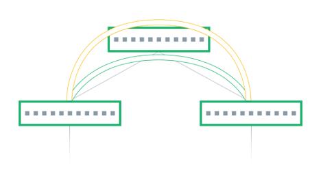
The asymmetric model enables routing and bridging on the VXLAN tunnel ingress, but only bridging on the egress. This results in bidirectional VXLAN traffic traveling on different VNIs in each direction (always the destination VNI) across the routed infrastructure.
Consider the example from earlier. Host A wants to communicate with Host B, which is located on a different VLAN and a different rack, thus reachable through a different VNI.
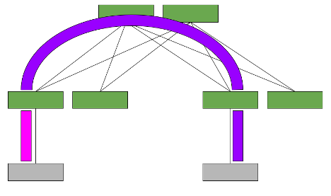
- As Host B is on a different subnet from Host A, Host A sends the frame to its default gateway, which is Leaf01. This is generally an Anycast Gateway.
- Leaf01 recognizes that the destination MAC address is itself, looks up the routing table and routes the packet to the Green VNI while still on Leaf01.
- Leaf01 then tunnels the frame in the Green VNI to Leaf02.
- Leaf02 removes the VXLAN header from the frame, and bridges the frame to Host B.
- Likewise, the return traffic would behave similarly.
- Host B sends a frame to Leaf02.
- Leaf02 recognizes its own destination MAC address and routes the packet to the Orange VNI on Leaf02.
- The packet is tunneled within the Orange VNI to Leaf01.
- Leaf01 removes the VXLAN header from the frame and bridges it to Host A.
With the asymmetric model, all the required source and destination VNIs (for example, orange and green) must be present on each leaf, even if that leaf doesn’t have a host in that VLAN in its rack. This may increase the number of IP/MAC addresses that the leaf must hold, which results in somewhat limited scale. However, in many instances, all VNIs in the network are configured on all leaves anyway to allow VM mobility and to simplify configuration of the whole network. In this case, the asymmetric model is desirable.
While it is not hugely scalable, deployment with the asymmetric model is a simple solution, as no additional VNIs or VLANs must be configured. Additionally, fewer routing hops occur to communicate between VXLANs, which results in lower latency.
Where multitenancy is required, each set of VLANs can also be placed into separate VRFs and routed between the VLANs within a VRF.
Symmetric model
The symmetric model routes and bridges on both the ingress and the egress leaves. This results in bidirectional traffic being able to travel on the same VNI, hence the symmetric name.
However, a new specialty transit VNI is used for all routed VXLAN traffic, called the L3VNI. All traffic that must be routed is routed onto the L3VNI, tunneled across the layer 3 infrastructure, routed off the L3VNI to the appropriate VLAN, and ultimately bridged to the destination.
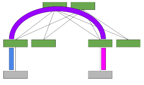
Now consider the scenario with a symmetric model (Figure 2). Host A on VLAN A must communicate with Host B on VLAN B.
- Because the destination is a different subnet from Host A, Host A sends the frame to its default gateway, which is Leaf01.
- Leaf01 recognizes that the destination MAC address is itself and uses the routing table to route the packet to the L3VNI and the next hop Leaf02.
- The VXLAN-encapsulated packet has the egress leaf’s MAC as the destination MAC address and this L3VNI as the VNI.
- Leaf02 performs VXLAN decapsulation and recognizes that the destination MAC address is itself and routes the packet on to the destination VLAN, to reach the destination host.
- The return traffic is routed similarly over the same L3VNI.
With symmetric model, the leaf switches only need to host the VLANs and the corresponding VNIs that are located on its rack, as well as the L3VNI and its associated VLAN. This is because the ingress leaf switch doesn’t need to know the destination VNI.
The ability to host only the local VNIs (plus one extra) helps with scale. However, the configuration is more complex as an extra VXLAN tunnel and VLAN in your network are required. The data plane traffic is also more complex as an extra routing hop occurs and could cause extra latency.
Multitenancy requires one L3VNI per VRF, and all switches participating in that VRF must be configured with the same L3VNI. The L3VNI is used by the egress leaf to identify the VRF in which to route the packet.
Which IRB model is right?
The hardest part of choosing an IRB model is knowing the difference between symmetric and asymmetric methods. Now that you know the difference, you can make an informed decision regarding the best option for your network.
Generally, if you configure all VLANs, subnets, or VNIs on all leaves anyway (for mobility or ease of configuration), the asymmetric model is for you. It’s simpler to configure and doesn’t require extra VNIs to troubleshoot. It may even have slightly less latency.
The asymmetric model also works well if your data center can be broken down into Pods with VLANs and subnets contained in a Pod. Each leaf within the Pod is configured with all VLANs and subnets or VNIs in that local Pod. Other Pods and external networks are reachable through EVPN external routes. EVPN external routing with the asymmetric model is supported in Cumulus Linux 3.6 release, using the L3VNI for external routing only.
If your VLANs, subnets, or VNIs are widely dispersed or provisioned on the fly, choose the symmetric model. The symmetric model supports reachability to external networks with Cumulus Linux 3.5.
NVIDIA believes that you own and control your network, not a proprietary vendor, so we provide both solutions and enable you to choose.
