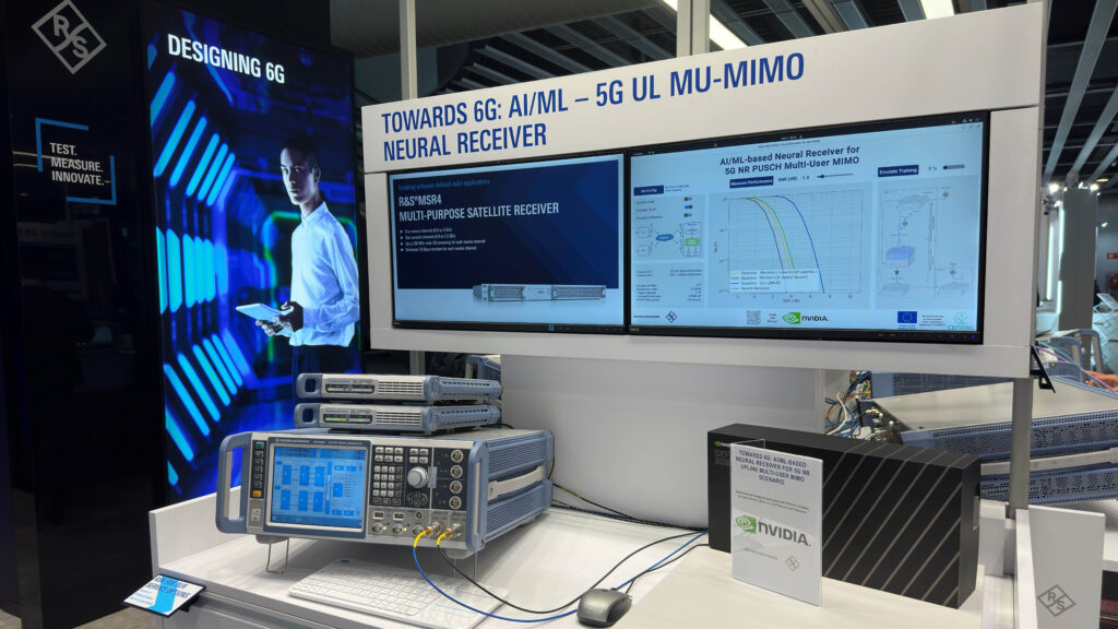
At this year’s Mobile World Congress (MWC), NVIDIA showcased a neural receiver for a 5G New Radio (NR) uplink multi-user MIMO scenario, which could be seen as a blueprint for possible 6G physical-layer architectures.
For the first time, NVIDIA demonstrated a research prototype of a trainable neural network-based receiver that learns to replace significant parts of the classical physical layer in a Next Generation Node B base station (gNB), without being explicitly programmed to do so.
Together with our partner Rohde & Schwarz, we validated the functionality and the performance of a neural receiver with a fully 5G-compliant RF signal in a hardware-in-the-loop setup. We generated test signals with 80 MHz bandwidth at a carrier frequency of 2.14 GHz following the 3GPP conformance test scenarios of conventional base station algorithms.
This post will demonstrate that the superior performance of the trained receiver in simulations could be also validated by actual measurements under realistic conditions. For an overview, watch Validating a Machine Learning-Based Neural Receiver with 5G NR Multiple MIMO Signals, produced by Rohde & Schwarz.
What is a neural receiver?
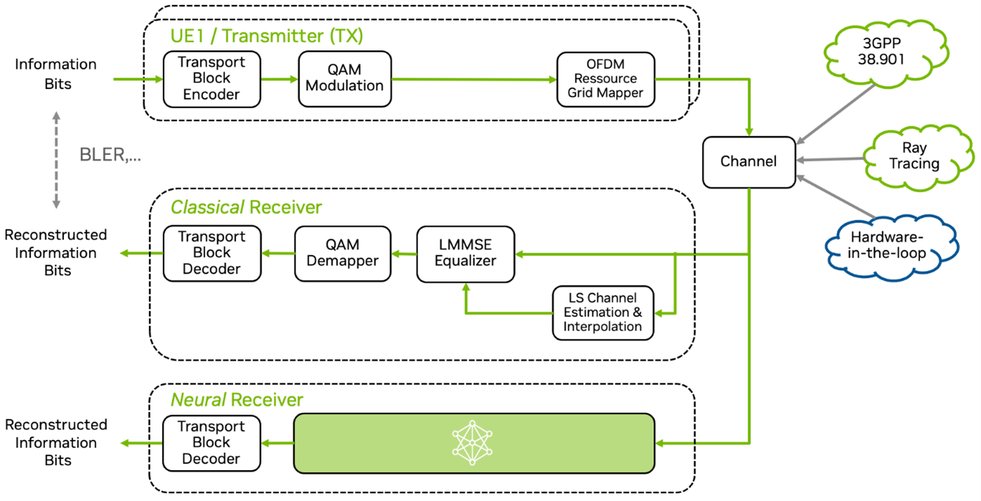
To reconstruct the transmitted information from a received signal, classical receivers perform a sequence of signal-processing steps. In a neural receiver, these handcrafted signal processing blocks are replaced by neural networks. In particular, only one neural network replaces channel estimation, equalization, and demapping (Figure 1).
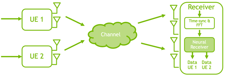
The NVIDIA prototype extends the concept of neural receivers by a multi-user MIMO component and enables 5G NR compatibility.
A specific focus of the neural network architecture is on the flexibility with respect to a varying number of users and a configurable number of subcarriers. This flexibility is a key enabler for practical deployment. The proposed architecture does neither require any retraining if additional users join or leave the network, nor if the number of allocated subcarriers or physical resource blocks (PRBs) change.
The neural network architecture itself is a combination of graph neural network (GNN) and convolutional neural network (CNN) layers. Intuitively, the GNN offers flexibility regarding a varying number of users as it enables easy reconfiguration. As a result, only 700K trainable weights are required to process an entire 5G slot, which is the entire time/frequency resource consisting of thousands of resource elements in the time-frequency OFDM grid.
The architecture design allows the receiver to be adapted to different system configurations. The number of physical resource blocks is also variable. In fact, the receiver is trained for four PRBs but is evaluated for 217 PRBs.
Sionna speaks 5G New Radio
For the rapid prototyping of 5G and beyond-5G research and training of such systems, NVIDIA developed Sionna, a GPU-accelerated framework for fully differentiable, link-level simulations. NVIDIA integrated a dedicated 5G NR module to enable 5G NR–compliant PUSCH simulations out-of-the-box with only a few lines of code.
As for any other Sionna component, the provided transmitter and receiver blocks are differentiable, and gradients can be back-propagated through the 5G transceiver components.
The following example shows 5G-compliant PUSCH simulations in a few lines of code.
# Create a PUSCH configuration with default settings
pusch_config = PUSCHConfig()

# Instantiate a PUSCHTransmitter from the PUSCHConfig
pusch_transmitter = PUSCHTransmitter(pusch_config)

# Create a PUSCHReceiver using the PUSCHTransmitter
pusch_receiver = PUSCHReceiver(pusch_transmitter)

# AWGN channel
channel = AWGN()

# Simulate transmissions over the AWGN channel
batch_size = 16
no = 0.1 # Noise variance

x, b = pusch_transmitter(batch_size) # Generate transmit signal and info bits

y = channel([x, no]) # Simulate channel output

b_hat = pusch_receiver([x, no]) # Recover the info bits

# Compute BER
print("BER:", compute_ber(b, b_hat).numpy()))
Hardware-in-the-loop testing and verification
To test the performance of such a neural receiver in a hardware-in-the-loop experiment, NVIDIA teamed up with Rohde & Schwarz, a premium supplier of test and measurement solutions.
Rohde & Schwarz combined its R&S SMW200A vector signal generator with two of its R&S SGT100A vector signal generators to create a 5G NR compliant uplink signal with a MIMO 2×4 configuration. Both users transmit simultaneously on the same time-frequency resources. Realistic channel conditions are simulated with the help of a channel emulator that applies different fading coefficients and noise to the users’ signals.
The resulting four RF channels are connected to the four phase-coherent inputs of the R&S MSR4 multi-purpose satellite receiver. The signals are captured, down-converted, and then digitized.
The resulting IQ samples are streamed to a server-based testing (SBT) architecture through four 10 Gbit/s Ethernet interfaces for further preprocessing while performing a fast Fourier transform (FFT) and cyclic prefix removal on the OFDM signal.
The post-FFT data is finally transferred to an NVIDIA workstation equipped with an NVIDIA RTX 4090 GPU, which performs inference of the trained neural receiver followed by channel decoding.
Trained in simulations, validated in the field
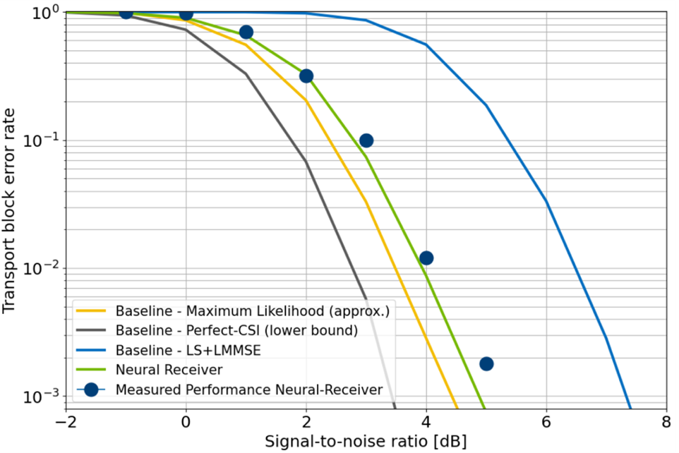
Figure 3 shows the block-error-rate performance of different receivers on a transport block level, that is, including the entire physical (PHY) layer effects. The blue dots show the results from the actual measurement while the solid lines are simulated with Sionna’s built-in channel models.
All systems are evaluated for the same scenario and the same input data, but for different receiver implementations.
- Perfect-CSI (grey): Perfectly known channel state information (CSI) at the receiver and maximum likelihood detection. This is obviously not realistic but provides a lower bound on the performance that practical systems can achieve.
- Maximum likelihood (orange): An approximation of maximum likelihood that achieves great performance but is not practical due to its high computational complexity.
- LS + LMMSE (blue): Least squares (LS) channel estimation with linear minimum mean squared error (LMMSE) detection. It can be considered a practical baseline due to its low complexity.
- Neural receiver (green): The neural receiver performs close to the maximum likelihood performance but with a significantly lower computational complexity.
One of the key accomplishments of this demo is to verify simulations from Sionna in a real hardware-in-the-loop scenario by using the R&S test and measurement equipment. As you can see, the performance matches well and only small performance degradation is introduced by the deployment on real hardware.
Why is Sionna so important for this experiment?
Neural receivers may overfit to a specific channel realization if training is done in the wrong way.
To avoid this effect, the receiver is trained with synthetic data based on Sionna’s built-in channel models. This means during training, the neural receiver sees many independent variations of the channel conditions such as random user speeds, different fading profiles, and various signal-to-noise ratios.
In particular, the receiver has been trained on a 3GPP UMi model with stochastic model parameters that are changed for every training iteration. This procedure avoids overfitting to a specific channel condition and the resulting neural receiver generalizes well to unseen channel realizations.
Towards 6G
Beyond pure block error-rate performance gains, our long-term vision is that these receivers can be fine-tuned for a specific environment. We consider the site-specific properties such as the expected user speed (a deployment close to a highway compared to low-speed indoor environments) or the expected maximum delay spread for the area of interest. As such, we envision base stations that can be continuously retrained, during low-load phases. We could improve their performance even after deployment in the field by simply updating their weights.
Going further, neural receivers can be seen as an enabler for a plethora of new physical layer concepts such as AI/ML-based waveforms or even semantic communications. While this research is still in an early stage and there is still a lot of work to be done, we are excited to show the potential of AI in the physical layer that may become an integral part of 6G communication systems.
To learn more, check out the Rohde & Schwarz video, Validating a Machine Learning-Based Neural Receiver with 5G NR Multiple MIMO Signals.
Acknowledgment and Disclaimer
This work has received financial support from the European Union under Grant Agreement 101096379 (CENTRIC). Views and opinions expressed are however those of the author(s) only and do not necessarily reflect those of the European Union or the European Commission (granting authority). Neither the European Union nor the granting authority can be held responsible for them.
