Ray and path tracing algorithms construct light paths by starting at the camera or the light sources and intersecting rays with the scene geometry. As objects are hit, new secondary rays are generated on these surfaces to continue the paths.
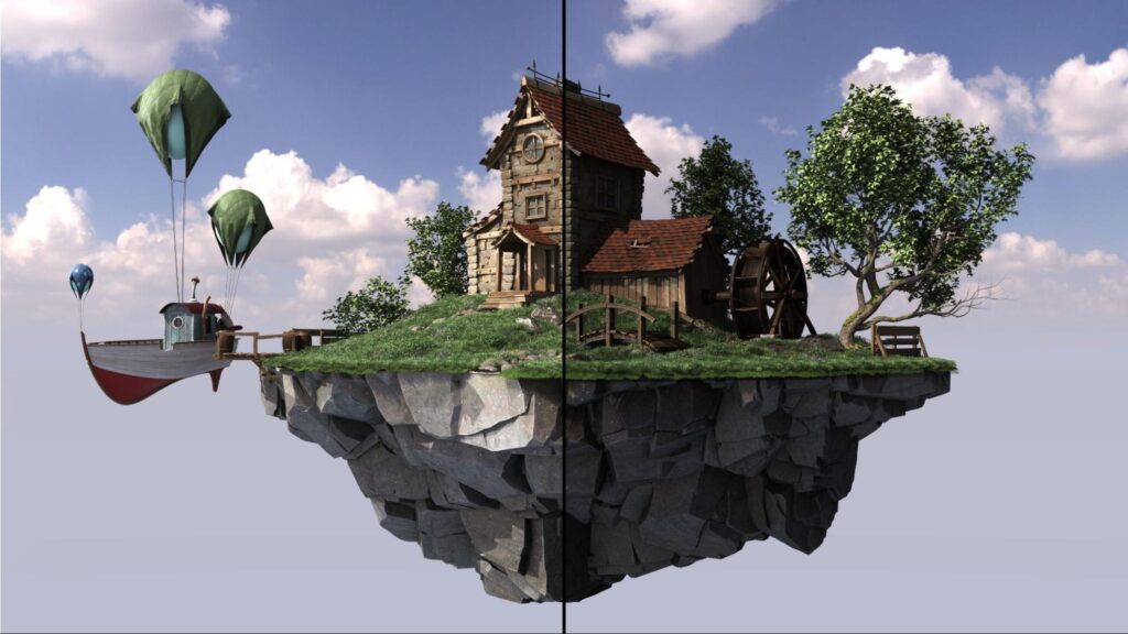
In theory, these secondary rays will not yield an intersection with the same triangle again, as intersections at a distance of zero are excluded by the intersection algorithm. In practice, however, the finite floating-point precision used in the actual implementation often leads to false-positive results, known as self-intersections (Figure 2). This creates artifacts, such as shadow acne, where the triangle sometimes improperly shadows itself (Figure 1).
Self-intersection can be avoided by explicitly excluding the same primitive from intersection using its identifier. In DirectX Raytracing (DXR) this self-intersection check would be implemented in an any-hit shader. However, forcing an any-hit invocation for all triangle hits comes at a significant performance penalty. Furthermore, this method does not deal with false positives against adjacent (near) coplanar triangles.
The most widespread solutions to work around the issue use various heuristics to offset the ray along either the ray direction or the normal. These methods are, however, not robust enough to handle a variety of common production content and may even require manual parameter tweaking on a per-scene basis, particularly in scenes with heavily translated, scaled or sheared instanced geometry. For more information, see Ray Tracing Gems: High-Quality and Real-Time Rendering with DXR and Other APIs.
Alternatively, the sources of the numerical imprecision can be numerically bounded at runtime, giving robust error intervals on the intersection test. However, this comes with considerable performance overhead and requires source access to the underlying implementation of the ray/triangle intersection routine, which is not possible in a hardware-accelerated API like DXR.
This post describes a robust offsetting method for secondary rays spawned from triangles in DXR. The method is based on a thorough numerical analysis of the sources of the numerical imprecision. It involves computing spawn points for secondary rays, safe from self-intersections. The method does not require modification of the traversal and ray/triangle intersection routines and can thus be used with closed-source and hardware-accelerated ray tracing APIs like DXR. Finally, the method does not rely on self-intersection rejection using an any-hit shader and has a fixed overhead per shading point.

Method overview
The spawn point of a secondary ray coincides with the hit point on a triangle of an incoming ray. The goal is to compute a spawn point as close as possible to the hit point in the triangle plane, while still avoiding self-intersections. Too close to the triangle may result in self-intersection artifacts, but too far away may push the spawn point past nearby geometry, causing light leaking artifacts.
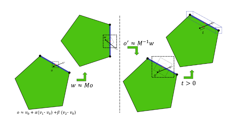
Figure 2 shows the sources of numerical error for secondary rays. In the user shader, the object-space hit point is reconstructed and transformed into world-space. During DXR ray traversal, the world-space ray is transformed back into object-space and intersected against triangles.
Each of these operations accumulates numerical errors, possibly resulting in self-intersections. This method computes a minimal uncertainty interval centered around the intended ray origin (red dot in Figure 2) on the triangle at each operation. The approximate ray origin (black dot in Figure 2) lies within this uncertainty interval. The ray origin is offset along the triangle normal beyond the final uncertainty interval to prevent self-intersections.
Hit point
Start by reconstructing the hit point and the geometric triangle normal in object-space (Listing 1).
precise float3 edge1 = v1 - v0;
precise float3 edge2 = v2 - v0;

// interpolate triangle using barycentrics
// add in base vertex last to reduce object-space error
precise float3 objPosition = v0 + mad(barys.x, edge1, mul(barys.y, edge2));
float3 objNormal = cross(edge1, edge2);
The hit point is computed by interpolating the triangle vertices v0, v1, and v2 using the 2D barycentric hit coordinates barys. Although it is possible to compute the interpolated hit point using two fused multiply-add operations, adding the base vertex v0 last reduces the maximum rounding error on the base vertex, which in practice dominates the rounding error in this computation.
Use the precise keyword to force the compiler to perform the computations exactly as specified. Enforced precise computation of the normal and the error bounds is not required. The effects of rounding errors on these quantities are vanishingly small and can safely be ignored for self-intersection.
Next, the object-space position is transformed into world-space (Listing 2).
const float3x4 o2w = ObjectToWorld3x4();

// transform object-space position
// add in translation last to reduce world-space error
precise float3 wldPosition;
wldPosition.x = o2w._m03 +
	mad(o2w._m00, objPosition.x,
mad(o2w._m01, objPosition.y,
mul(o2w._m02, objPosition.z )));
wldPosition.y = o2w._m13 +
mad(o2w._m10, objPosition.x,
mad(o2w._m11, objPosition.y,
mul(o2w._m12, objPosition.z )));
wldPosition.z = o2w._m23 +
mad(o2w._m20, objPosition.x ,
mad(o2w._m21, objPosition.y ,
mul(o2w._m22, objPosition.z )));
Instead of using the HLSL matrix mul intrinsic, write out the transformation. This ensures that the translational part \({m_{i,2}}\) of the transformation is added last. This again reduces the rounding error on the translation, which in practice tends to dominate the error in this computation.
Finally, transform the object-space normal to world-space and normalize it (Listing 3).
const float3x4 w2o = WorldToObject3x4();

// transform normal to world-space using
// inverse transpose matrix
float3 wldNormal = mul(transpose((float3x3)w2o), objNormal);

// normalize world-space normal
const float wldScale = rsqrt(dot(wldNormal, wldNormal));
wldNormal = mul(wldScale, wldNormal);

// flip towards incoming ray
if(dot(WorldRayDirection(), wldNormal) > 0)
wldNormal = -wldNormal;
To support transformations with uneven scaling or shear, the normals are transformed using the inverse transpose transformation. There is no need to normalize the object-space normal before the transformation. It is necessary to normalize again in world-space anyway. Because the inverse length of the world normal is needed again later to appropriately scale the error bounds, normalize manually instead of using the HLSL normalize intrinsic.
Error bounds
With an approximate world-space position and triangle normal, continue by computing error bounds on the computed position, bounding the maximum finite precision rounding error. It is necessary to account for the rounding errors in the computations in Listings 1 and 2.
It is also necessary to account for rounding errors that may occur during traversal (Figure 2). During traversal, DXR will apply a world-to-object transformation and perform a ray-triangle intersection test. Both of these are performed in finite precision and thus introduce rounding errors.
Start by computing a combined object-space error bound, accounting both for the rounding errors in Listing 1 and rounding errors due to the DXR ray-triangle intersection test (Listing 4).
const float c0 = 5.9604644775390625E-8f;
const float c1 = 1.788139769587360206060111522674560546875E-7f;

// compute twice the maximum extent of the triangle
const float3 extent3 = abs(edge1) + abs(edge2) +
   abs(abs(edge1) - abs(edge2));
const float extent = max(max(extent3.x, extent3.y), extent3.z);

// bound object-space error due to reconstruction and intersection
float3 objErr = mad(c0, abs(v0), mul(c1, extent));
Note that the error on the triangle intersection is bounded by the maximum triangle extent along the three dimensions. A rigorous proof for this bound goes beyond the scope of this post. To provide an intuitive justification, common ray-triangle intersection algorithms reorient the triangle into ’ray space’ (by subtracting the ray origin) before performing the intersection test. In the context of self-intersection, the ray origin lies on the triangle. Thus, the magnitude of the remaining triangle vertices in this ray space is bounded by the extent of the triangle along each dimension.
Furthermore, these intersection algorithms project the triangle into a 2D plane. This projection causes errors along one dimension to bleed over into the other dimensions. Therefore, take the maximum extent along all dimensions, instead of treating the error along the dimensions independently. The exact bound on the ray-triangle intersection test will be hardware-specific. The constant c1 is tuned for NVIDIA RTX hardware, but may require some adjusting on different platforms.
Error bounds for custom intersection primitives depend on the implementation details of their Intersection shader. See Advanced Linear Algebra: Foundations to Frontiers for a thorough introduction to finite precision rounding error analysis.
Next, compute the world-space error bound due to the transformation of the hit point from object-space to world-space (Listing 5).
// bound world-space error due to object-to-world transform
const float c2 = 1.19209317972490680404007434844970703125E-7f;
float3 wldErr = mad(c1, mul(abs((float3x3)o2w), abs(objPosition)),
     mul(c2, abs(transpose(o2w[3]))));
That leaves the rounding errors in the world-to-object transformation performed by DXR during ray traversal (Listing 6).
// bound object-space error due to world-to-object transform
objErr = mad(c2, mul(abs(w2o), float4(abs(wldPosition), 1)), objErr);
Like the ray-triangle intersection test, the rounding error in the world-to-object transformation depends on the hardware. The constant c2 is conservative and should suffice for the various ways of implementing the vector matrix multiplication.
The finite precision representation of the world-to-object transformation matrix and its inverse are not guaranteed to match exactly. In the analysis, the error in the representation can be attributed to one or the other. Because the object-to-world transformation is performed in user code, the errors are best attributed to the object-to-world transformation matrix, enabling tighter bounds.
Offset
The previous section explained how to compute bounds on the rounding errors for secondary ray construction and traversal. These bounds yield an interval around the approximate, finite precision ray origin. The intended, full-precision ‘true’ ray origin is guaranteed to lie somewhere in this interval.
The true triangle passes through the true ray origin, so the triangle also passes through this interval. Figure 3 shows how to offset the approximate origin along the triangle normal to guarantee it lies above the true triangle, thus preventing self-intersections.

The error bound ∆ is projected onto the normal n to obtain an offset δ along the normal
\({\delta = \frac{\Delta \cdot {abs}\left(n\right)}{n \cdot n}}\)
Rounding errors on the normal are of similar magnitude as rounding errors on the computation of the error bounds and offset themselves. These are vanishingly small and can in practice be ignored. Combine the object and world-space offsets into a single world-space offset along the world-space normal (Listing 7).
// compute world-space self-intersection avoidance offset
float objOffset = dot(objErr, abs(objNormal));
float wldOffset = dot(wldErr, abs(wldNormal));

wldOffset = mad(wldScale, objOffset, wldOffset);
Use the already normalized world-space normal \({\bar{n}_w}\) from Listing 3. The world-space offset \({\delta_w}\) simplifies to \(\delta_w = \Delta \cdot {abs}\left( \bar{n}_w \right)\). The object-space offset \({\delta_o}\) along the object-space normal \({n_o}\) needs to be transformed into world-space as \({\delta_o M n_o}\).
Note, however, that the transformed object-space offset is not necessarily parallel to the world-space normal \({n_w}\). To obtain a single combined offset along the world-space normal, project the transformed object-space offset onto the world-space normal, as \({\delta_o M n_o \cdot n_w}\). Using that \({n_w = M^{-T} n_o}\) this simplifies to:
\({\delta_o M n_o \cdot M^{-T} n_o = \delta_o \left( M n_o \right)^T M^{-T} n_o = \delta_o n_o \cdot M^T M^{-T} n_o = \delta_o n_o \cdot n_o = \Delta \cdot {abs}\left(n\right)}\)
Finally, use the computed offset to perturb the hit point along the triangle normal (Listing 8).
// offset along the normal on either side.
precise float3 wldFront = mad( wldOffset, wldNormal, wldPosition);
precise float3 wldBack  = mad(-wldOffset, wldNormal, wldPosition);
This yields front and back spawn points safe from self-intersection. The derived error bounds (and thus offsets) neither depend on the incoming ray direction nor the outgoing secondary ray direction. It is therefore possible to reuse the same spawn points for all secondary rays originating from this hit point. All reflection rays should use the front spawn point while transmission rays should use the back spawn point.
Object-to-world and world-to-object transformations of the direction also cause rounding errors in the ray direction. At extreme grazing angles, these rounding errors may cause it to flip sides, orienting it back towards the triangle. The offsetting method in this post does not protect against such rounding errors. It is generally advised to filter out secondary rays at extreme angles.
Alternatively, similar error bounds can be derived on the ray direction transformations. Offsetting the ray direction along the triangle normal (as for the ray origin) can then guarantee its sidedness. However, as the reflectance distribution of common BRDF models tends towards zero at grazing angles, this problem can be safely ignored in many applications.
Object space
As seen in Listing 4, the offset grows linearly in the triangle extent and the magnitude of the triangle base vertex in object-space. For small triangles, the rounding error in the base vertex will dominate the object-space error (Figure 2). It is thus possible to reduce the object-space error by repositioning geometry in object-space, centering it around the object-space origin to minimize the distance to the origin. For geometry with extremely large triangles, such as ground planes, it may be worthwhile to tessellate the geometry and further reduce the rounding errors in the triangle extent.
Camera space
As seen in Listings 5 and 6, the magnitude of the offset will grow linearly with the magnitudes of the world-space position. The proportionality constant c2 is approximately 1 ulps. Instanced geometry at a distance \({d}\) from the scene origin in world-space will have a maximum rounding error in the order of \({d2^{-22}}\), or 1 mm of offset for every 4 km distance. The offset magnitudes also scale linear with the triangle extent and object-space position.
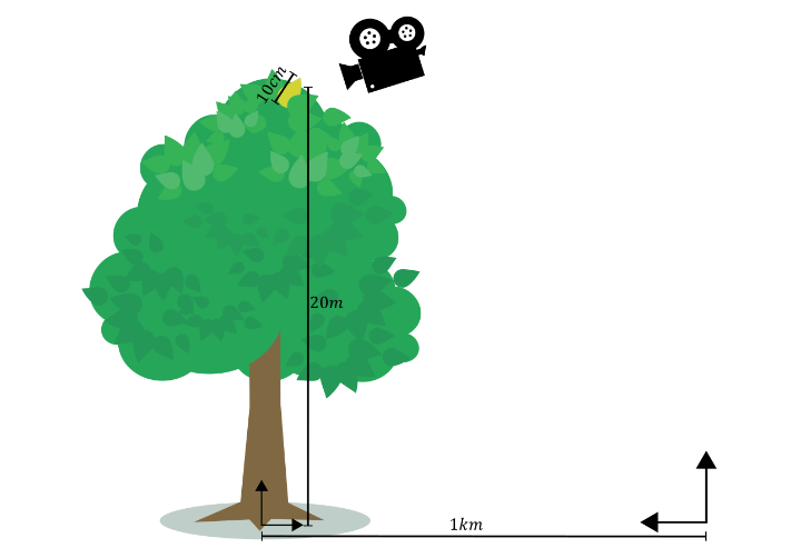
For an example secondary ray in Figure 4 spawned on a leaf of 10 cm, in a tree of 20 m (object-space origin at the root) 1 km away from the world space origin, the offset magnitudes due to the triangle extent, object-space position, and world-space position will be in the order of 45 nm, 4 µm, and 0.25 mm, respectively. In practice, rounding errors in the world-space position tend to dominate all rounding errors. This is particularly true for large scenes of relatively small objects.
Note that the error is proportional to the world-space distance to the scene origin, not the scene camera. Consequently, if the camera is far away from the scene origin, the offsets for rays spawned from nearby geometry may become prohibitively large, resulting in visual artifacts.
This problem can be reduced by translating the entire scene into camera space. All instances are repositioned so the camera origin coincides with the world-space origin. Consequently, the distance \({d}\) becomes the distance to the camera in this camera space and the offset magnitudes will be proportional to the distance to the camera. Rays spawned from geometry near the camera will enjoy relatively small offsets, reducing the likelihood of visual artifacts due to offsetting.
Connection rays
This discussion has so far focused on offsetting of the ray origin to prevent self-intersection at the origin. Ray and path tracing algorithms also trace rays to evaluate visibility between two points on different triangles, such as shadow rays connecting a shading point and a light source.
These rays may suffer from self-intersection on either end of the ray. It is necessary to offset both ends to avoid self-intersections. The offset for the endpoint is computed in a similar fashion as for the ray origin, but using the object-to-world and world-to-object transformation matrices, barycentric and triangle vertices of the endpoint and using the connection ray direction as the incoming ray direction.
Contrary to scattering rays, it is necessary to account for rounding errors in the world-to-object ray direction transform during traversal. Theoretically, it is also necessary to account for additional rounding error in the ray-triangle intersection test because the ray origin does not lie on the endpoint triangle. However, this additional error scales sublinearly with the world-to-object error, so for simplicity these errors are implicitly combined.
For the endpoint, the world-to-object transformation error computation in Listing 6 is replaced by (Listing 9).
// connection ray direction
precise float3 wldDir = wldEndPosition - wldOrigin;

// bound endpoint object-space error due to object-to-world transform
float4 absOriginDir = (float4)(abs(wldOrigin) + abs(wldDir), 1);
objEndErr = mad(c2, mul(abs(w2oEnd), absOriginDir), objEndErr);
Here, wldOrigin is the connection ray origin in world-space. In DXR, rays are defined using an origin and direction. Instead of offsetting the endpoint and recomputing the ray direction, apply the offset directly to the world-space direction. For endpoint offsetting, Listing 8 thus becomes Listing 10.
// offset ray direction along the endpoint normal towards the ray origin
wldDir = mad(wldEndOffset, wldEndNormal, wldDir) ;

// shorten the ray tmax by 1 ulp
const float tmax = 0.99999994039f;
Shorten the ray length by 1 ulp to account for rounding errors in the direction computation.
In practice, a simpler approach of using a cheap approximate offsetting heuristic in combination with identifier-based self-intersection rejection is often sufficient to avoid endpoint self-intersection.The approximate offsetting will avoid most endpoint self-intersections, with identifier-based hit rejection taking care of the remaining self-intersections.
For secondary scatter rays, avoid identifier based self-intersection rejection, as it requires invoking an any-hit shader for every intersection along the ray, adding significant performance overhead. However, for visibility rays, the additional performance overhead of endpoint identifier-based hit rejection is minimal.
For visibility rays using the RAY_FLAG_ACCEPT_FIRST_HIT_AND_END_SEARCH flag there will always be at most two additional reported hits: the rejected endpoint self-intersection and any occluder terminating traversal.
For visibility rays not using the RAY_FLAG_ACCEPT_FIRST_HIT_AND_END_SEARCH flag, self-intersections can be rejected in the closest-hit shader instead of the any-hit shader. If the visibility ray invokes the closest-hit shader for the endpoint triangle, no closer hit was found and thus the hit should simply be treated as a miss in the closest-hit shader.
Conclusion
The method presented in this post offers a robust and easy-to-use solution for self-intersections of secondary rays. The method applies a minimal conservative offset, resolving self-intersection artifacts while reducing light leaking artifacts. Moreover, the method has minimal runtime overhead and integrates easily in common shading pipelines. While this post describes an HLSL implementation for DXR, the approach translates easily to GLSL for Vulkan and CUDA for OptiX.
For more information, visit NVIDIA/self-intersection-avoidance on GitHub for HLSL and GLSL sample implementations. And check out the OptiX Toolkit ShaderUtil Library for a ready-to-use OptiX header library for self-intersection avoidance.
