The evolution of a production-tested high performance ray tracing API

There has been a recent shift in high-performance API design towards providing lower-level control of resource management and execution scheduling. This design evolution allows experienced developers to be in full control of their application while still leveraging the benefits of highly optimized APIs. The lower level of control also provides developers with increased flexibility so that the API usage can better fit the needs of their application. Examples of this shift can be seen in the current DirectX and Vulkan SDKs. With the latest 7.0 release, OptiX joins this evolution, offering direct control of core functionalities once managed internally by the OptiX runtime, including host and device-side memory allocations, multi-GPU work distribution, and asynchronous scheduling.
The NVIDIA RTX Ray Tracing Ecosystem
There are multiple choices in ray tracing SDKs which leverage the NVIDIA RTX technology stack and special purpose ray tracing RTCore hardware; Microsoft’s DXR API provides ray-tracing functionality in a Direct X environment, the VK_NV_ray_tracing extension adds similar support to the Vulkan API, and NVIDIA’s OptiX SDK brings ray tracing to the CUDA world. The first two of these APIs are focused on tight integration into real-time applications and therefore are constrained in their feature sets. OptiX, on the other hand, targets production-quality rendering, offering built-in support for advanced features such as motion-blur and multi-level transform hierarchies.
The OptiX API has been used in a wide variety of applications for years. It is battle-tested and has been a key tool in bringing GPU ray tracing to the world. Since the release of NVIDIA’s RTCore hardware, there has been an increasing desire to apply GPU-acceleration to larger and more complicated ray tracing workloads, such as final-frame rendering for feature films and interactive preview of very large datasets. To this end, we have redesigned the OptiX API to give more flexibility in implementing such applications. This new API is lower level, similar to the level of abstraction of DXR or Vulkan ray tracing, but retains many of the key concepts that have always existed in OptiX.
At SIGGRAPH 2019 NVIDIA released two new versions of the OptiX API: OptiX 7.0, which contains the new low-level API; and OptiX 6.5, which is an update to the classic API. The table below provides a comparison of these four ray-tracing packages.
| Microsoft DXR | Vulkan | OptiX 6 | OptiX 7 | |
| Operating System | Windows | Windows, Linux | Windows, Linux | Windows, Linux |
| RTX shader model | ✓ | ✓ | ✓ | ✓ |
| Custom primitives | ✓ | ✓ | ✓ | ✓ |
| Shader languages | HLSL DXIL | HLSL, GLSL SPIR-V | CUDA, OSL, MDL PTX | CUDA, OSL, MDL PTX |
| Motion blur | ✓ | ✓ | ||
| Multi-level traversal | ✓ | ✓ | ||
| Fully thread safe | ✓ | ✓ | ✓ | |
| Async | ✓ | ✓ | Limited | ✓ |
| Memory management | Explicit | Explicit | Implicit | Explicit |
| Multi GPU | Explicit | Explicit | Implicit | Explicit |
| NVLinkScaling | Explicit | Explicit | Implicit | Explicit |
| AS Builds | Explicit | Explicit | Implicit | Explicit |
| Shader Binding Table (SBT) | Explicit | Explicit | Implicit | Explicit |
| GPU Support | Volta, Turing | Volta, Turing | Maxwell, Pascal, Volta, Turing | Maxwell, Pascal, Volta, Turing |
Comparison of feature-sets for RTX-ready APIs. Features marked as implicit are managed automatically by the underlying runtime and are not exposed for explicit control by client applications.
The OptiX 7 API
The NVIDIA OptiX 7 API is a CUDA-centric API that is easily invoked by a CUDA-based application. The API is designed to be stateless, multi-threaded, asynchronous, supports a lightweight representation for scenes, and is fully thread-safe.
OptiX Device Code API
Like the classic OptiX API, device code is organized into several types of programs, which are composed, along with OptiX’s internal scheduling algorithms and BVH traversal programs, into a full ray-tracing kernel.

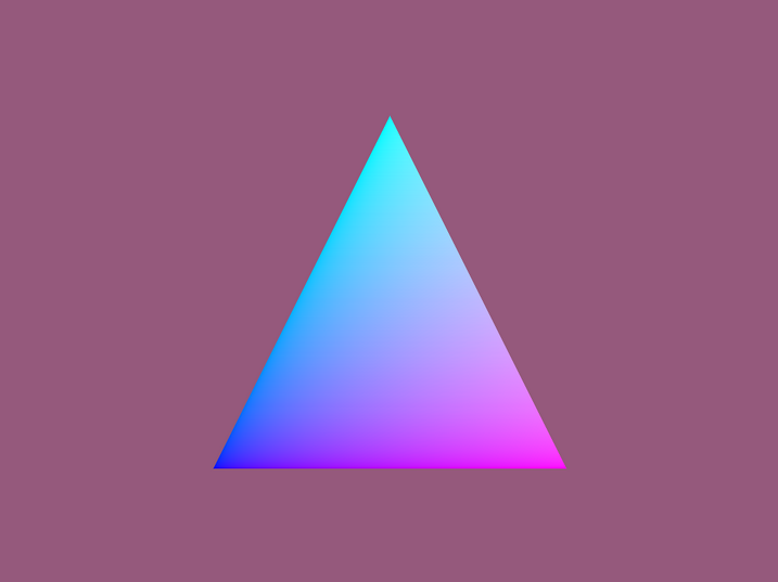
We demonstrate the device-side OptiX API via a simple sample program which renders a single triangle with trivial shading. The full source for this program can be found in the OptiX 7 SDK in the optixTriangle example application.
The Ray-Generation Program
The ray-generation program is the entry point to execution on the device when optixLaunch is called on the host. In our example, the ray-generation function maps its index in the launch grid to a pixel in the virtual screen, traces a ray from the camera through the pixel, and records the results in an output raster.
// This is a struct used to communicate launch parameters which are constant
// for all threads in a given optixLaunch call.
struct Params
{
    uchar4*  image;
    unsigned int  image_width;
    unsigned int  image_height;
    float3   cam_eye;
    float3   cam_u, cam_v, cam_w;
    OptixTraversableHandle handle;
};

extern "C"
{
__constant__ Params params;
}

// Note the __raygen__ prefix which marks this as a ray-generation
// program function
extern "C" __global__ void __raygen__rg()
{
    // Lookup our location within the launch grid
    const uint3 idx = optixGetLaunchIndex();
    const uint3 dim = optixGetLaunchDimensions();

    // Map our launch idx to a screen location and create a ray from
    // the camera location through the screen
    float3 ray_origin, ray_direction;
    computeRay( idx, dim, ray_origin, ray_direction );

    // Trace the ray against our scene hierarchy
    unsigned int p0, p1, p2;
    optixTrace(
        params.handle,
        ray_origin,
        ray_direction,
        0.0f,   // Min intersection distance
        1e16f,  // Max intersection distance
        0.0f,   // ray-time -- used for motion blur
        OptixVisibilityMask( 255 ), // Specify always visible
        OPTIX_RAY_FLAG_NONE,
        0,      // SBT offset -- See SBT discussion
        0,      // SBT stride -- See SBT discussion
        0,      // missSBTIndex -- See SBT discussion
        p0, p1, p2 ); // These 32b values are the ray payload

    // Our results were packed into opaque 32b registers
    float3 result;
    result.x = int_as_float( p0 );
    result.y = int_as_float( p1 );
    result.z = int_as_float( p2 );

    // Record results in our output raster
    params.image[idx.y * params.image_width + idx.x] = make_color( result );
}
This is quite similar to classic OptiX with a few important differences:
- We no longer use rtVariables and rtBuffers to pass inputs into this or any other type of OptiX program. Instead, we use a launch param struct for constant global inputs and a shader binding table (SBT) for per-program inputs. The SBT is not used in this particular program, so we will discuss it further in a following section.
- A function name prefix is required to denote the OptiX program type, __raygen__ in this case.
- A per-ray-data structure is no longer used to communicate across trace boundaries. Instead the caller can use up to eight 32-bit opaque registers to associate data with the ray. If more than 32 bytes of data is needed, a pointer to a struct may be passed in two of the registers. Using registers directly here allows for maximum efficiency.
The Intersection Program
When optixTrace is called, the specified ray traverses the acceleration data structure provided. On NVIDIA RTX GPUs, this can be executed on special purpose hardware to allow exceptionally efficient traversal of the acceleration structure.
When acceleration structure leaf nodes are encountered, ray-primitive intersection testing is performed. Intersection programs are used to describe custom geometric primitive intersection. Additionally, OptiX has built-in intersection support for triangles. We take advantage of this support in our example and do not use an intersection program at all.
While any surface can be represented with triangles, there are some tradeoffs that do cause custom primitives to be useful in some situations. For example:
- Some datasets can be represented more compactly with implicit representations. A sphere can be represented by a scalar radius and a 3D position within a single primitive. A mesh representing a sphere will use much more GPU memory and represent many primitives in an acceleration data structure.
- Triangle meshes only approximate curved surfaces. This is fine in most cases, but can cause issues if the mesh tessellation is not fine enough for a given use-case.
- Data may need to be shared between OptiX and another library with a native representation for geometry.
However, triangles have two very large advantages: they are the most common geometric representation in computer graphics and, due to NVIDIA’s special purpose hardware for intersecting triangles, they are the most efficient primitive to intersect on RTX GPUs. When possible, triangle geometry is usually the most efficient choice, often by a large margin.
Custom intersection programs are also used in previous versions of OptiX, but a few things are new in OptiX 7:
- rtVariable attributes are no longer used to communicate information downstream from intersection programs. Instead, up to eight registers can be used to pass back intersection attributes. Usually the minimum number of attributes required should be used, and calculation of additional geometric information deferred to the closest-hit program (see next section).
- rtPotentialIntersection and rtReportIntersection have been combined into a single API call: optixReportIntersection.
The Closest-Hit Program
After ray-traversal is completed, if an intersection was found, the closest-hit program is invoked. This program typically calculates derived geometric quantities resulting from intersection, performs material shading, and passes the results back to the ray-generation program. In some applications, shading is deferred to the ray-generation program itself.
In the example closest-hit program, we simply visualize the triangle’s barycentric coordinates.
extern "C" __global__ void __closesthit__ch()
{
    // When built-in triangle intersection is used, a number of fundamental
    // attributes are provided by the OptiX API, including barycentric
    // coordinates.
    const float2 barycentrics = optixGetTriangleBarycentrics();

    // Convert to color and assign to our payload outputs.
    const float3 c = make_float3( barycentrics, 1.0f );
    optixSetPayload_0( float_as_int( c.x ) );
    optixSetPayload_1( float_as_int( c.y ) );
    optixSetPayload_2( float_as_int( c.z ) );
}
The Miss Program
Following ray-traversal, if an intersection was not found the miss program is executed. The miss program is often used to provide a background or environment shader. This example’s miss program is trivial, but it does demonstrate one very important concept in the new OptiX API – the shader binding table (SBT).
extern "C" __global__ void __miss__ms()
{
    MissData* miss_data =
    reinterpret_cast<MissData*>( optixGetSbtDataPointer() );
    setPayload( miss_data->bg_color );
}
The shader binding table provides a data block per instance of an optix program and is used here to pass in a background color for use by the miss program. The optixGetSbtDataPointer call returns a pointer to the first byte of the data block assigned to this particular program and ray type.
Other Program Types
There are three additional types of OptiX programs not demonstrated in this example:
- Any-hit programs: Invoked during traversal when a potential primitive intersection is encountered. This allows the application to reject intersections, terminate traversal, or gather information about primitives encountered during traversal. Care should be taken when using any-hit programs as they come with a high performance cost on RTX hardware.
- Exception programs: If enabled, OptiX exceptions may be triggered during a launch. The exception program allows an application to catch and handle these exceptions.
- Callable programs: Used in place of function pointers or virtual functions, callable programs allow the application to plug-in functionality to a shader at runtime. A common use case is to represent a procedural texture operation with a callable program which might, for example, resolve to Perlin noise or to a checkerboard pattern at runtime.
Many details of the various OptiX device programs have been omitted here. Full documentation can be found in the OptiX Programming Guide and more complex usage examples can be found in the OptiX SDK.
Host Code
The OptiX host API has been simplified, allowing many operations which were managed by the OptiX library to be under the full control of the client application. Examples of these explicitly controlled operations include memory management, host-side multi-threading, multi-GPU work distribution, and CUDA stream management. OptiX objects are now light weight handles with little or no underlying state.
Now let’s take a look at how the host-side API is used to set up the above device code for optixSimpleTriangle.
Device Contexts
An OptiX 7 device context is bound to a single GPU and associated with a single CUDA context. Applications wishing to leverage multiple GPUs in a system may create multiple device contexts and use them to invoke independent launches per device. Below is code to create an OptixDeviceContext bound to the primary CUDA context.
// Initialize CUDA with a no-op call to the the CUDA runtime API
cudaFree( 0 );

// Initialize the OptiX API, loading all API entry points
optixInit();

// Specify options for this context. We will use the default options.
OptixDeviceContextOptions options = {};

// Associate a CUDA context (and therefore a specific GPU) with this
// device context
CUcontext cuCtx = 0; // NULL means take the current active context

OptixDeviceContext context = nullptr;
optixDeviceContextCreate( cuCtx, &options, &context );
For the sake of brevity, we omit any error code checking on CUDA and OptiX API calls. The full optixSimpleTriangle sample source uses error checking macros on all API functions. Also note the idiomatic zero-initialization of the input struct OptixDeviceContextOptions. A good practice is to zero-initialize all OptiX input structs to mark all fields as default, then to selectively override the fields to be used.
Acceleration Structures
The creation of Acceleration structures has undergone significant changes in the new OptiX API:
- The client is responsible for explicitly allocating all necessary device memory for the structure itself and its inputs. In prior releases, the OptiX library managed all memory for the acceleration struct and usually allocated memory for the geometric inputs as well via the RTbuffer mechanism.
- Classic OptiX deferred building of acceleration structures to the first launch. Now the client app itself triggers all launches explicitly. This gives added flexibility in how builds are scheduled via multi-threading and allows interleaving of builds with other work, such as loading assets from disk.
For our sample application, we will build a geometry acceleration structure (GAS) for a single triangle. The output of the build phase is a traversable handle, which can be passed to device code and then used as the target for an optixLaunch call.
// Specify options for the build. We use default options for simplicity.
OptixAccelBuildOptions accel_options = {};
accel_options.buildFlags = OPTIX_BUILD_FLAG_NONE;
accel_options.operation = OPTIX_BUILD_OPERATION_BUILD;

// Triangle build input: simple list of three vertices
const std::array<float3, 3> vertices =
{ {
    { -0.5f, -0.5f, 0.0f },
    {  0.5f, -0.5f, 0.0f },
    {  0.0f,  0.5f, 0.0f }
} };

// Allocate and copy device memory for our input triangle vertices
const size_t vertices_size = sizeof( float3 )*vertices.size();
CUdeviceptr d_vertices=0;
cudaMalloc( reinterpret_cast<void**>( &d_vertices ), vertices_size ) );
cudaMemcpy( reinterpret_cast<void*>( d_vertices ),
      vertices.data(),
      vertices_size,
      CudaMemcpyHostToDevice );

// Populate the build input struct with our triangle data as well as
// information about the sizes and types of our data
const uint32_t triangle_input_flags[1] = { OPTIX_GEOMETRY_FLAG_NONE };
OptixBuildInput triangle_input = {};
triangle_input.type   = OPTIX_BUILD_INPUT_TYPE_TRIANGLES;
triangle_input.triangleArray.vertexFormat = OPTIX_VERTEX_FORMAT_FLOAT3;
triangle_input.triangleArray.numVertices = vertices.size();
triangle_input.triangleArray.vertexBuffers= &d_vertices;
triangle_input.triangleArray.flags = triangle_input_flags;
triangle_input.triangleArray.numSbtRecords= 1;

// Query OptiX for the memory requirements for our GAS
OptixAccelBufferSizes gas_buffer_sizes;
optixAccelComputeMemoryUsage(
     context,         // The device context we are using
     &accel_options,
     &triangle_input, // Describes our geometry
     1,               // Number of build inputs, could have multiple
     &gas_buffer_sizes );

// Allocate device memory for the scratch space buffer as well
// as the GAS itself
CUdeviceptr d_temp_buffer_gas;
cudaMalloc( reinterpret_cast<void**>( &d_temp_buffer_gas ),
    gas_buffer_sizes.tempSizeInBytes );
cudaMalloc( reinterpret_cast<void**>( &d_gas_output_buffer ),
    gas_buffer_sizes.outputSizeInBytes );

// Now build the GAS
OptixTraversableHandle gas_handle = nullptr;
optixAccelBuild(
    context,
    0,           // CUDA stream
    &accel_options,
    &triangle_input,
    1,           // num build inputs
    d_temp_buffer_gas,
    gas_buffer_sizes.tempSizeInBytes,
    d_gas_output_buffer,
    gas_buffer_sizes.outputSizeInBytes,
    &gas_handle, // Output handle to the struct
    nullptr,     // emitted property list
    0 );         // num emitted properties

// We can now free scratch space used during the build
cudaFree( reinterpret_cast<void*>( d_temp_buffer_gas ) );
In most cases, we would now want to perform an additional compaction step using optixAccelCompact. This operation allows resizing of the buffers from the conservative estimate given by optixAccelComputeMemoryUsage to the actual size used for the final acceleration structure build.
Modules, Program Groups, and Pipelines
Now that we have created our geometry, we need to specify the OptiX programs we want to use to render it. The CUDA code for our programs first needs to be converted to NVIDIA’s intermediate code representation, PTX, usually via the CUDA nvcc compiler. The programs in PTX form are then compiled into OptixModules. One or more modules are used to create an OptixProgramGroup. Those program groups are then linked into an OptixPipeline, enabling them to work together on the GPU. This is similar to the compile-and-link process commonly found in standard compiler toolchains.
Here is our code for creating an OptixModule from a single source:
// Default options for our module. OptixModuleCompileOptions module_compile_options = {};


// Pipeline options must be consistent for all modules used in a
// single pipeline
OptixPipelineCompileOptions pipeline_compile_options = {};
pipeline_compile_options.usesMotionBlur = false;

// This option is important to ensure we compile code which is optimal
// for our scene hierarchy. We use a single GAS – no instancing or
// multi-level hierarchies
pipeline_compile_options.traversableGraphFlags =
 OPTIX_TRAVERSABLE_GRAPH_FLAG_ALLOW_SINGLE_GAS;

// Our device code uses 3 payload registers (r,g,b output value)
pipeline_compile_options.numPayloadValues = 3;

// This is the name of the param struct variable in our device code
pipeline_compile_options.pipelineLaunchParamsVariableName = "params";

const std::string ptx = getPtxString( "optixTriangle.cu" );
size_t sizeof_log = sizeof( log );

OptixModule module = nullptr; // The output module
optixModuleCreateFromPTX(
    context,
    &module_compile_options,
    &pipeline_compile_options,
    ptx.c_str(),
    ptx.size(),
    log,
    &sizeof_log,
    &module );
Once we have one or more modules, we can create program groups to associate OptiX programs with their input parameters. This association is created in a shader binding table (SBT) record. The SBT is a device memory array of these records, with each record consisting of two parts: a header and a data block. The header is opaque to the client application and contains the information necessary for OptiX to identify programs during traversal, such as which ray-generation program is used by a given pipeline. The data block is opaque to OptiX and is used by the client application to specify program parameters, such as material properties for a closest-hit program.
There are several types of program groups, but for our example we will only be using a ray-generation group, a miss group, and a hit group. Hit groups are unique in that they may contain multiple programs associated with evaluating geometry hits; an intersection program, a closest-hit program, and an any-hit program. A hit group is roughly analogous to a GeometryInstance in the original OptiX interface. In our simple example, we require only a closest-hit program since we are using built-in triangle functionality and simple shading.
OptixProgramGroup raygen_prog_group = nullptr;
OptixProgramGroup miss_prog_group = nullptr;
OptixProgramGroup hitgroup_prog_group = nullptr;

OptixProgramGroupOptions program_group_options = {};
OptixProgramGroupDesc raygen_prog_group_desc = {};
raygen_prog_group_desc.kind = OPTIX_PROGRAM_GROUP_KIND_RAYGEN;
raygen_prog_group_desc.raygen.module = module;
raygen_prog_group_desc.raygen.entryFunctionName = "__raygen__rg";
size_t sizeof_log = sizeof( log );
optixProgramGroupCreate(
    context,
    &raygen_prog_group_desc,
    1, // num program groups
    &program_group_options,
    log,
    &sizeof_log,
    &raygen_prog_group );

OptixProgramGroupDesc miss_prog_group_desc = {};
miss_prog_group_desc.kind = OPTIX_PROGRAM_GROUP_KIND_MISS;
miss_prog_group_desc.miss.module = module;
miss_prog_group_desc.miss.entryFunctionName = "__miss__ms";
sizeof_log = sizeof( log );
optixProgramGroupCreate(
    context,
    &miss_prog_group_desc,
    1, // num program groups
    &program_group_options,
    log,
    &sizeof_log,
    &miss_prog_group );

OptixProgramGroupDesc hitgroup_prog_group_desc = {};
hitgroup_prog_group_desc.kind = OPTIX_PROGRAM_GROUP_KIND_HITGROUP;
hitgroup_prog_group_desc.hitgroup.moduleCH = module;
hitgroup_prog_group_desc.hitgroup.entryFunctionNameCH = "__closesthit__ch";
// We could also specify an any-hit and/or intersection program here
sizeof_log = sizeof( log );
optixProgramGroupCreate(
    context,
    &hitgroup_prog_group_desc,
    1, // num program groups
    &program_group_options,
    log,
    &sizeof_log,
    &hitgroup_prog_group );
Finally, we can link our program groups into an OptiX pipeline. A pipeline corresponds to a an entry point in the classic OptiX API. You can compose multiple pipelines sharing program groups if multiple different render passes are desired.
OptixProgramGroup program_groups[] =
{
    raygen_prog_group,
    miss_prog_group,
    Hitgroup_prog_group
};

OptixPipelineLinkOptions pipeline_link_options = {};
pipeline_link_options.maxTraceDepth = 1;
pipeline_link_options.debugLevel = OPTIX_COMPILE_DEBUG_LEVEL_FULL;
size_t sizeof_log = sizeof( log );

OptixPipeline pipeline = nullptr;
optixPipelineCreate(
    context,
    &pipeline_compile_options,
    &pipeline_link_options,
    program_groups,
    sizeof( program_groups ) / sizeof( program_groups[0] ),
    log,
    &sizeof_log,
    &pipeline );
The Shader Binding Table
We now have the program groups needed to populate the record headers in our SBT. The SBT mechanism is very flexible, allowing for many different setups depending on the needs of a given application. For example, an application may specify different programs and data to be used for differing ray types (eg, shadow rays, camera rays, or ambient occlusion rays) or might specify different hit-groups per-triangle in a mesh. Our example is very simple with a single record per program, with only the miss program utilizing the data block of its SBT record.
// These structs represent the data blocks of our SBT records
struct RayGenData   { // No data needed };
struct HitGroupData { // No data needed };
struct MissData     { float3 bg_color;  };

// SBT record with an appropriately aligned and sized data block
template
struct SbtRecord
{
    __align__( OPTIX_SBT_RECORD_ALIGNMENT )
    char header[OPTIX_SBT_RECORD_HEADER_SIZE];
    T data;
};

typedef SbtRecord<RayGenData>   RayGenSbtRecord;
typedef SbtRecord<MissData>     MissSbtRecord;
typedef SbtRecord<HitGroupData> HitGroupSbtRecord;

// Allocate the miss record on the device
CUdeviceptr miss_record;
size_t miss_record_size = sizeof( MissSbtRecord );
cudaMalloc( reinterpret_cast<void**>( &miss_record ), miss_record_size );

// Populate host-side copy of the record with header and data
MissSbtRecord ms_sbt;
ms_sbt.data.bg_color = { 0.3f, 0.1f, 0.2f };
optixSbtRecordPackHeader( miss_prog_group, &ms_sbt );

// Now copy our host record to the device
cudaMemcpy(
    reinterpret_cast<void*>( miss_record ),
    &ms_sbt,
    miss_record_size,
    CudaMemcpyHostToDevice );

// ... similar for ray-generation and hit-group records ...

// The shader binding table struct we will populate
OptixShaderBindingTable sbt = {};

// Finally we specify how many records and how they are packed in memory
sbt.raygenRecord  = raygen_record;
sbt.missRecordBase  = miss_record;
sbt.missRecordStrideInBytes = sizeof( MissSbtRecord );
sbt.missRecordCount  = 1;
sbt.hitgroupRecordBase  = hitgroup_record;
sbt.hitgroupRecordStrideInBytes = sizeof( HitGroupSbtRecord );
sbt.hitgroupRecordCount  = 1;
Refer to the miss program code listing above for demonstration of accessing the data block of an SBT record within an OptiX device program. Also note the SBT stride, offset, and miss index parameters to the optixTrace call in <<<Code listing: ray-gen program>>>. These determine how OptiX looks up SBT records during traversal. The SBT stride and SBT offset are used to implement multiple ray types where a different set of programs are used for each type. The stride indicates the total number of ray types in use (eg, many rendering applications use a radiance and shadow ray type and would set this to two). The offset parameter selects the ray-type program and is in the range [0, SBT stride – 1]. Finally, the miss index parameter selects the miss program to be used when multiple miss programs are specified in the SBT.
Launching an OptiX Pipeline
Now that we have the components of our pipeline, launching is straightforward. We set per-launch params, call optixLaunch, and then process the results as appropriate.
// Populate the per-launch params
Params params;
params.image = image_data;
params.image_width = width;
params.image_height = height;
…
// Transfer params to the device
CUdeviceptr d_param;
cudaMalloc( reinterpret_cast<void**>( &d_param ), sizeof( Params ) );
cudaMemcpy( reinterpret_cast<void*>( d_param ),
¶ms, sizeof( params ),
cudaMemcpyHostToDevice );
// Launch now, passing in our pipeline, launch params, and SBT
optixLaunch( pipeline,
0, // Default CUDA stream
d_param,
sizeof( Params ),
&sbt,
width,
Height,
1 ); // depth
// Now rendered results from the launch are in params.image
How to get started
Download the OptiX 7.0 SDK from the OptiX SDK Developer page. This SDK includes the OptiX development headers and many samples, including the optixTriangle app discussed here. For a complete reference to the OptiX API, see the OptiX API Reference and the OptiX Programming Guide, packaged as part of the SDK or online.
If you questions or feedback, please post on the OptiX developer forum or email us at: OptiX-Help@NVIDIA.com