
The Turing architecture introduces a new programmable geometric shading pipeline through the use of mesh shaders. The new shaders bring the compute programming model to the graphics pipeline as threads are used cooperatively to generate compact meshes (meshlets) directly on the chip for consumption by the rasterizer. Applications and games dealing with high-geometric complexity benefit from the flexibility of the two-stage approach, which allows efficient culling, level-of-detail techniques as well as procedural generation.
This blog introduces the new pipeline and gives some concrete examples in GLSL for OpenGL or Vulkan rendering. The new capabilities are accessible through extensions in OpenGL and Vulkan, and using DirectX 12 Ultimate.
Most of the following content is taken from this recorded presentation, for which the full slide deck will be available at a later date.
1 Mesh Shading Pipeline
2 Meshlets and Mesh Shading
3 Pre-Computed Meshlets
3.1 Data Structures
3.2 Rendering Resources and Data Flow
3.3 Cluster Culling with Task Shader
4 Conclusion
5 References
Motivation
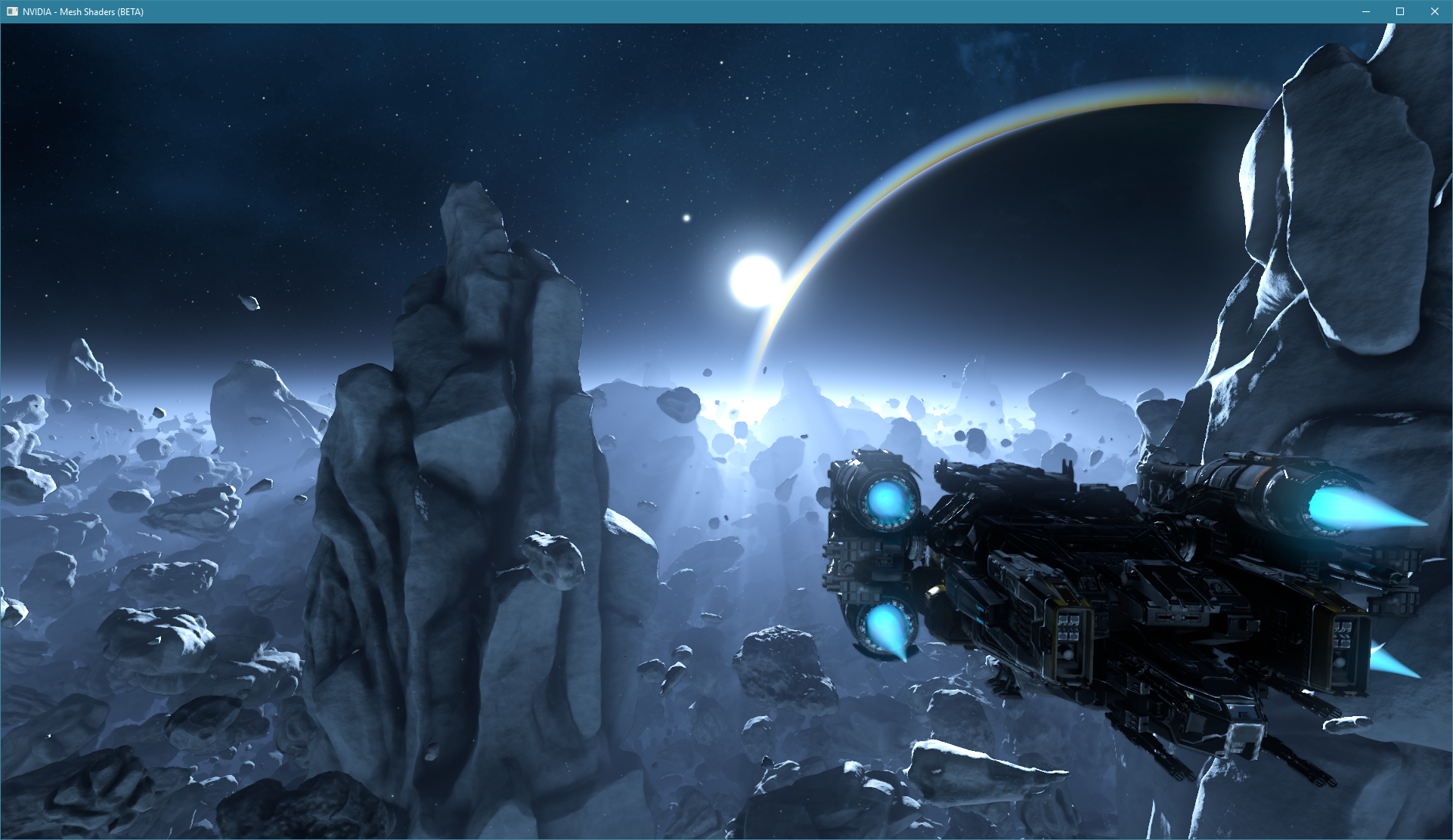
The real world is a visually rich, geometrically complex place. Outdoor scenes in particular can be composed of hundreds of thousands of elements (rocks, trees, small plants, etc.). CAD models present similar challenges with both complex shaped surfaces as well as machinery made of many small parts. In visual effects large structures, for example spaceships, are often detailed with “greebles”. Figure 1 shows several examples where today’s graphics pipeline with vertex, tessellation, and geometry shaders, instancing and multi draw indirect, while very effective, can still be limited when the full resolution geometry reaches hundreds of millions of triangles and hundreds of thousands of objects.
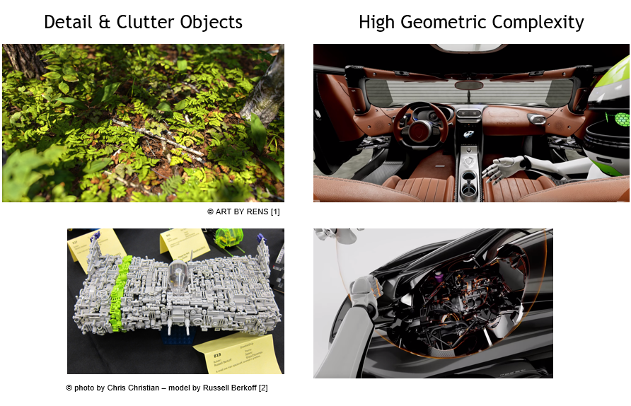
Other use-cases not shown above include geometries found in scientific computing (particles, glyphs, proxy objects, point clouds) or procedural shapes (electric engineering layouts, vfx particles, ribbons and trails, path rendering).
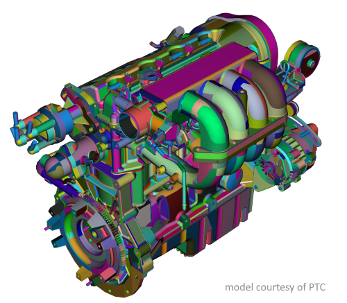
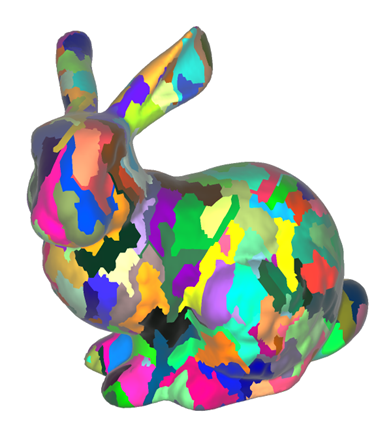
In this post we look at mesh shaders to accelerate rendering of heavy triangle meshes. The original mesh is segmented into smaller meshlets as figure 2 shows. Each meshlet ideally optimizes the vertex re-use within it. Using the new hardware stages and this segmentation scheme, we can render more geometry in parallel while fetching less overall data.
 |
 |
For example CAD data can reach tens to hundreds of millions of triangles. Even after occlusion culling a significant amount of triangles can exist. Some fixed-function steps in the pipeline may do wasteful work and memory loads in this scenario:
- Vertex batch creation by the hardware’s primitive distributor scanning the indexbuffer each time even if the topolgy doesn’t change
- Vertex and attribute fetch for data that is not visible (backface, frustum, or sub-pixel culling)
The mesh shader gives developers new possibilities to avoid such bottlenecks. The new approach allows the memory to be read once and kept on-chip as opposed to previous approaches, such as compute shader-based primitive culling (see [3],[4],[5]), where index buffers of visible triangles are computed and drawn indirectly.
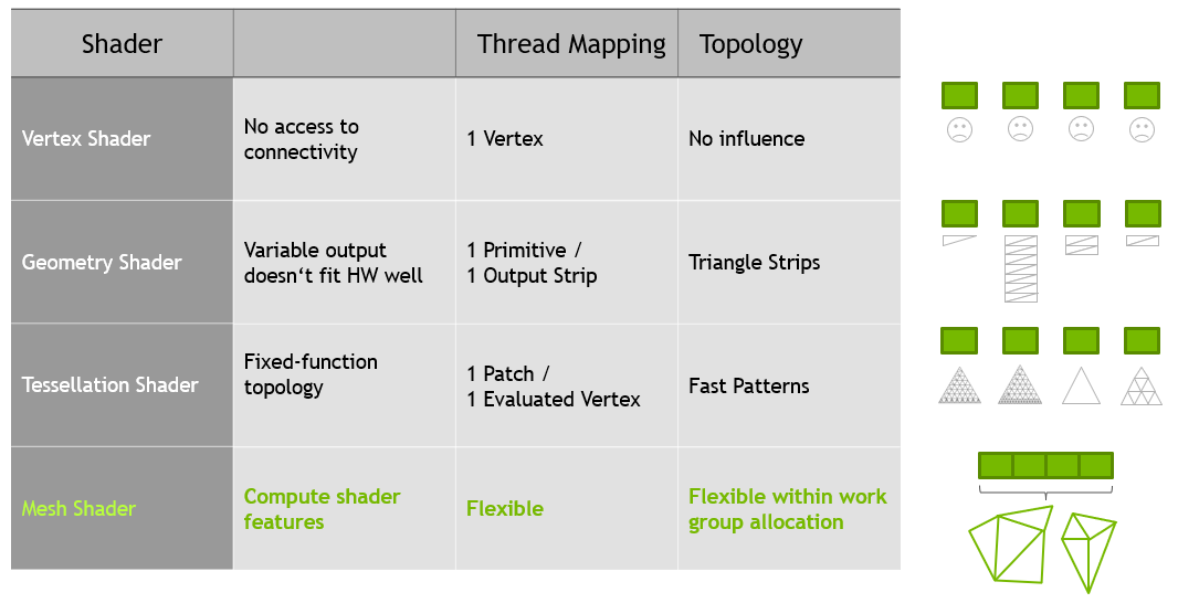
The mesh shader stage produces triangles for the rasterizer, but uses a cooperative thread model internally instead of using a single-thread program model, similar to compute shaders. Ahead of the mesh shader in the pipeline is the task shader. The task shader operates similarly to the control stage of tessellation, in that it is able to dynamically generate work. However, like the mesh shader, it uses a cooperative thread model and instead of having to take a patch as input and tessellation decisions as output, its input and output are user defined.
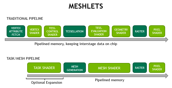
This simplifies on-chip geometry creation compared to the previous rigid and limited tessellation and geometry shaders, where threads had to be used for specific tasks only, as shown in figure 3.
Mesh Shading Pipeline
A new, two-stage pipeline alternative supplements the classic attribute fetch, vertex, tessellation, geometry shader pipeline. This new pipeline consists of a task shader and mesh shader:
- Task shader : a programmable unit that operates in workgroups and allows each to emit (or not) mesh shader workgroups
- Mesh shader : a programmable unit that operates in workgroups and allows each to generate primitives
The mesh shader stage produces triangles for the rasterizer using the above-mentioned cooperative thread model internally. The task shader operates similarly to the hull shader stage of tessellation, in that it is able to dynamically generate work. However, like the mesh shader, the task shader also uses a cooperative thread mode. Its input and output are user defined instead of having to take a patch as input and tessellation decisions as output.
The interfacing with the pixel/fragment shader is unaffected. The traditional pipeline is still available and can provide very good results depending on the use-case. Figure 4 highlights the differences in the pipeline styles.
The new mesh shader pipeline provides a number of benefits for developers:
- Higher scalability through shader units by reducing fixed-function impact in primitive processing. The generic purpose use of modern GPUs helps a greater variety of applications to add more cores and improve shader’s generic memory and arithmetic performance.
- Bandwidth-reduction, as de-duplication of vertices (vertex re-use) can be done upfront, and reused over many frames. The current API model means the index buffers have to be scanned by the hardware every time. Larger meshlets mean higher vertex re-use, also lowering bandwidth requirements. Furthermore developers can come up with their own compression or procedural generation schemes.
The optional expansion/filtering via task shaders allows to skip fetching more data entirely. - Flexibility in defining the mesh topology and creating graphics work. The previous tessellation shaders were limited to fixed tessellation patterns while geometry shaders suffered from an inefficient threading, unfriendly programming model which created triangle strips per-thread.
Mesh shading follows the programming model of compute shaders, giving developers the freedom to use threads for different purposes and share data among them. When rasterization is disabled, the two stages can also be used to do generic compute work with one level of expansion.
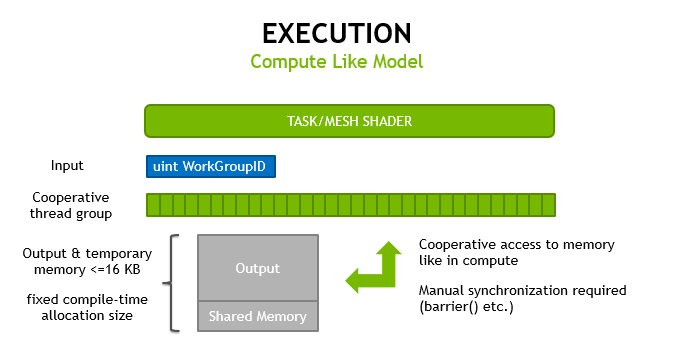
Both mesh and task shaders follow the programming model of compute shaders, using cooperative thread groups to compute their results and having no inputs other than a workgroup index. These execute on the graphics pipeline; therefore the hardware directly manges memory passed between stages and kept on-chip.
We will show an example of how this can be used to do primitive culling, as the threads can access all vertices within a workgroup later. Figure 6 illustrates the ability of task shaders to take care of early culling.
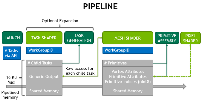
The optional expansion via task shaders allows early culling of a group of primitives or making LOD decisions upfront. The mechanism scales across the GPU and is therefore superseding instancing or multi draw indirect for small meshes. This configuration is similar to the tessellation control shader setting up how much a patch (~task workgroup) is tessellated and then influencing how many tessellation evaluation invocations (~mesh workgroups) are created.
There is a limitation on how many mesh workgroups a single task workgroup can emit. The first generation hardware supports a maximum of 64K children that can be generated per task. There is no limit on the total number of mesh children across all tasks within the same draw call. Likewise if no task shader is used, no limits exist on the amount of mesh workgroups generated by the draw call. Figure 7 illustrates how this works.
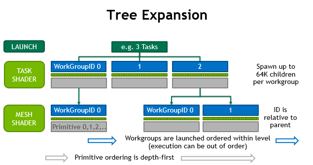
Children of the task T are guaranteed to be launched after children of task T-1. However, task and mesh workgroups are fully pipelined, so that there is no waiting for the completion of previous children or tasks.
The task shader should be used for dynamic work generation or filtering. Static setups benefit from using the mesh shaders alone.
The rasterization output ordering of the meshes and the primitives within them is preserved. With rasterization disabled, both task and mesh shaders can be used to implement basic compute-trees.
Meshlets and Mesh Shading
Each meshlet represents a variable number of vertices and primitives. There are no restrictions regarding the connectivity of these primitives. However, they must stay below a maximum amount, specified within the shader code.
3 * 126 + 4 maximizes the fit into a 3 * 128 = 384 bytes block. Going beyond 126 triangles would allocate the next 128 bytes. 84 and 40 are other maxima that work well for triangles.In each GLSL mesh-shader code, a fixed amount of mesh memory per workgroup is allocated in the graphics pipeline for every workgroup.
Maximums and sizes and primitive output are defined as follows:
The allocation size of each meshlet depends on the compile-time sizing information as well as which output attributes are referenced by the shader. The smaller the allocation, the more workgroups can be executed in parallel on the hardware. As with compute, workgroups share a common section of on-chip memory they can access. Therefore we recommend you be as efficient as possible in the way all outputs or shared memory is used. This is already true for current shaders. However, the memory footprint can be higher since we allow a greater number of vertices and primitives than in the current programming.
// Set the number of threads per workgroup (always one-dimensional).
  // The limitations may be different than in actual compute shaders.
  layout(local_size_x=32) in;

  // the primitive type (points,lines or triangles)
  layout(triangles) out;
  // maximum allocation size for each meshlet
  layout(max_vertices=64, max_primitives=126) out;

  // the actual amount of primitives the workgroup outputs ( <= max_primitives)
  out uint gl_PrimitiveCountNV;
  // an index buffer, using list type indices (strips are not supported here)
  out uint gl_PrimitiveIndicesNV[]; // [max_primitives * 3 for triangles]
Turing supports another new GLSL extension, NV_fragment_shader_barycentric, which enables the fragment shader to fetch the raw data of the three vertices that make a primitive and interpolate it manually. This raw access means we can output “uint” vertex attributes, but use the various pack/unpack functions to store floats as fp16, unorm8 or snorm8. This can greatly reduce the per-vertex footprint again for normals, texture coordinates, and basic color values and benefits both standard as well as the mesh shading pipeline.
Additional attributes for vertices and primitives are defined as follows:
out gl_MeshPerVertexNV {
     vec4  gl_Position;
     float gl_PointSize;
     float gl_ClipDistance[];
     float gl_CullDistance[];
  } gl_MeshVerticesNV[];            // [max_vertices]

  // define your own vertex output blocks as usual
  out Interpolant {
    vec2 uv;
  } OUT[];                          // [max_vertices]

  // special purpose per-primitive outputs
  perprimitiveNV out gl_MeshPerPrimitiveNV {
    int gl_PrimitiveID;
    int gl_Layer;
    int gl_ViewportIndex;
    int gl_ViewportMask[];          // [1]
  } gl_MeshPrimitivesNV[];          // [max_primitives]
One goal is to have the smallest number of meshlets, therefore maximizing vertex re-use within the meshlets, and hence wasting fewer allocations. It can be beneficial to apply a vertex cache optimizer on the indexbuffer prior to the generation of the meshlet data. For example, Tom Forsyth’s linear-speed optimizer can be used for this. Optimizing the vertex locations along with the index buffer is also beneficial, as the ordering of original triangles will be preserved when using the mesh shaders. CAD models often are often “naturally” generated with strips and therefore can already have good data locality. Changing the indexbuffers can have negative side effects on the cluster culling properties of a meshlet for such data (see task-level culling).
Pre-Computed Meshlets
As an example, we render static content where the index buffers are not changing for many frames. Therefore the cost of generating the meshlet data can be hidden during upload of vertices/indices to device memory. Additional benefits can be achieved when the vertex data is also static (no per-vertex animation; no changes in vertex positions), allowing precomputing data useful for quickly culling entire meshlets.
Data Structures
In future samples we will provide a meshlet builder that contains a basic implementation that scans the provided indices and creates a new meshlet every time either of the the size limitations (vertex or primitive count) are hit.
For an input triangle mesh it generates the following data:
struct MeshletDesc {
    uint32_t vertexCount; // number of vertices used
    uint32_t primCount;   // number of primitives (triangles) used
    uint32_t vertexBegin; // offset into vertexIndices
    uint32_t primBegin;   // offset into primitiveIndices
  }

  std::vector<meshletdesc>  meshletInfos;
  std::vector<uint8_t>      primitiveIndices;

  // use uint16_t when shorts are sufficient
  std::vector<uint32_t>     vertexIndices;
Why are there two index buffers?
The following original triangle index buffer sequence
// let's look at the first two triangles of a batch of many more triangleIndices = { 4,5,6, 8,4,6, ...}
is split into two new indexbuffers.
We build a set of unique vertex indices as we iterate through the triangle indices. This process is also known as vertex de-duplication.
vertexIndices = { 4,5,6,  8, ...}
// For the second triangle only vertex 8 must be added
// and the other vertices are re-used.
The primitive indices are adjusted relative to the vertexIndices entries.
// original data
triangleIndices  = { 4,5,6,  8,4,6, ...}
// new data
primitiveIndices = { 0,1,2,  3,0,2, ...}
// the primitive indices are local per meshlet
Once the appropriate size limitation is hit (either too many unique vertices, or too many primitives), a new meshlet is started. Subsequent meshlets will then create their own set of unique vertices.
Rendering Resources and Data Flow
During rendering we use the original vertex buffers. However, instead of the original triangle indexbuffer we use three new buffers, shown in figure 8 below:
- Vertex Index Buffer as explained above. Each meshlet references a set of unique vertices. The indices for those vertices are stored in a buffer for all meshlets sequentially.
- Primitive Index Buffer as explained above. Each meshlet represents a varying number of primitives. Every triangle requires three primitive indices which are stored in a single buffer. Note: Extra indices may be added to get four byte alignment after each meshlet.
- Meshlet Desc Buffer. Stores the information of workload and buffer offsets for each meshlet, as well as cluster culling information.
These three buffers are actually smaller than the original index-buffers due to the higher vertex re-use that mesh shading allows. We noticed a reduction to around 75% of the original index-buffer sizes typically occurred.
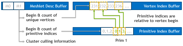
- Meshlet Vertices:
vertexBeginstores the starting location from where we will start fetching vertex indices.vertexCountstores the number of contiguous vertices involved. The vertices are unique within a meshlet; there are no duplicate index values. - Meshlet Primitives:
primBeginstores the starting location for the primitive indices from where we will start fetching indices.primCountstores the amount of primitives involved in the meshlet. Note that the number of indices depends on the primitive type (here: 3 for triangles). It is important to notice that the indices are referencing vertices relative tovertexBegin, meaning that index ‘0’ would refer to the vertex index located atvertexBegin.
The following pseudo code describes what each mesh shader workgroup performs in principle. It is serial only for illustration purposes.
// This code is just a serial pseudo code,
  // and doesn't reflect actual GLSL code that would
  // leverage the workgroup's local thread invocations.

  for (int v = 0; v < meshlet.vertexCount; v++){
    int vertexIndex = texelFetch(vertexIndexBuffer, meshlet.vertexBegin + v).x;
    vec4 vertex = texelFetch(vertexBuffer, vertexIndex);
    gl_MeshVerticesNV[v].gl_Position = transform * vertex;
  }

  for (int p = 0; p < meshlet.primCount; p++){
    uvec3 triangle = getTriIndices(primitiveIndexBuffer, meshlet.primBegin + p);
    gl_PrimitiveIndicesNV[p * 3 + 0] = triangle.x;
    gl_PrimitiveIndicesNV[p * 3 + 1] = triangle.y;
    gl_PrimitiveIndicesNV[p * 3 + 2] = triangle.z;
  }

  // one thread writes the output primitives
  gl_PrimitiveCountNV = meshlet.primCount;
The mesh shader could look something like this when written in parallel fashion:
void main() {
  ...

  // As the workgoupSize may be less than the max_vertices/max_primitives
  // we still require an outer loop. Given their static nature
  // they should be unrolled by the compiler in the end.

  // Resolved at compile time
  const uint vertexLoops =
    (MAX_VERTEX_COUNT + GROUP_SIZE - 1) / GROUP_SIZE;

  for (uint loop = 0; loop < vertexLoops; loop++){
    // distribute execution across threads
    uint v = gl_LocalInvocationID.x + loop * GROUP_SIZE;

    // Avoid branching to get pipelined memory loads.
    // Downside is we may redundantly compute the last
    // vertex several times
    v = min(v, meshlet.vertexCount-1);
    {
      int vertexIndex = texelFetch( vertexIndexBuffer,
                                    int(meshlet.vertexBegin + v)).x;
      vec4 vertex = texelFetch(vertexBuffer, vertexIndex);
      gl_MeshVerticesNV[v].gl_Position = transform * vertex;
    }
  }

  // Let's pack 8 indices into RG32 bit texture
  uint primreadBegin = meshlet.primBegin / 8;
  uint primreadIndex = meshlet.primCount * 3 - 1;
  uint primreadMax   = primreadIndex / 8;

  // resolved at compile time and typically just 1
  const uint primreadLoops =
    (MAX_PRIMITIVE_COUNT * 3 + GROUP_SIZE * 8 - 1)
      / (GROUP_SIZE * 8);

  for (uint loop = 0; loop < primreadLoops; loop++){
    uint p = gl_LocalInvocationID.x + loop * GROUP_SIZE;
    p = min(p, primreadMax);

    uvec2 topology = texelFetch(primitiveIndexBuffer,
                                int(primreadBegin + p)).rg;

    // use a built-in function, we took special care before when
    // sizing the meshlets to ensure we don't exceed the
    // gl_PrimitiveIndicesNV array here

    writePackedPrimitiveIndices4x8NV(p * 8 + 0, topology.x);
    writePackedPrimitiveIndices4x8NV(p * 8 + 4, topology.y);
  }

  if (gl_LocalInvocationID.x == 0) {
    gl_PrimitiveCountNV = meshlet.primCount;
  }
This example is just a straight-forward implementation. Due to all data fetching being done by the developer, custom encodings, decompression via subgroup intrinsics or shared memory, or temporarly using the vertex outputs are possible to save additional bandwidth.
Cluster Culling with Task Shader
We try to squeeze more information into a meshlet descriptor to perform early culling. We have experimented with using 128-bit descriptors that encode the previous mentioned values, as well as relative bbox and a cone for backface-cluster culling as presented by G.Wihlidal. When generating meshlets, one needs to balance good cluster-culling properties with improved vertex re-use. One may influence the other negatively.
The task shader below culls up to 32 meshlets.
layout(local_size_x=32) in;

taskNV out Task {
  uint      baseID;
  uint8_t   subIDs[GROUP_SIZE];
} OUT;

void main() {
  // we padded the buffer to ensure we don't access it out of bounds
  uvec4 desc = meshletDescs[gl_GlobalInvocationID.x];

  // implement some early culling function
  bool render = gl_GlobalInvocationID.x < meshletCount && !earlyCull(desc);

  uvec4 vote  = subgroupBallot(render);
  uint  tasks = subgroupBallotBitCount(vote);

  if (gl_LocalInvocationID.x == 0) {
    // write the number of surviving meshlets, i.e.
    // mesh workgroups to spawn
    gl_TaskCountNV = tasks;

    // where the meshletIDs started from for this task workgroup
    OUT.baseID = gl_WorkGroupID.x * GROUP_SIZE;
  }

  {
    // write which children survived into a compact array
    uint idxOffset = subgroupBallotExclusiveBitCount(vote);
    if (render) {
      OUT.subIDs[idxOffset] = uint8_t(gl_LocalInvocationID.x);
    }
  }
}
The corresponding mesh shader now uses the information form the task shader to identify which meshlet to generate.
taskNV in Task {
  uint      baseID;
  uint8_t   subIDs[GROUP_SIZE];
} IN;

void main() {
  // We can no longer use gl_WorkGroupID.x directly
  // as it now encodes which child this workgroup is.
  uint meshletID = IN.baseID + IN.subIDs[gl_WorkGroupID.x];
  uvec4 desc = meshletDescs[meshletID];
  ...
}
We only culled the meshlets in the task shader in the context of rendering large triangle models. Other scenarios may involve picking different meshlet data later on depending on level-of-detail decision making, or completely generating the geometry (particles, ribbons etc.). Figure 9 below is from a demo that uses task shaders for level-of-detail computation.
Conclusion
Some of the key takeaways:
- A triangle mesh can be converted into meshlets by scanning the index buffer once. Vertex cache optimizers that help classic rendering also help improve meshlet packing efficiency. More sophisticated clustering allows improved early rejection in the task shader stage (tighter bounding boxes, coherent triangle normals etc.).
- The task shader allows skipping of a group of primitives early, before the hardware needs to allocate vertex/primitive memory for a mesh shader invocation on-chip. It also enables generating more than one child invocation if necessary.
- Vertices are processed in parallel across the workgroup’s threads, just like the original vertex shaders.
- Vertex shaders can be made mostly compatible with mesh shaders with a few preprocessor insertions.
- Less data needs to be fetched due to greater vertex re-use (classic vertex shaders operate with a limit of max_vertices = 32 and max_primitives = 32). Average triangle mesh valences suggest that using twice the amount of triangles as vertices is beneficial.
- All data loads are handled via shader instructions instead of the classic fixed function primitive fetch and therefore scales better with more Streaming Multiprocessors. It also allows easier use of custom vertex encodings to further reduce bandwidth.
- For heavy use of vertex attributes, a primitive culling phase that also operates in parallel may be beneficial. This allows us to skip loading vertex data for primitives that would be culled away. However, the best gains are made by efficient culling at the task-level.
You can find more information on the Turing architecture here. Please add your thoughts in the comments section, below. Sample code and driver support will soon be available. If you’re an NVIDIA developer working with Turing advanced shaders, check out the the game developer forums, where you can interact with a community of NVIDIA developers.
References
- [1]: Art by Rens
- [2]: photo by Chris Christian – model by Russell Berkoff
- [3]: Optimizing Graphics Pipeline with Compute – Graham Wihlidal
- [4]: GPU-Driven Rendering Pipelines – Ulrich Haar & Sebastian Aaltonen
- [5]: The filtered and culled Visibility Buffer – Wolfgang Engel
Appendix: SIGGRAPH Presentation
Here is the full SIGGRAPH presentation upon which this blog post builds, for your viewing pleasure.