Jetson Nano 2GB Developer Kit User Guide
Introduction
The NVIDIA® Jetson Nano™ 2GB Developer Kit
is ideal for teaching, learning, and developing AI and robotics. With an active developer community and ready-to-build open-source projects, you’ll find all the resources you need to get started. It delivers incredible AI performance at a low price and makes the world of AI and robotics accessible to everyone with the exact same NVIDIA software and tools used to create breakthrough AI products across all industries.
A Jetson Nano 2GB Developer Kit includes a non-production specification Jetson module (P3448-0003) attached to a reference carrier board (P3542-0000). This user guide covers two revisions of the developer kit:
- Part Number 945-13541-0000-000 including 802.11ac wireless adapter and cable
- Part Number 945-13541-0001-000 NOT including adapter and cable
Jetson Nano 2GB Developer Kit is supported by the comprehensive NVIDIA® JetPack™ SDK, and has the performance and capabilities needed to run modern AI workloads. JetPack includes:
- Desktop Linux with NVIDIA drivers
- AI and Computer Vision libraries and APIs
- Support for cloud-native technologies such as containerization and orchestration
- Developer tools, documentation, and sample code
Included in the box
- Non-production specification Jetson module and reference carrier board
- Paper booklet with Quick Start and support information
-
802.11ac wireless adapter with extension cable*
* The 802.11ac wireless adapter isn’t initially available in all regions. In those locations, 945-13541-0001-000 without the adapter and cable will be sold until 945-13541-0000-000 becomes available.
Overview of the Developer Kit


Precautions - read before operating
- The developer kit may become hot during use. Do not touch heatsink during or right after use
- USB Type A ports are not meant for charging other devices
- The developer kit should not be set on a conductive surface. Pins on the underside of the carrier board will short, damaging the developer kit
- The microSD Card slot has push - push mechanism. Push the first time to lock card in. Push again to release the card and remove it.

Developer Kit Setup
Before using your developer kit, you need to set up a microSD card with the operating system and JetPack components. The simplest method is to download the microSD card image and follow instructions found in Getting Started with Jetson Nano 2GB Developer Kit .
You'll need to supply the microSD Card (UHS-1 32GB minimum) and a USB-C power supply (5V⎓3A).
microSD Card lifespan is a consideration when using a swap file. High endurance and/or larger capacity microSD Cards are recommended
Setup via SD Card Image (Recommended)
The recommended way to setup your developer kit involves downloading a system image and writing it to your microSD Card. Simply follow the instructions available in the Getting Started Guide
Setup via NVIDIA SDK Manager
NVIDIA SDK Manager is a graphical tool for use on a Linux host computer (running Ubuntu 18.04 or Ubuntu 16.04). It provides a menu based method for installing JetPack on a Jetson developer kit. Using this tool is a more involved way of setting up your Jetson developer kit, but it allows you to also install JetPack components on the host computer for cross compilation purposes. To get started quickly with your developer kit, we recommend the SD card image method linked above.
If you want to use SDK Manager, please refer to the SDK Manager documentation .
Headless Operation
Headless mode is handy when you don’t have a display around (or for some special purposes). After setting up in headless mode, you can use the developer kit either via network connection or simply by connecting it to another computer with a Micro USB cable.
If no display is attached to the developer kit during first boot, the initial configuration process will be headless. You will need to complete initial setup via serial application (e.g., puTTY) on another computer connected to the developer kit’s Micro-USB port.
Refer to instructions here for headless mode setup.
Carrier Board Layout

[DS1] Power LED; lights when the developer kit is powered on
[J1] SO-DIMM connector for Jetson module. Module is pre-assembled on the developer kit
[J2] USB Type C power connector for 5V⎓3A power supply. See power section
[J3] RJ45 ethernet connector. See networking section
[J4] HDMI connector
[J5] Camera connector for MIPI-CSI2 camera. See camera section
[J6] 40-pin header : Includes power pins ( +5V/+3.3V) and interface signal pins for I2C (2x), UART, SPI (2x), I2S, and GPIOs
[J7] 4-pin fan control header . Pulse Width Modulation (PWM) output and tachometer input are supported
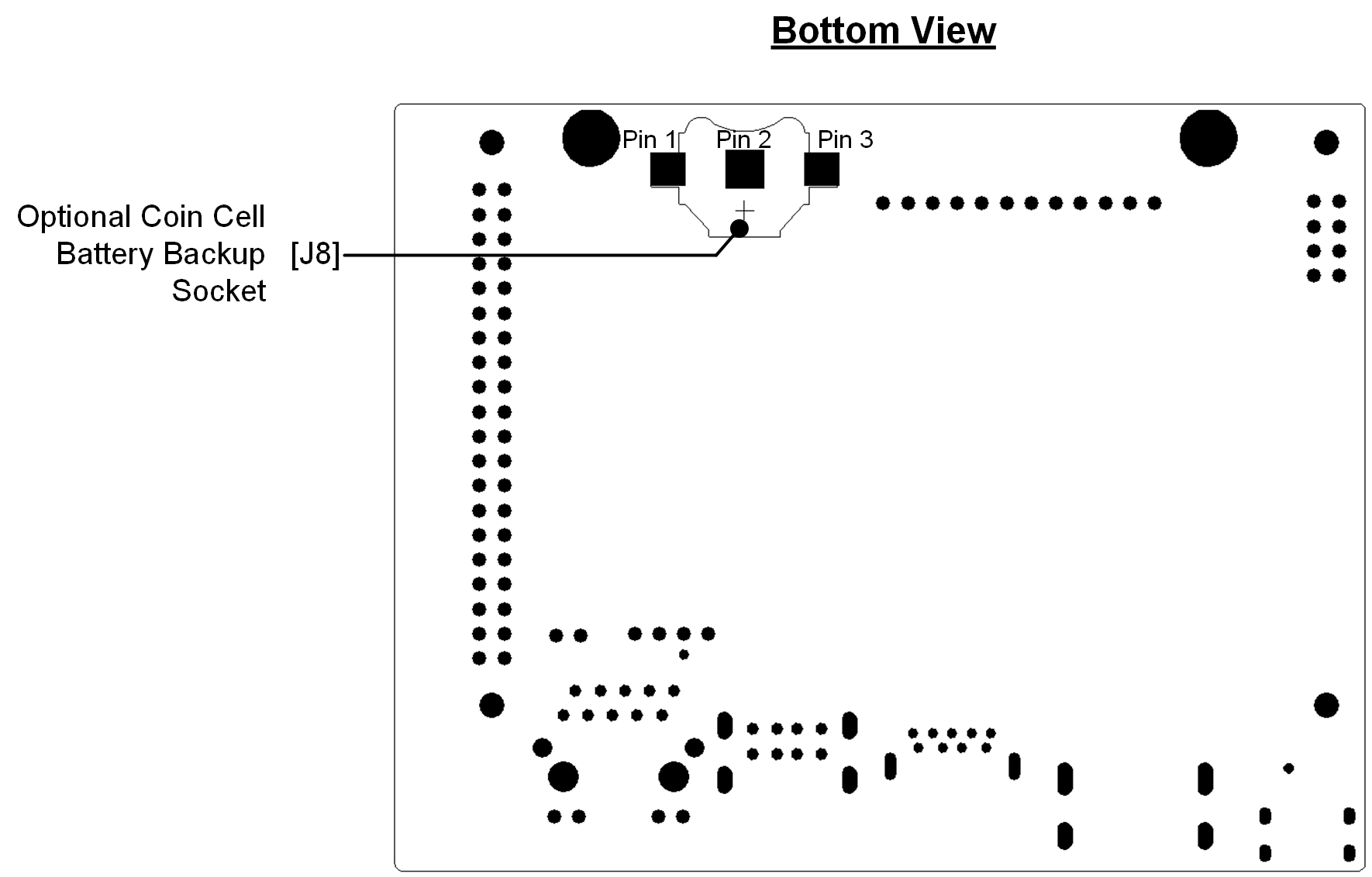
[J8] Optional coin-cell socket
[J9] USB 3.0 type A connector. Limited to 1A total power delivery
[J10] Stack of two USB 2.0 type A connectors supporting Host Mode only
[J11] Optional button header (2x4); Includes connections for Reset/Force Recovery/Power Buttons, and Auto-power-on disable
[J12] Button header (1x12); Includes connections for power LED, Reset/Force Recovery/Power Buttons, UART, and Auto-power-on disable
[J13] Micro-USB 2.0 connector supporting Recovery Mode and Device Mode
40-Pin Header (J6)
The 40-pin header provides access to power, ground, and interface signal pins.
-
Power pins
-
There are two 3.3V power pins and two 5V power pins. These are not switchable; power is always available when the developer kit is connected to power.
- The two 5V pins can be used to power the developer kit at 2.5A each. (Do not power the developer kit via these pins and USB-C connector at the same time.)
-
-
Interface signal pins
- All signals use 3.3V levels
-
By default, all interface signal pins are configured as GPIOs, except those supporting I2C and UART
Jetson.GPIO offers an easy way to control GPIO pins. Jetson-IO can be used to reconfigure pin functions, e.g., from GPIO to SFIO (Special Function I/O) such as I2C, I2S, etc . Both Jetson.GPIO and Jetson-IO are already included in JetPack.
Note that the I2C interface pins are pulled up with 2.2kohm resistors to 3.3V. All signals except the I2C interfaces connect to the SoC through Texas Instruments TXB0108RGYR level shifters. See " Jetson Nano Developer Kit 40-Pin Expansion Header GPIO Usage Considerations " for more information on these level shifters and how to work with signals that connect to them.

12-Pin Button Header (J12)
This header provides GPIO to control the state of the board. Enclosures for the developer kit can connect to this header.

| Pin | Name | Description | Power |
|---|---|---|---|
| 1 | Power LED - | Connects to LED Cathode to indicate System Sleep/Wake (Off when system in sleep mode) | +5V |
| 2 | Power LED + | Connects to LED Anode (see pin 1) | +5V |
| 3 | UART2_RXD | Receive | +3.3V |
| 4 | UART2_TXD | Transmit | +3.3V |
| 5 | Latch Set | Connect pin 5 and pin 6 to disable Auto-Power-On and require power button press (or equivalent) | +5V |
| 6 | Latch Set Button | Connect pin 5 and pin 6 to disable Auto-Power-On and require power button press (or equivalent) | +5V |
| 7 | Ground |
|
|
| 8 | Reset Button | Connect normally open button to pin 7 and pin 8. Temporarily press button to initiate system reset | +1.8V |
| 9 | Ground |
|
|
| 10 | Recovery Mode Button | Connect normally open button to pin 9 and pin 10. Hold button down while powering on the system to put it in USB Force Recovery mode | +1.8V |
| 11 | Ground |
|
|
| 12 | Power Button | Connect normally open button to pin 11 and pin 12. Temporarily press button to initiate power-on if Auto-Power-On disabled (pin 5 and pin 6 connected) | +5V |
8-Pin Button Header (J11)
This is an alternate 8-Pin (2x4) button header that can be soldered on the carrier board in location J11 and used in alternative of the main button header.
Header details ( examples ):
- Total pins/positions 8
- 2 rows of 4 pins
- Pitch is 2.54mm
- Unshrouded
- Through hole vertical

| Pin | Name | Description | Power |
|---|---|---|---|
| 1 | Power Button | Connect normally open button to pin 1 and pin 2. Temporarily press button to initiate power-on if Auto-Power-On disabled (pin 7 and pin 8 connected) | +5V |
| 2 | Ground |
|
|
| 3 | Force Recovery Button | Connect normally open button to pin 3 and pin 4. Hold button down while powering on the system to put it in USB Force Recovery mode | +1.8V |
| 4 | Ground |
|
|
| 5 | Reset Button | Connect normally open button to pin 5 and pin 6. Temporarily press button to initiate system reset | +1.8V |
| 6 | Ground |
|
|
| 7 | Latch Set Button | Connect pin 7 and pin 8 to disable Auto-Power-On and require power button press (or equivalent) | +5V |
| 8 | Latch Set | Connect pin 7 and pin 8 to disable Auto-Power-On and require power button press (or equivalent) | +5V |
4-Pin Fan Header (J7)
The pinout of the 4-pin fan control header at location J7 is shown below.
Initial units of the Jetson Nano 2GB Developer Kit without wireless networking adapter (PN: 945-13541-0001-000) do not have a fan header already stuffed at J7. See fan header installation below if you have a developer kit without fan header and you want to install one.
The header can support either a 3-pin fan connection (GND, PWR, and TACH) or a 4-pin fan connection (GND, PWR, TACH, and PWM). Using a fan with PWM capability allows software to adjust the speed of the fan as needed. Only 5V fans are supported.

| Pin | Description |
|---|---|
| 1 | Ground |
| 2 | +5V Power |
| 3 | Tachometer |
| 4 | PWM (Pulse Width Modulation) |
Controlling the fan
Fan can be controlled through PWM.
Check the L4T fan control documentation
If you want to add a fan to the system, please select a 5V fan that:
- Uses a standard ATX fan connector
- Follows the ATX fan pinout
- Has 40mm x 40mm screw spacing for connection with the developer kit heatsink
Fan Header Installation
If you have a developer kit without fan connector, you can solder a suitable connector to the carrier board as shown below. Select a keyed connector that will work with either 3-pin or a 4-pin fans. S ee this example fan connector search .
The figure on the left shows where the connector is to be installed. Be sure to install with pin 1 in the correct place as shown. As example, the figure on the right shows a fan header installed in a Jetson Nano Developer Kit carrier board.

We recommend precaution in soldering the fan connector in J7 in order to avoid damages to other components. NVIDIA will continue to provide warranty for the entire product as-is for clean solders on the J7 fan connector.
During the soldering process the PCB silkscreen may suffer cosmetic scratches. That is normal and will not affect the board function. In that case, Customer shall continue to use the functioning board and NVIDIA may reject RMA requests for cosmetic reasons.
Power
The developer kit supports USB-C power supplies of 5V ± 5%, 3A. If your phone uses a USB-C power supply, there is a chance that it is enough to power the devkit. Check its specifications.
For a list of validated power supplies, consult our Supported Components List .
If the voltage drops below 4.25V, the system will shut down.
The Jetson Nano 2GB Developer Kit cannot be powered via the Micro-USB connector.
Power Consumption
The developer kit’s total power usage is the sum of carrier board, module, and peripheral power usage, as determined by your particular use case.
There are two software-defined power modes for the Jetson module. The power mode can be switched with the UI interface at the top right of the desktop, or by following the L4T power management guide.
The two module power modes are:
- 10W - default mode for more performance
- 5W - suggested for less energy use
See the L4T power management guide for more details and instructions about how to create your own power mode.
Power via 40-pin Header
The developer kit can be powered by connecting the 40-pin header's 5V pins to an external power supply, Each of the two pins will support 2.5A.
Do not power the developer kit via 40-pin header pins and USB-C connector at the same time.
Battery Powered Operation
For applications which require the developer kit to be run on a battery (like JetBot), we suggest using a USB-C power bank.
Be sure to use a battery which can sustain voltage above 4.25V, else the system will shut down.
Networking
The developer kit supports wired and wireless networking:
- Wired - Ethernet will be available as soon as a cable with network connection is plugged into the RJ45 port
- WLAN - Wireless networks will be available after plugging in a supported USB wireless networking adapter
- WPAN - Bluetooth will be available after plugging in a supported USB Bluetooth adapter
Available networks can be discovered through the networking icon at the top right corner of the desktop or via System Settings. To change any default networking configurations please use the Settings page.
Any wireless networking or Bluetooth adapter should be connected to the USB 3.0 port (the single USB port that is not stacked) for better performance. An extension cable is suggested in order to reduce EMI interference between USB networking adapter and the developer kit.
Ethernet Port LED Behavior
The Ethernet port has two LEDs:
- Green LED : is on if a GigabitEethernet connection is active. The LED is off if no Ethernet connection is active, or if a connection with speeds lower than 1 gigabit per second is active
-
Amber LED
: flickers if there is traffic flowing through the port
Enabling Bluetooth Audio
See the Connecting Bluetooth Audio guide.
Camera
For a full list of cameras supported by the Jetson Ecosystem, visit our
Partner Supported Camera Page
.
All MIPI CSI-2 cameras compatible with Jetson Nano Developer Kit and Jetson Xavier NX Developer Kit will also work with Jetson Nano 2GB Developer Kit.
| Name | Manufacturer | Link | Comment |
|---|---|---|---|
| Raspberry Pi Camera Module V2 | Raspberry Pi | Adafruit |
|
| Raspberry Pi Camera Module NoIR V2 | Raspberry Pi |
|
|
| Raspberry Pi High Quality Camera | Raspberry Pi |
Only on Jetson Nano 2GB Developer Kit.
Download the driver from the download center and follow the instructions included in the package |
Installing a Camera Module
To install a camera module, connect its flex ribbon cable into the camera connector (J5). Follow these steps:
- Gently lift up the the connector latch (see 1st figure).
- Insert the camera ribbon cable. (See 2nd & 3rd figures) The metal contacts should face toward the center of the developer kit.
-
Gently press down on the connector latch until stops. This may require two fingers, each at one end of the latch. Do not use excessive force.


Verifying camera installation
In order to check that the camera is working, check out the Taking Your First Picture Guide .
More info and commands for camera control can be found in the
L4T Guide
under the Multimedia section.
Supported Component List
This Supported Component List provides a list of third party components that NVIDIA has qualified to work with Jetson Nano 2GB Developer Kit.
If a particular component is not listed, it indicates that there are no current plans to validate that component at NVIDIA - it does not imply that the component will not work.
Power Supplies
| Name | Manufacturer | Link | Comment |
|---|---|---|---|
| Raspberry Pi 4 Power Supply USB-C 5.1V 3A | Raspberry |
|
|
| LABISTS Raspberry Pi 4 Power Supply USB-C Charger Adapter with On/Off Switch 5.1V 3A | LABISTS | Amazon (US) |
|
|
CanaKit 3.5A Raspberry Pi 4 Power Supply (USB-C) |
CanaKit | Amazon (US) |
|
Wireless Networking USB Adapters
| Name | Manufacturer | Link | Comment |
|---|---|---|---|
| Archer T2U Nano | TP-Link | Amazon |
|
| Archer T2U Plus | TP-Link | Amazon |
|
| TL-WN722N | TP-Link | Amazon |
|
| AC 600 | Kootek |
|
|
| WUSB6300 | Linksys |
|
Other
| Name / Description | Manufacturer | Link | Comment |
|---|---|---|---|
| 4-pin 5V PWM fan compatible with developer kit heatsink - AFB0405MA-AFGE | Delta Electronics |
|
|
| 4-pin 5V PWM fan compatible with developer kit heatsink - NF-A4x20 5V PWM | Noctua | Noctua |
|