P3663 Networking
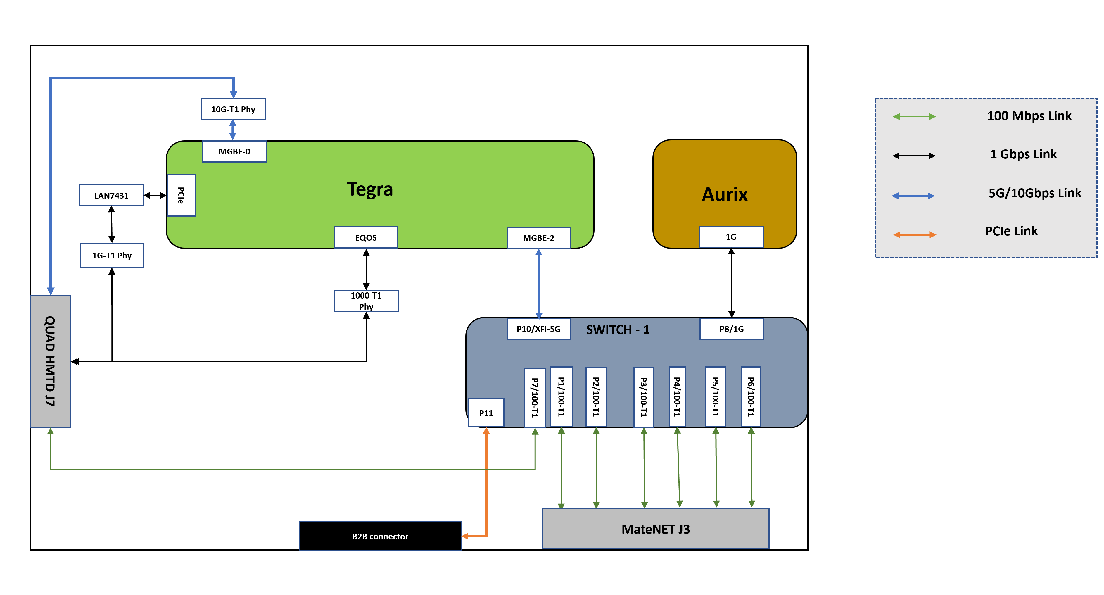
The following diagram shows the P3663 network topology:
External Connector Channels - Mapping to Switch/Controller
QUAD HMTD Connector J7
| Port | Connected to |
|---|---|
| 1 | Switch-1(88Q5072) Port 7 |
| 2 | LAN7431 (PCIe Ethernet Controller) |
| 3 | Tegra MGBE0 Ethernet Controller |
| 4 | Tegra EQOS Ethernet Controller |
MateNET Connector J3
| Port | Pin Number | Connected to |
|---|---|---|
| 1 | Pin 1&2 | Switch (88Q5072) Port 1 |
| 2 | Pin 3&4 | Switch (88Q5072) Port 2 |
| 3 | Pin 5&6 | Switch (88Q5072) Port 3 |
| 4 | Pin 11&12 | Switch (88Q5072) Port 4 |
| 5 | Pin 9&10 | Switch (88Q5072) Port 5 |
| 6 | Pin 7&8 | Switch (88Q5072) Port 6 |
Network Configuration
DRIVE OS 6.0 supports two network configurations named Base and Safety. Base configuration is applicable to standard PCD configuration i.e., AV+L Standard and AV+Q Standard, while Safety is applicable for AV+Q prod, Prod_debug, and prod_debug_extra. These switch configurations are controlled by the AURIX MCU firmware via AURIX command line.
The configuration selection is enabled via AURIX MCU AUTOSAR firmware commands. Commands details:
getnetworkconfig : Get the current network config info
setnetworkconfig <config value>: Sets network config for next MCU boot
Where the <config value> parameter is as below:
| Configuration | Value | Orin PCT (applicable) | Max MTU supported (MGBE2-OAK) | PTP support in OAK Switch | Switch Over the air update support |
|---|---|---|---|---|---|
| NW_CFG_BASE | 0 | AV+L & AV+Q standard | Up to 16Kbytes | Yes (Refer PTP section) | Yes |
| NW_CFG_BASE_SAFETY | 1 | AV+Q Safety | 1500 bytes | Bypass (Switch CPU disable) | No |
The major difference use cases between NW_CFG_BASE and NW_CFG_BASE_SAFETY are:
- Switch CPU & Firmware disabled : In safety platform configurations, Marvell switch CPU (QM) and firmware (ASIL NA) are disabled to achieve DRIVE OS time sync safety goals.
- Max MTU size: In safety platform configurations, The max MTU size in MGBE2 and OAK switch is reduced to ~1500. To minimize the PTP bypass latency time in safety.
- OTA support: In safety, Marvell switch CPU is disabled. Therefore, there is no OTA support for Marvell switches.
Its important keep the software in Orin and network configuration setting in AURIX compatible as defined in the table above. This must be done manually and there is no automated way to keep Orin software and AURIX setnetworkconfig in sync/compatible mode.
Networking Port Configuration
| Node | Controller/Switch Port | Mode & Speed | T1 Role | PHY present | L2 Routing |
|---|---|---|---|---|---|
| Tegra | EQOS | 1G-BASE-T1 | NA | Yes | NA |
| MGBE-0 | 10G-BASE-T1 | Primary | Yes | NA | |
| MGBE-2 | 5G (XFI) | NA | No | NA | |
| Switch-1 (88Q5072) | P0 (Internal CPU port) | 1G | NA | No | No Restriction |
| P1 | 100M-BASE-T1 | Primary | Yes (internal) |
No Restriction except forwarding to Switch-1 P8 |
|
| P2 | 100M-BASE-T1 | Primary | Yes (internal) |
No Restriction except forwarding to Switch-1 P8 |
|
| P3 | 100M-BASE-T1 | Primary | Yes (internal) |
No Restriction except forwarding to Switch-1 P8 |
|
| P4 | 100M-BASE-T1 | Primary | Yes (internal) |
No Restriction except forwarding to Switch-1 P8 |
|
| P5 | 100M-BASE-T1 | Primary | Yes (internal) |
No Restriction except forwarding to Switch-1 P8 |
|
| P6 | 100M-BASE-T1 | Primary | Yes (internal) |
No Restriction except forwarding to Switch-1 P8 |
|
| P7 | 100M-BASE-T1 | Primary | Yes (internal) |
No Restriction except forwarding to Switch-1 P8 |
|
| P8 | 1G (RGMII) | NA | No | Only to P10 | |
| P10 | 5G (XFI) | NA | No | No Restriction | |
| P11 | PCIe Gen3 X1 | NA | No |
No Restriction except forwarding to Switch-1 P8 |
|
| Tegra PCIe Ethernet | LAN 7431 controller | 1G-BASE-T1 | Master | Yes | NA |