Hardware Layout
Developer Kit
Side Views
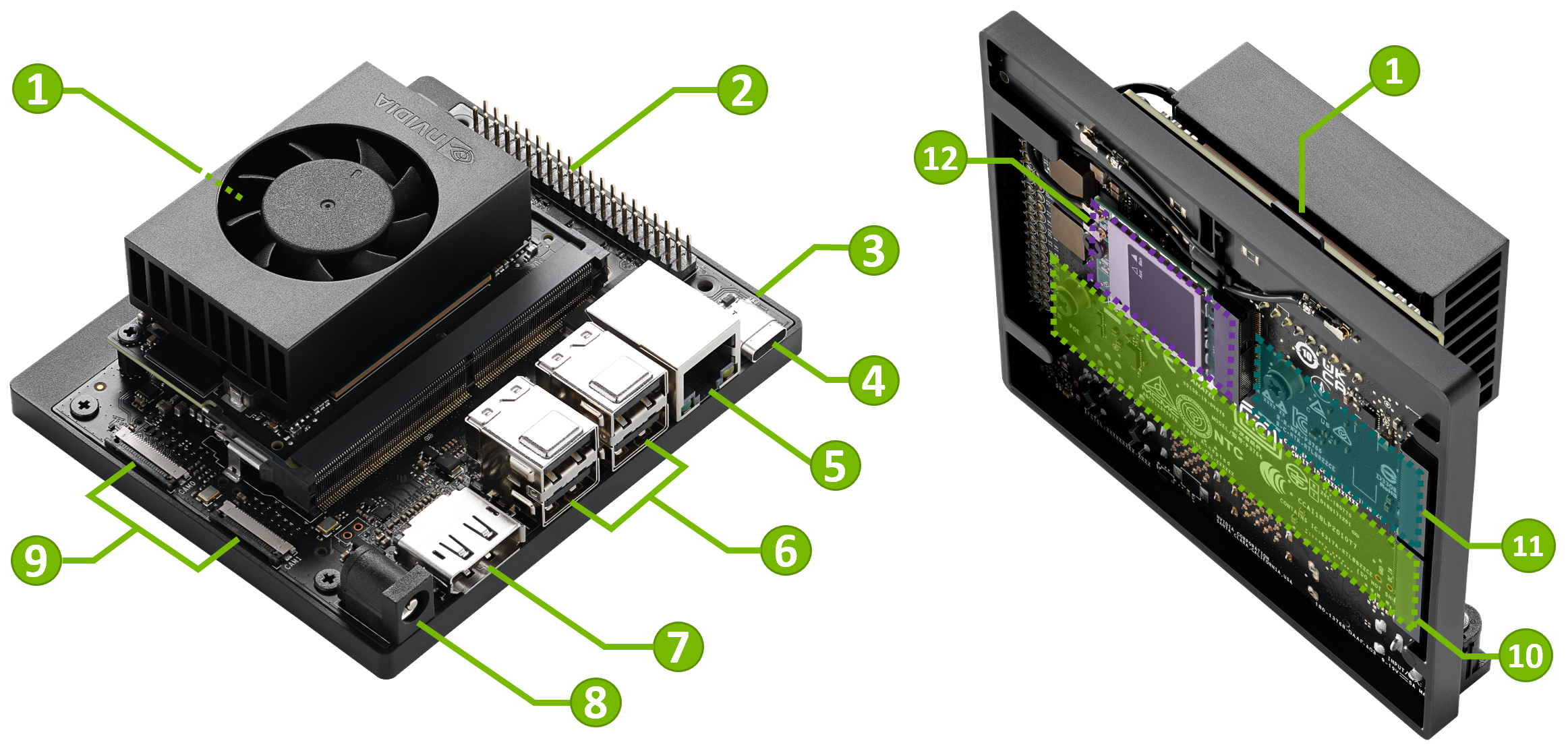
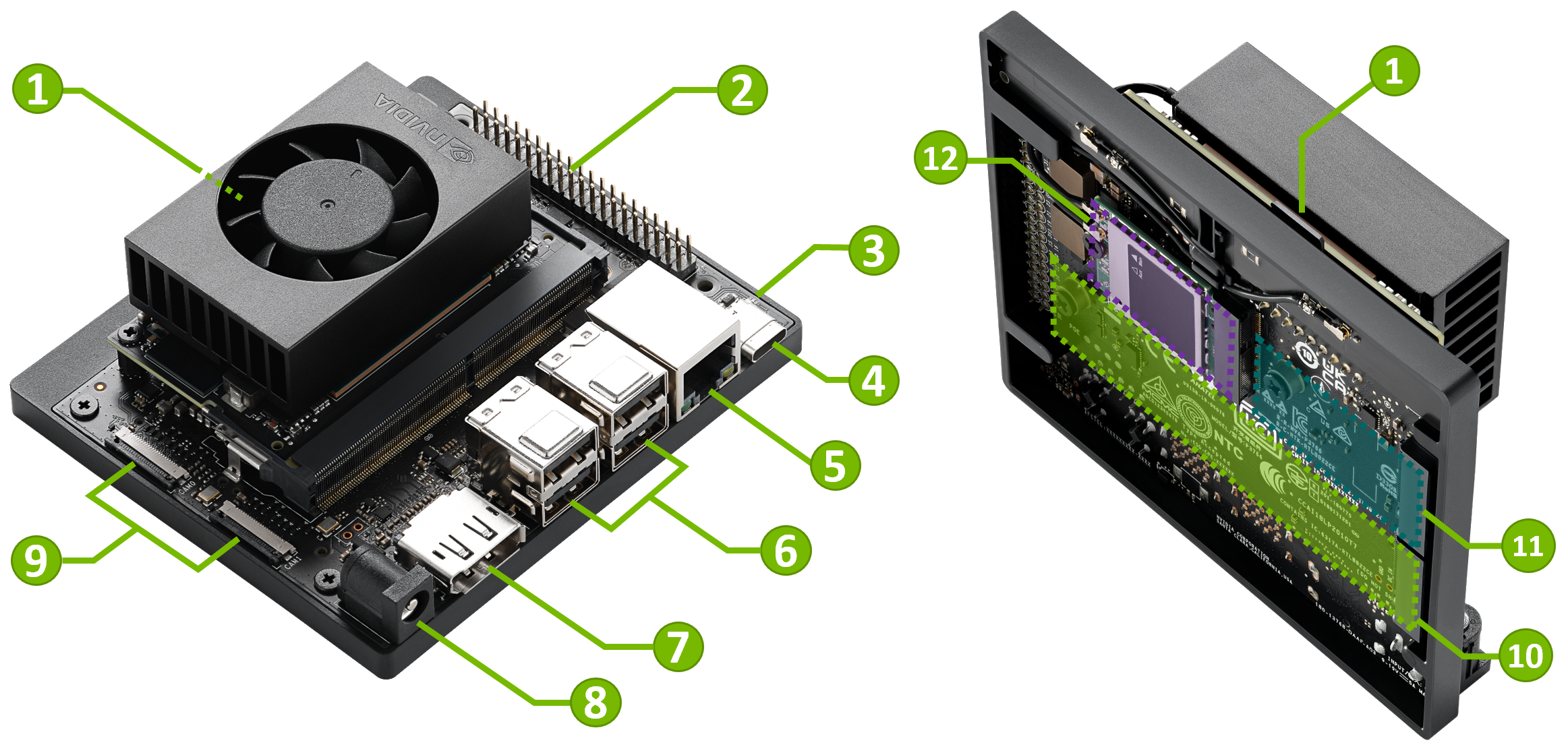
Part Names
| Mark. | Name | Note |
|---|---|---|
| 1 | microSD card slot | |
| 2 | 40-pin Expansion Header | |
| 3 | Power Indicator LED | |
| 4 | USB-C port | For data only |
| 5 | Gigabit Ethernet Port | |
| 6 | USB 3.2 Type-A ports (x4) | 10Gpbs |
| 7 | DisplayPort Output Connector | |
| 8 | DC Power Jack | 5.5mm x 2.5mm |
| 9 | MIPI CSI Camera Connectors (x2) | 22pin, 0.5mm pitch |
| 10 | M.2 Slot (Key-M, Type 2280) | PCIe 3.0 x4 |
| 11 | M.2 Slot (Key-M, Type 2230) | PCIe 3.0 x2 |
| 12 | M.2 Slot (Key-E, Type 2230) | (populated) |
Port and Connector Details
Note
For the detail, see "Jetson Orin Nano Developer Kit Carrier Board Specification" .
Storage
Default storage:
- microSD card on the Jetson Orin Nano module ( 1
)
Optional storage:
- 2280-size NVMe SSD card on M.2 Slot (Key-M, Type 2280) ( 10
)
- 2230-size NVMe SSD card on M.2 Slot (Key-M, Type 2230) ( 11
- USB drive (on any USB port) ( 4 or 6
You can flash the base L4T BSP on to any of the storage medium above using SDK Manager.
See
Step #5 of Use SDK Manager to Flash L4T BSP section on Software Setup with SDK Manager page
USB Ports
USB-C port (
4
)
This USB 3.2 Type-C connector supports Host, Device and USB Recovery mode.
Attention
This USB-C port can NOT be used to output display signal. HDMI or DisplayPort over USB-C are NOT supported.
-
Host mode
You can use this port as a downstream-facing port (DFP), just like the 4 Type-A ports.
You can connect supported USB devices and use Jetson as the host. -
Device mode
You can connect your Jetson to a PC (via USB-C to Type-A cable or USB-C to USB-C cable) and have the Jetson act as a USB device.
USB Device Mode of Jetson expose three logical USB device:
-
USB Mass Storage Device (to let you mount
L4T-READMEdrive) - USB Serial (to provide a serial terminal access)
-
USB Ethernet (RNDIS) device to form a local area network in between your PC and Jetson (your Jetson being
192.168.55.1)
-
USB Mass Storage Device (to let you mount
-
USB Recovery mode
When you put your Jetson into Force Recovery mode, this operates in USB Recovery mode.
You can connect your Jetson to a PC via a USB cable, and use the PC to flash Jetson.
USB 3.2 Type-A ports (
6
)
You can use these Type-A ports to connect USB devices. These are host mode only.
There are two, dual stacked Type-A connectors and each stack VBUS is limited to 3A output current.
DisplayPort Output
To connect a display to the developer kit, use the DisplayPort output port (
8
). This is the only way to get the display out on the developer kit, the NVIDIA Jetson Orin Nano Developer Kit does NOT support HDMI or DisplayPort over USB-C.
To connect to a monitor or TV that only accepts HDMI, you can use an adaptor/cable that converts DisplayPort to HDMI.
DisplayPort output port supports both
passive
and active DisplayPort to HDMI adapters.
40-pin Expansion Header (
2
)
Pin assignment :

For details, see NVIDIA Jetson Orin Nano Developer Kit Carrier Board Specification .
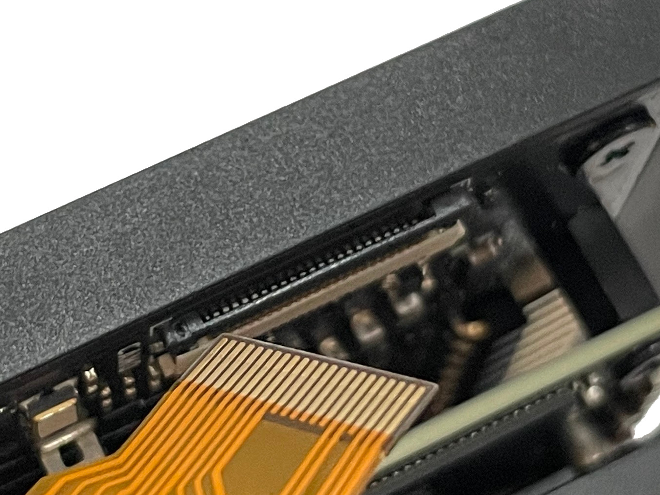
MIPI CSI Camera Connectors (
9
)
Jetson Orin Nano Developer Kit carrier board includes two 22-position flex connectors to connect CSI camera modules.
To connect a CSI camera module with 15-pin connector like Raspberry Pi Camera Module v2, a 15-pin to 22-pin conversion cable is required.
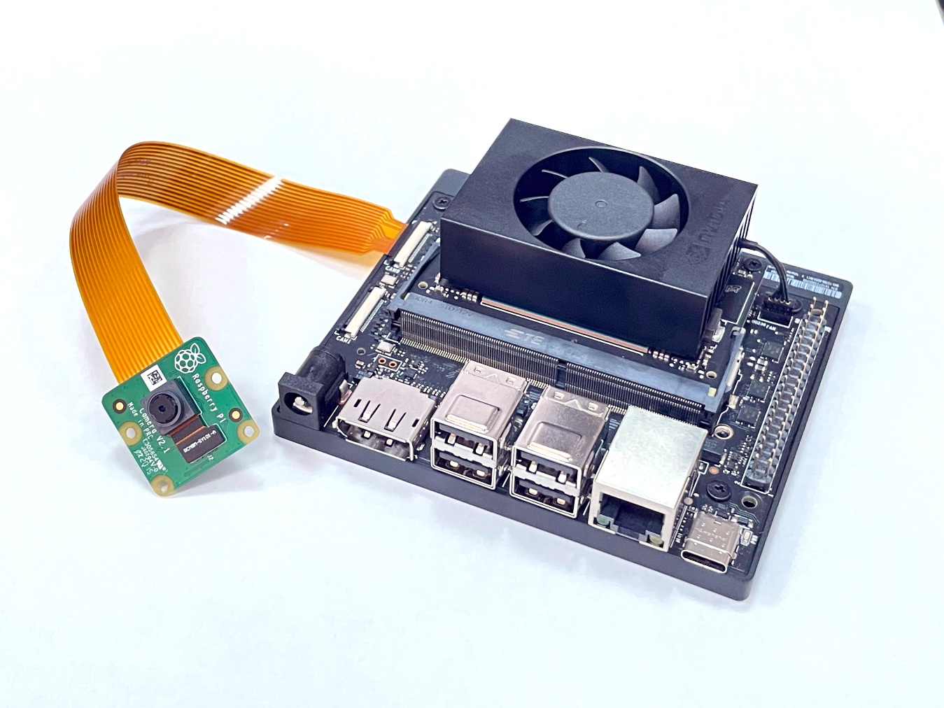
The connectors supports the following.
- CAM0: CSI 1 x2 lane
- CAM1: CSI 1 x2 lane or 1 x4 lane
Those connectors are bottom contact, 0.5mm pitch, 22 position.
For details, see NVIDIA Jetson Orin Nano Developer Kit Carrier Board Specification .