NVIDIA DRIVE AV Storage Configuration#
In the PCT, there are three configuration files that implement the three-level partitioning concept:
global_storage.cfg
This is the root of the definition hierarchy.
It defines the top-level partitioning and contains partitions that are present regardless of which boot chain is active.
It is referred to as the storage configuration file of the first-level (level-1) partition table.
boot_chain_storage.cfg file as mentioned after
sub_cfg_file=in level-1 partitions.Contains partitions that are unique to each of the boot chains.
It is referred to as the storage configuration file of the second-level (level-2) partition table.
linux_gos0_storage.cfg file as mentioned after
sub_cfg_file=in level-2 partitions. - Contains partitions that are unique to each of level-2 extended partitions. - It is referred to as the storage configuration file of the third-level (level-3) partition table.
Multiple UFS LUN Configuration#
By default, DriveOS uses a multiple LUN configuration. In the following configuration, the 256 GB drive is split into two logical LUNs:
238 GB for the main storage device
200 MB for heavy writing logging applications
If you do not want to use the logging LUN, add ENABLE_UFS_LUN1=n to the bind command. For example:
bind_partitions -b p3960-10-sw01 av.linux ENABLE_UFS_LUN1=n
If you do want to use the LUN, ensure your platform has been reprovisioned for two LUNs.
Warning
Provisioning a UFS device wipes all data on it. Please make sure to back up all important data before provisioning.
To provision UFS, you will need a BSP created by flashtools
create_bsp_images.py. This is a one time execution. You do not need to
provision again unless the LUN sizes change or new LUNs are added. For more
information on how to provision the UFS LUNs, please see the section
To Provision a UFS Device through the Flashing Tools.
Steps to follow:
Create the BSP and push to the host where the target is connected.
Set the taget in recovery.
Flash the target with an additional
-Uoption. Pass the absolute path to the provision configuration file, per the following locations: * For PDK:$PDK_TOP/drive-foundation/tools/flashtools/storage_configs/t264/ufs-provision-<size>.cfg* For the BSP image:<bsp_image>/tools/flashtools/storage_configs/t264/ufs-provision-<size>.cfg* You can also create a custom configuration file and provide its path.After successful provisioning, put the board back in recovery.
Flash the target as normal.
Example flash commands for p3960-10-sw01 DRIVE-AGX Thor DevKit (assume bsp_image contains output of create BSP):
cd bsp_imageWithin AURIX:
tegrarecovery x1 onWithin AURIX:
tegrareset x1Provision the board:
./tools/flashtools/bootburn/flash_bsp_images.py -b p3960-10-sw01 -P $PWD/642-63960-0010-000_TS1 -U $PWD/tools/flashtools/storage_configs/t264/ufs-provision-256gb.cfg -D
Within AURIX:
tegrareset x1Flash the board:
./tools/flashtools/bootburn/flash_bsp_images.py -b p3960-10-sw01 -P $PWD/642-63960-0010-000_TS1 -D
The following output should be seen in the flashing kernel after successful provision:
program_lun_debugfs_write: LUN Programming successful
To verify that the board has been provisioned, check for the following in the boot logs:
[ 1.266460] scsi 0:0:0:49488: Well-known LUN MICRON MT256GBCAV4U31AA 0301 PQ: 0 ANSI: 6
[ 1.279496] sd 0:0:0:0: [sda] 62236672 4096-byte logical blocks: (255 GB/237 GiB)ANSI: 6I: 6
[ 1.279502] scsi 0:0:0:1: Direct-Access MICRON MT256GBCAV4U31AA 0301 PQ: 0 ANSI: 6
[ 1.279797] sd 0:0:0:0: [sda] Write Protect is off
[ 1.280109] sd 0:0:0:0: [sda] Write cache: enabled, read cache: enabled, supports DPO and FUA
[ 1.280111] sd 0:0:0:0: [sda] Preferred minimum I/O size 4096 bytes
[ 1.283075] sd 0:0:0:1: [sdb] 51200 4096-byte logical blocks: (210 MB/200 MiB)
[ 1.283251] sd 0:0:0:1: [sdb] Write Protect is off
[ 1.283580] sd 0:0:0:1: [sdb] Write cache: enabled, read cache: enabled, supports DPO and FUA
[ 1.283583] sd 0:0:0:1: [sdb] Preferred minimum I/O size 4096 bytes
If you attempt to flash a board with multiple LUNs that has only been provisioned for a single LUN, the VSC server will show the following error:
Error opening device ufs_lun1
hv_storage: unable to allocate client for ufs_lun1
error setting up post init for virt storage device 4
Programming error:
vsc/hvrtos/virtual_device_manager/vsc_dev_mgr.c:636:"FATAL ERROR: ASSERT"

STACK TRACE:
0x24b30
0x24738
0x239c0
0x42484
Three-Level Partitioning#
The following diagram shows an example of a three-level partition layout and three-level partition tables.
Figure 1. Simplified View of Three-Level Configuration Files 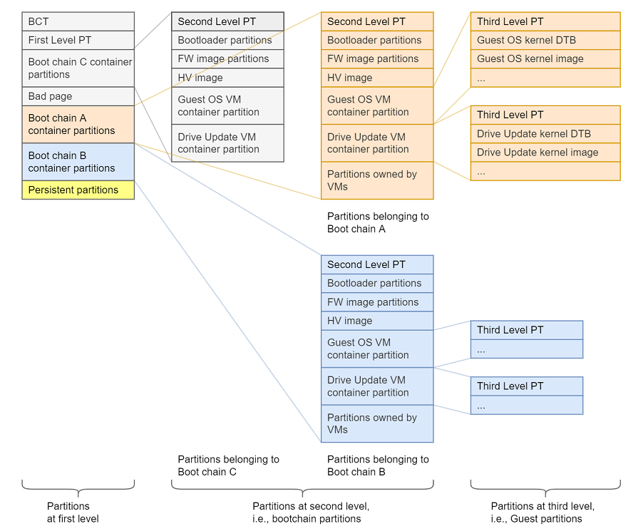
To enable data updates in eMMC and UFS partitions via Over-The-Air(OTA), updates the partitions on eMMC are categorized as follows:
- The eMMC A chain: It consists of all eMMC partitions assigned to all virtual
machines in the Partition Configuration Table (PCT). All content in this chain can be overwritten by the OTA application.
- The eMMC B chain: This is the recovery chain. The target boots in this chain
when the OTA application is about to update other boot chains.
- The QSPI C chain: This is the recovery chain to boot with only QSPI. The
target boots in this chain when the OTA application is about to update other boot chains.
- Persistent partitions for all virtual machines: The data partitions that are
not updated by the OTA application. Data over these partitions remain consistent over multiple OTA cycles.
When inspecting the global_storage.cfg (level-1), you will notice it refers to
boot_chain_storage.cfg as a sub_config file. This elevates the
boot_chain_storage_qspi.cfg to be level-2.
...
[partition]
name=A_qspi_chain
...
sub_cfg_file=boot_chain_storage.cfg

[partition]
name=B_qspi_chain
...
sub_cfg_file=boot_chain_storage.cfg

[partition]
name=C_qspi_chain
...
sub_cfg_file=boot_chain_c_storage.cfg
Similarly, when inspecting the boot_chain_storage.cfg (level-2), you will notice it refers to the OS storage configuration file. This elevates the OS storage configuration file to be level-3.
[partition]
name=qnx-gos0
...
sub_cfg_file=qnx_gos0_storage.cfg
Since level-3 is derived from level-2, its content will be duplicated in each of the boot chains (A and B).
Level-1 Storage Configuration Structure#
General structure of this file is:
- Device 1 information
Partition 1.1 information
….
Partition 1.n information
- Device 2 information
Partition 2.1 information
….
Partition 2.n information
etc.
Device information highlighted by this application note is:
linux_name=/dev/block/3270000.spi: Name of the peripheral device.size=0x940000: Total size of the storage device.
Note
For level-2 and level-3 configurations, the size is not the total size of the device, but the allowed size of storage device for that level, as defined in previous level partition information highlighted by this application note are:
name=bct: Logical name of the partition.
size=0x80000: Size of the partition.
Partitions that use sub_cfg_file are container partitions. These partitions share the same space with partitions in sub_cfg_file. The size attribute specifies the allowed space that the next level can use on the device.
For the QSPI storage, the allowed space for level-2 and level-3 configurations is specified by the size.
[partition]
name=A_qspi_chain
size=0x940000

[partition]
name=B_qspi_chain
size=0x940000
Because level-2 and level-3 also allocate storage on eMMC/UFS, the limit on how much eMMC/UFS storage can be allocated is defined as follows:
[partition]
name=A_emmc_chain
size=EMMC_BOOTCHAIN_SIZE

[partition]
name=B_emmc_chain
size=EMMC_BOOTCHAIN_SIZE

name=A_ufs_chain
size=UFS_BOOTCHAIN_SIZE

name=A_ufs_chain
size=UFS_BOOTCHAIN_SIZE
Level-1 Partition Table#
The information about all partitions in level-1, as been allocated on both QSPI and eMMC/UFS, are stored in a partition table file.
[partition]
name=pt
size=0x80000
This partition CANNOT be updated when the DU process is done. This table is common to Chain A and Chain B, so both chains’ future updates must preserve the content of Level-1 partitions. If not, DU process will fail.
Level-2 and Level-3 Storage Configuration Structure#
The level-2 and level-3 storage configuration structure follows the same rules as level-1; that is, the general structure of this file is as follows:
- Device 1 information
Partition 1.1 information
….
Partition 1.n information
Device 2 information - Partition 2.1 information - …. - Partition 2.m information
Each level can specify partitions on QSPI and eMMC/UFS storage devices. The device record size is the maximum allowed storage space for that level, but not the full size. Both levels will affect the content of Chain A and Chain B.
Storage Device Passthrough Access#
For internal testing purpose, the passthrough access is selectively enabled for following:
PCT (variant) type |
Passthrough enabled partition name |
|---|---|
DRIVE AV Linux PCT |
Guest OS rootfs |
Note
We recommend that you enable storage passthrough access (if required) only for one virtual storage partition of a physical storage device. See the Virtual Partitions section for details about how to enable passthrough access using 32-bit virtual_storage_ivc_ch value for a virtual partition.
Customizing the DRIVE AV Storage Configuration#
Configuration Files
The default storage layout QSPI and eMMC/UFS are as shown in their respective tables below (See Storage Layout). You can customize the storage layout for mass storage partitions on the target by modifying the configuration files. After the configuration files are updated, the target must be flashed again.
For single Guest OS VM PCT:
Storage configuration files
Orin:
<top>/<NV_SDK_NAME_FOUNDATION>/platform-config/hardware/nvidia/platform/t23x/automotive/pct/drive_av/linux/
Thor:
<top>/<NV_SDK_NAME_FOUNDATION>/platform-config/hardware/nvidia/platform/t264/automotive/pct/drive_av/linux/
GOS0 DTB for virtual storage nodes
Orin:
<top>/<NV_SDK_NAME_LINUX>/kernel/source/hardware/nvidia/platform/t23x/automotive/kernel-dts/common/linux/storage/tegra234-common-storage-linux-gos.dtsi
Thor:
<top>/<NV_SDK_NAME_LINUX>/kernel/source/hardware/nvidia/platform/t264/automotive/kernel-dts/common/linux/tegra264-linux-virt-storage-gos.dtsi
Virtual Partitions#
Partitions that are allocated to the Guest OS Virtual Machine (VM) and are physically managed by Virtual Storage Controller (VSC) server VM. These partitions are defined to be virtual partitions. For more information, see Storage Server Architecture.
Step-by-Step Configuration
- Set the ``virtualized`` Attribute:
True: Auto-config framework generates Gos dt planes and other interpolator attribute (partition_attribute, virtual_storage_ivc_ch and ufs_partition).
only_gos: Auto-config framework generates Gos dt planes but no other interpolator attribute.
only_partition_attribute: Auto-config framework does not generate Gos dt planes but generates interpolator attribute (partition_attribute) based on
ownerattributeonly_interpolation: Auto-config framework does not generate Gos dt planes but generates interpolator attribute (partition attribute, virtual_storage_ivc_ch and ufs_partition) based on
ownerattributeDefault(False): The partition will not be virtualized. Auto-config framework does not generate Gos dt planes and other interpolator attributes. Additionally, set
partition_attribute = 0by default if it does not already exist.
Set the ``read-only`` Attribute: - Define the boolean attribute
read-onlyas True or False. - If not mentioned, it defaults to False.Set the ``passthrough_disabled`` Attribute: - Set the boolean attribute
passthrough_disabledto True or False. - The default value is True if not specified.Set the ``priority`` Attribute: - Assign an integer value for the attribute
priority, which should be within the range of 1-5. - If not mentioned, it defaults to 5 (the lowest priority).Set the ``shared`` Attribute: - Specify whether the partition is shared by setting the boolean attribute
sharedto True or False. - The default is True if not mentioned.Set the ``owner`` Attribute: - Define the string attribute
ownerwith a corresponding value (e.g.,linux-gos0indicates it belongs to GOS0 of type LINUX). - If this attribute is not set, the partition will be virtualized without any associated Guest OS.Set the ``instance`` Attribute: - Assign an integer value for the attribute
instance, which is used by Guest OS to enumerate the partition as a virtualized device. - For example, if you setinstance=3, and the Guest OS is QNX, this partition will be enumerated as/dev/vblk_XXXX3, where XXXX represents the corresponding device (like mnand, ufs, qspi). - It is mandatory to specify this attribute if an owner is set.- Set the ``boot_medium`` Attribute:
Specify whether the partition’s storage device is the boot medium for the guest by setting the attribute
boot_mediumto True. The default is False if not mentioned.
- Set the ``boot_chain`` Attribute:
Specify whether the partition holds a blob for the boot chain and whether sub_cfg_file is present if the partition exists on the global boot device. set the attribute
boot_chainto True. The default is False if not mentioned.
Set the ``guest_partition`` Attribute: - Specify whether the partition holds a blob for the boot chain and whether sub_cfg_file is present if the partition exists on the global boot device. set the attribute
guest_partitionto True. The default is False if not mentioned.Set the ``user_partition`` Attribute: - Specify whether the partition holds a blob for the boot chain and whether sub_cfg_file is present if the partition exists on the global boot device. set the attribute
user_partitionto True. The default is False if not mentioned.
Note
It is crucial to set the
virtualizedattribute to True if you intend for a partition to be virtualized.Users can opt for either auto-config or traditional configuration methods but should not mix both approaches for a single partition, as this could lead to undefined behavior.
If default values for any attributes are sufficient, those attributes can be omitted from configuration.
For virtualized partitions, attributes like
mempool,IVC channels, andUFS stream IDsare automatically managed by the auto-configuration framework.For
partition_attributebit, such asguest_id, is assigned based on theownerfield by the auto-configuration framework. When``guest_id`’ ofpartition_attributeis 0, the auto-configuration framework ensures no owner value is assigned, defaulting owner to null or equivalent.
Auto-Configuration Framework.
This structured approach ensures that your virtualized partitions are correctly configured according to your requirements.
[partition]
name=gos0-shared-pers
allocation_policy=sequential
filesystem_type=basic
size=GOS0_UFS_PERS
virtualized=True
owner=<GOS0_NAME>-gos0
#if defined(GOS0_LINUX)
  instance=1
#else
  instance=3
#endif
shared=False
filename=META_DATA_IMG
ispersistent=yes
Explanation of the Partition:
name=gos0-shared-pers: Sets the partition name asgos0-shared-pers.allocation_policy=sequential: Allocates storage resources sequentially for better performance.filesystem_type=basic: Specifies a minimal, basic filesystem type.size=0x10000000: Allocates a fixed size of 256 MB (0x10000000 in hexadecimal).virtualized=True: Indicates the partition operates in a virtualized environment.owner= <GOS0_NAME>-gos0: Specifies the owner of the partition, linked toGOS0_NAME.instance=1: Assigns the instance ID as 1 for Guest OS VM.shared=False: Marks the partition as exclusive, not shared with other entities.filename=META_DATA_IMG: SpecifiesMETA_DATA_IMGas the associated filename.ispersistent=yes: Ensures the partition retains data across reboots or power cycles.
These partitions are accessible to the Virtual Machines via inter-VM communications channels called Inter-VM-Channel (IVC), which is a bidirectional short command oriented interface, and memory pool, which is a shared memory buffer. These are only accessible by the Guest OS (QNX or Linux)/UPDATE VM and the VSC.
Reserving an IVC queue ID:
<top>/<NV_SDK_NAME_FOUNDATION>/platform-config/hardware/nvidia/platform/t264/automotive/pct/drive_av/platform_ivc_config.h

#define RESERVED_GOS0_VSC_Q_[Ivc Queue Num]  [Ivc Queue Num]
- EXAMPLE:
#define RESERVED_GOS_VSC_Q_15 15
Note
IVC ID’s must be unique. The name of the #define can be anything that is descriptive to your organization. It is just a C preprocessing macro that will be replaced during the binding operation.
Reserving a mempool ID:
<top>/<NV_SDK_NAME_FOUNDATION>/platform-config/hardware/nvidia/platform/t264/automotive/pct/drive_av/platform_ivc_config.h
#define RESERVED_GOS0_VSC_M_[Mempool Num] [Mempool Num]
- EXAMPLE:
#define RESERVED_GOS0_VSC_M_20 20
Note
Mempool ID’s must be unique.
Additionally, the above-mentioned mempool and IVC queue need to be added to the resource.yml file in the format provided below. The bandwidth for the
mempool and IVC queues is configured sequentially using the auto-configuration method from the resource database.
<top>/<NV_SDK_NAME_FOUNDATION>/virtualization/pct/make/t264/storage_config_db/db/resource.yml

mempool_number: {
        val: [RESERVED_GOS_VSC_M_X-RESERVED_GOS_VSC_M_Y], #==> Here X to Y mempool bandwith in a value==>#
...
...
...
}

ivc_number: {
        val: [RESERVED_GOS_VSC_Q_X, RESERVED_GOS_VSC_Q_Y], #==> Here X to Y IVC Quueue bandwith in a value==>#
...
...
...
}
Constraints
The guest OS expects the partition layout in a specific order. Refer to the Mass Storage Partition Configuration chapter in NVIDIA DriveOS 70 :only:`qnx:QNX` :only:`linux:Linux` Developer Guide.
Partition sizes should be 256K aligned.
IVC queue number should be smaller than 256.
In the storage configuration file, the length of the logical partition name (the string immediately following
name=under[partition]) should be less than or equal to 23. If the partition exists in Level-2, the length should be less than or equal to 21.In the storage configuration file, the logical partition names should be unique.
DriveOS Storage Layout for DRIVE AGX Thor#
Thor Default Level-1 partitoin table(L1PT) for 64 MB QSPI, 256 GB UFS
Device |
Partition |
Size (Hex bytes) |
Mandatory |
Customizable |
Purpose |
|---|---|---|---|---|---|
QSPI |
A_bct |
0x40000 (256 KB) |
Yes |
Yes |
Chain A BCT |
B_bct |
0x40000 (256 KB) |
Yes |
Yes |
Chain B BCT |
|
C_bct |
0x40000 (256 KB) |
Yes |
Yes |
Chain C BCT |
|
pt |
0x80000 (512 KB) |
Yes |
Yes |
Partition Table |
|
bad-page |
0x80000 (512 KB) |
Yes |
Yes |
For DRAM-ECC |
|
A_qspi_chain |
0xE40000 (14.25 MB) |
Yes |
Yes |
L1 Container for chain A |
|
B_qspi_chain |
0xE40000 (14.25 MB) |
Yes |
Yes |
L1 Container for chain B |
|
C_qspi_chain |
0x2180000 (32 MB) |
No |
No |
Recovery chain C |
|
UFS LUN-0 |
A_ufs_chain |
0xDE3000000 (57 GB) |
Yes |
Yes |
L1 UFS chain A container |
B_ufs_chain |
0xDE3000000 (57 GB) |
Yes |
Yes |
L1 UFS chain B container |
|
gos0-shared-pers |
0x10000000 (256 MB) |
No |
Yes |
Persistent shared partition |
|
pers-ota |
0x790000000 (256 MB) |
No |
Yes |
Persistent GOS-0 for OTA |
|
gos0-ufs |
0x1D00000000 (116 GB) |
No |
Yes |
Persisten GOS-0 storage |
|
gos0-nvlog |
0x3C00000 (60 MB) |
No |
No |
Persistent update VM space |
|
UFS LUN-1 |
A_ufs_lun1 |
0x4D80000 (77.5 GB) |
Yes |
Yes |
L1 UFS chain A container |
B_ufs_lun1 |
0x4D80000 (77.5 GB) |
Yes |
Yes |
L1 UFS chain B container |
|
nvlog_lun1 |
0x2D00000 (45 MB) |
No |
Yes |
Persistent shared partition |
Thor Default Level-2 partitoin table(L2PT) for 64 MB QSPI
Device |
Partition |
Size (Hex bytes) |
Mandatory |
Customizable |
Purpose |
|---|---|---|---|---|---|
QSPI |
pt |
0x40000 (256 KB) |
Yes |
No |
Partition Table |
mb1-bootloader |
0xC0000 (768 KB) |
Yes |
No |
MB1 bootloader |
|
psc-bl |
0x40000 (256 KB) |
Yes |
No |
PSC bootloader |
|
mb1-bct |
0x40000 (256 KB) |
Yes |
No |
MB1 configuration |
|
mem-bct |
0x80000 (512 KB) |
Yes |
No |
Memory configuration |
|
mb2-bootloader |
0xC0000 (768 KB) |
Yes |
No |
MB2 bootloader |
|
sc7-fw |
0x40000 (256 KB) |
Yes |
No |
Low power resume FW |
|
mb2-rf |
0x80000 (512 KB) |
Yes |
No |
CPU low power resume |
|
psc-fw |
0xC0000 (768 KB) |
Yes |
No |
PSC FW |
|
sb-package |
0x140000 (1.25 MB) |
Yes |
No |
SB package |
|
hpse-package |
0x440000 (4.25 MB) |
Yes |
No |
HPSE package |
|
bpmp-fw |
0x200000 (2 MB) |
Yes |
No |
BPMP FW |
|
bpmp-fw-dtb |
0x40000 (256 KB) |
Yes |
No |
BPMP FW device tree blob |
|
bpmp-ist |
0x80000 (512 KB) |
Yes |
No |
BPMP IST |
|
ist-config |
0x40000 (256 KB) |
Yes |
No |
IST config |
|
igpu-boot-fw |
0x80000 (512 KB) |
Yes |
No |
IGPU boot FW |
|
board-info |
0x40000 (256 KB) |
No |
Yes |
Platform description |
Thor Default Level-2 partitoin table(L2PT) for 256 GB UFS
L2 UFS LUN0 table
Device |
Partition |
Size (Hex bytes) |
Mandatory |
Customizable |
Purpose |
|---|---|---|---|---|---|
UFS LUN-0 |
aon-fw |
0x400000 (4 MB) |
Yes |
No |
Audio always on FW |
adsp0-fw |
0x400000 (4 MB) |
Yes |
No |
Audio FW |
|
adsp1-fw |
0x400000 (4 MB) |
Yes |
No |
Audio FW |
|
dce-fw |
0x1000000 (16 MB) |
Yes |
No |
DCE FW |
|
pva-fw |
0x280000 (2.5 MB) |
Yes |
No |
PVA FW |
|
atf |
0x40000 (256 KB) |
Yes |
No |
ARM trusted FW |
|
secure-hv |
0x500000 (5 MB) |
Yes |
No |
Secure Hypervisor FW |
|
fsi-fw |
0x1500000 (21 MB) |
Yes |
No |
FSI FW |
|
rce-fw |
0x80000 (512 KB) |
Yes |
No |
RCE FW |
|
pvit |
0x40000 (256 KB) |
Yes |
No |
Partition version info |
|
kernel |
0x1900000 (21 MB) |
Yes |
No |
Hypervisor kernel |
|
xusb-fw |
0x40000 (256 KB) |
Yes |
No |
USB FW |
|
ist-testimg |
0x100000000 (4 GB) |
Yes |
No |
IST test images |
|
ist-runtimeinfo |
0x40000 (256 KB) |
Yes |
No |
IST runtime data |
|
ist-resultdata |
0x6400000 (100 MB) |
Yes |
No |
IST result data |
|
gr-ist |
0x40000 (256 KB) |
Yes |
No |
IST runtime data |
|
gos0-fs |
0x680000000 (26 GB) |
Yes |
Yes |
GOS0 OS Root Filesystem |
|
guest-linux |
0x46C0000 (71 MB) |
Yes |
Yes |
L3 Linux guest config |
|
gos0-rw-ovrlay |
0x40000000 (1 GB) |
No |
Yes |
RW partition for RO rootfs |
|
gos0-crashlogs |
0x100000 (1 MB) |
No |
Yes |
Crash log partition |
L2 UFS LUN1 table
Device |
Partition |
Size (Hex bytes) |
Mandatory |
Customizable |
Purpose |
|---|---|---|---|---|---|
UFS LUN-1 |
ist-resultdata-lun1 |
0x3480000 (52.5 MB) |
Yes |
No |
IST test results in LUN1 |
lun1-reserved |
0x1900000 (25 MB) |
Yes |
No |
Reserved space |
Device |
Partition |
Size (Hex bytes) |
Mandatory |
Customizable |
Purpose |
|---|---|---|---|---|---|
UFS LUN-0 |
pt |
0x40000 (256 KB) |
Yes |
No |
Partition table |
kernel-dtb |
0x80000 (512 KB) |
Yes |
No |
OS kernel device tree blob |
|
kernel |
0x3B00000 (59 MB) |
Yes |
No |
OS kernel |
|
ramdisk |
0xB00000 (11 MB) |
Yes |
No |
initramfs image |
GPT L3 Support#
GUID-based partition table(GPT) support is added for Guest OS at L3 level. With this feature, the partitions in L3 under GPT can be independently updated including the partition table.
To add a GPT partition at the third level (L3), a container partition needs to be added to the second level (L2). L2 level container partition holds the GPT primary and backup partition layout along with the actual partition contents.
The diagram below shows the organization of L2 container partition for GPT.
Figure 2. Organization of L2 GPT Partition Example 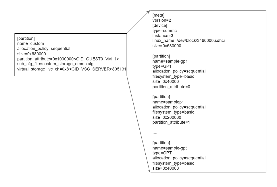 In the preceding example, the
 custom partition is the
container partition. In order for the flashing tools to create GPT partition
layout, the first partition must be of type GP1 and the last partition must
be of type GPT. Flashing tools would create GPT primary and back up
partitions when such an arrangement exists.
Multiple GPT partitions can be added for the same guest. The GPT primary and secondary are generated by using the container partition name as prefix.
Example Changes for :only:`qnx:QNX` :only:`linux:Linux` GOS VM
Configuration files are in the following folder:
<top>/<NV_SDK_NAME_FOUNDATION>/platform-config/hardware/nvidia/platform/t264/automotive/pct/drive_av/<PCT>

NOTE:
    <PCT> is  linux.
ENABLE_TEST_GPT_L3PT := in the profile.mk file is knob to adding GPT
custom partition. ENABLE_TEST_GPT_L3PT is defined by default in the
prod_debug_extra PCT variant of standard, production, and safety packages
for sample of adding GPT partitions.
More custom partitions can be added with the same guest ID in the
partition_attribute. The container partition name is used to differentiate
between multiple GPT partition tables for the same guest.
In the preceding example, the GPT is defined within the sub-configuration file custom_storage_emmc.cfg.
The following example shows how to define GPT L3 partitions.
<top>/<NV_SDK_NAME_FOUNDATION>/platform-config/hardware/nvidia/platform/t264/automotive/pct/drive_av/<PCT>/custom_storage_ufs.cfg

[meta]
version=2

[device]
type=ufs_lun
lun=0
linux_name=/dev/block/a80b8d0000.ufshci
size=0x380000

[partition]
name=sample-gp1
type=GP1
allocation_policy=sequential
filesystem_type=basic
size=0x40000
partition_attribute=0

[partition]
name=samplep1
allocation_policy=sequential
filesystem_type=basic
size=0x100000
partition_attribute=1

[partition]
name=samplep2
allocation_policy=sequential
filesystem_type=basic
size=0x100000
partition_attribute=1

[partition]
name=samplep3
allocation_policy=sequential
filesystem_type=basic
size=0x100000
partition_attribute=1

[partition]
name=sample-gpt
type=GPT
allocation_policy=sequential
filesystem_type=basic
size=0x40000
Caution and Verification#
The size of the device at L3 matches the size of the extended custom partition at L2:
The custom container has three partitions each of 1 MB. Note that the filename is not specified above. If file is not specified, flash tools will not create any images for these partitions but the space is allocated and will be formatted if specified. If an image is required, update the partition within the custom cfg file accordingly to add the filename field and point it to the file you want to flash.
Once booted with upper changes, the GPT partitions are enumerated as virtual block devices in Guest OS.
For Linux, if the container block device is enumerated as /dev/vblkdev32, then the individual partitions are /dev/vblkdev32p1, /dev/vblkdev32p2, and /dev/vblkdev32p3.
Configuring the UFS Stream ID for Virtualized UFS Partitions#
The ufs partitions that are virtualized will need an unique stream ID
associated with it. To make this work storage config is extended with a new
attribute ufs_stream_id. The attribute ufs_stream_id become
auto-configured by the auto-config frame work
These stream ID macros are defined in tegra264-smmu-streamid-ufs.h.
<top>/<NV_SDK_NAME_FOUNDATION>/platform-config/hardware/nvidia/t264/nv-public/include/kernel-t264/dt-bindings/memory/tegra264-smmu-streamid-ufs.h
#define TEGRA264_SID_UFS_X  (TEGRA264_SID_UFS + 0x01)
#define TEGRA264_SID_UFS_Y  (TEGRA264_SID_UFS + 0x02) /*Here X to Y  bandwith in a value */
Additionally, the above-mentioned mempool and IVC queue need to be added to the
resource.yml file in the format provided below. The bandwidth for the
mempool and IVC queues is configured sequentially using the auto-configuration
method from the resource database.
<top>/<NV_SDK_NAME_FOUNDATION>/virtualization/pct/make/t264/storage_config_db/db/resource.yml

ufs_stream_id: {
        val: [TEGRA264_SID_UFS_X-TEGRA264_SID_UFS_Y],Here X to Y  bandwith in a value==>#
...
...
...
}
Out Directory of Auto-config Storage Framework:#
Once the Bind Partition process is completed, the auto-configured dataplanes and the required DT nodes with auto -configured IVC queues , mempool ID and ufs_stream id can be found in the following location:
Note
Provided the out directory for the PCT : LINUX
<top>/<NV_SDK_NAME_FOUNDATION>/virtualization/hypervisor/t26x/configs/t264ref-release/pct/<BOARD-NAME>/auto_config/out

tree -l
.
├── auto_config_linux_gos0_storage.dtsi
├── boot_chain_c_storage.cfg
├── boot_chain_storage.cfg
├── custom_storage_ufs.cfg
├── drive_updatedu_hvrtos.dt
├── global_storage.cfg
├── linux_chain_c_storage.cfg
├── linux_storage.cfg
└── storage_linux-gos0.dts

0 directories, 9 files
auto_config_linux_gos0_storage.dtsi → Consist of auto-generated Adddres-space node , context bank node, memory mapping node and also virtual storage DT node like below
<top>/<NV_SDK_NAME_FOUNDATION>/virtualization/hypervisor/t26x/configs/t264ref-release/pct/<BOARD-NAME>/auto_config/out/auto_config_linux_gos0_storage.dtsi


tegra_virt_storage79{
    compatible="nvidia,tegra-hv-storage";
    status="okay";
    iommus=<&smmu1_mmu 0x2a01>;
    instance=<1>;
    ivc=<&tegra_hv 59>;
    mempool=<19>;
    partition-name="gos0-shared-pers";
    };
Also verify the configurations using the auto-configured UFS Stream ID.
<top>/<NV_SDK_NAME_FOUNDATION>/virtualization/hypervisor/t23x/configs/t234ref-release/pct/<BOARD-NAME>/auto_config/out/global_storage.cfg

[partition]
name=gos0-shared-pers
allocation_policy=sequential
filesystem_type=basic
size=0x10000000
filename=<LINUX_OUTDIR>/target_rootfs_user_thor_metadata.img
ispersistent=yes
virtual_storage_ivc_ch=0x8316133b /* Auto-configured ivc channel */
ufs_stream_id=0x2a01     /* Auto-configured ufs stream id */
partition_attribute=0x1  /* Auto-configured partition_attribute */
virtual_storage_ivc_ch=0x8316[Hex value of Mempool Num][Hex value of Ivc Queue Num]
Note
The 32-bit value of virtual_storage_ivc_ch can be broken down as follows:
Bit |
Description |
|---|---|
[31] |
Is Virtual Storage Flag [virt = 1, non-virt = 0] |
[30:24] |
Storage Server ID [int value from 0-0x7F] |
[23] |
Shared Partition Flag [shared = 1, exclusive = 0] |
[22] |
RESERVED |
[21:18] |
Partition Priority. [Values from 1 through 5, where 1 is the highest priority.] |
[17] |
Disable pass-through [1 = Disable, 0 = Enable] |
[16] |
Read only flag [RO =1, RW = 0] |
[15:8] |
Mempool ID [int value from 0-0xFF] |
[0:7] |
IVC Queue ID [int value from 0-0xFF] |
Note
The 32-bit value of partition_attribute can be broken down as follows:
Bit |
Description |
|---|---|
[31] |
Set if the partition’s storage device is the boot medium for the guest. |
[30] |
Set if the partition holds a blob for boot-chain (and sub_cfg_file is present if the partition is present on the global boot device). |
[29] |
Set if the partition holds a blob for guest partitions (and sub_cfg_file is present). |
[28] |
Set if the partition holds a blob for user partitions (and sub_cfg_file is present). |
[0:4] |
guest ID [int value from 0-31] |