Storage Server Architecture#
With the NVIDIA Storage virtualization architecture, multiple Guest OSes can access dedicated segments of physical storage without affecting other guest OSes. To share the same storage device between the different guest OSes, the storage virtualization architecture provides:
Virtual Storage Client Driver (VSCD) in the guest OS for accessing storage. (The native storage driver in the guest OS is disabled when storage virtualization is used.)
HVRTOS based Storage Server to manage the storage device. The storage server processes the storage access request on the behalf of the guest.
Storage Virtualization Architecture#
The storage virtualization architecture is as follows:
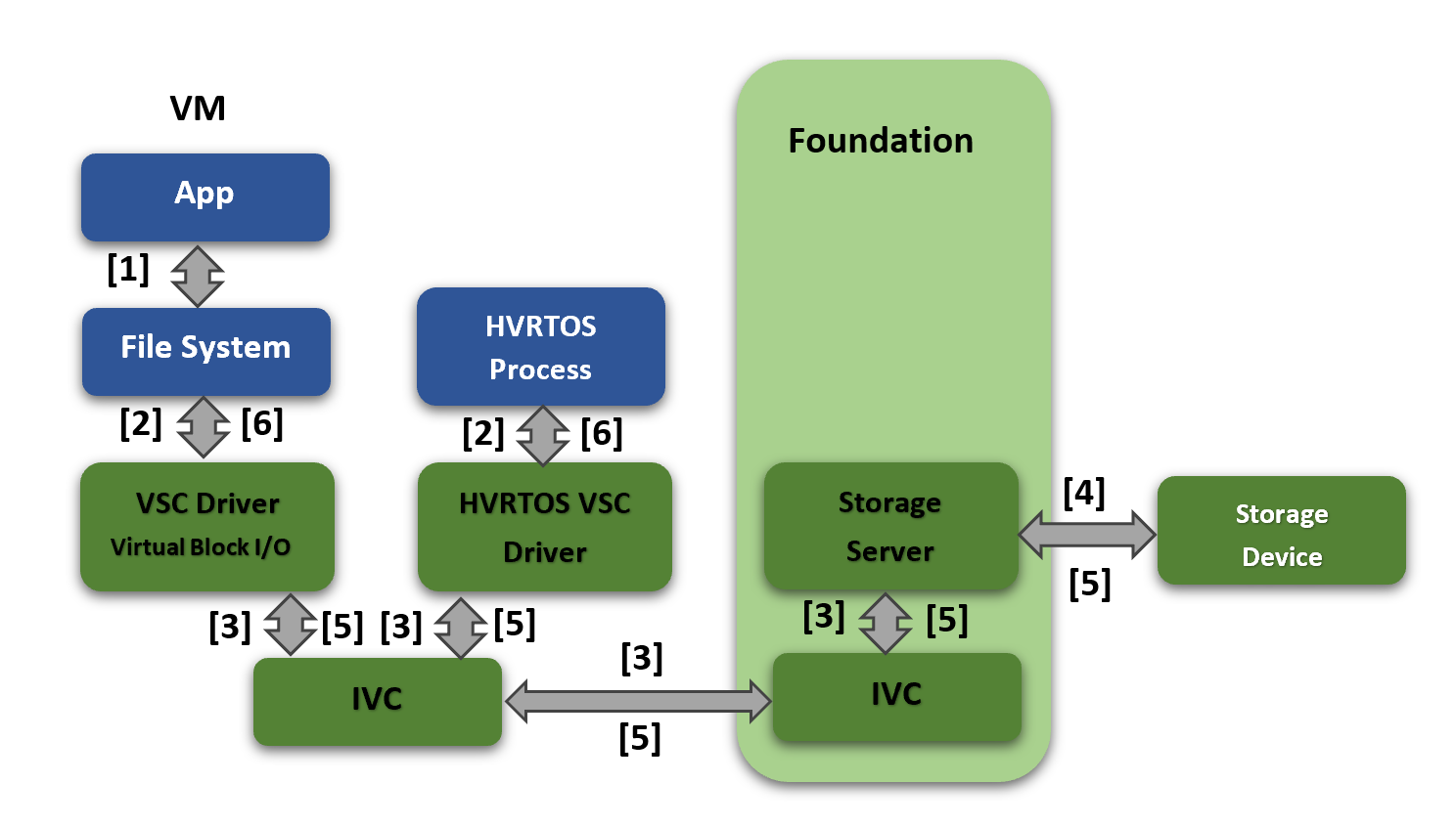
The component interactions are described below.
Step |
Interaction |
|---|---|
1 |
In case of Guest OS, The application makes a read/write request to the file system. |
2 |
In case of Guest OS, The file system sends the request to the VSC driver via block layer. In case of HVRTOS Process, the HVRTOS process sends the block request to the HVRTOS VSC driver directly |
3 |
In case of Guest OS/HVRTOS process, the VSC driver/HVRTOS VSC driver sends the request to the storage server using the underlying IVC mechanism. |
4 |
The storage server reads/writes data from/to the physical storage device. |
5 |
When the actual transfer from/to storage device is complete, the storage server sends a completion message along with data to the VSC client driver in the guest/HVRTOS VSC client driver in the HVRTOS process. |
6 |
In case of Guest OS, the VSC client driver returns status and data to the file system and the application. In case of HVRTOS process, the HVRTOS VSC client driver returns status and data to the HVRTOS process. |
The storage controller-supported features are as follows:
Controller |
Supported |
Not Supported |
|---|---|---|
eMMC (Only on T234) |
Speed: HS400 |
Command Queue |
NVIDIA mnand refresh and health status |
HPI |
|
RPMB |
||
UFS |
HS-G4 |
|
SCSI commands |
Note
RPMB (replay-protected memory blocks) is not supported on eMMC or UFS storage for DriveOS 7.0. Any data that requires RPMB protection must be on the SPI-NOR device, which does support RPMB.
Virtualized Storage Device Names#
On Linux, virtualized storage is named vblkdev<id> and MMC/SDCard is named mmcblk<id>.
mNAND Utilities Support#
The storage server allows mNAND commands to be issued by the following mNAND utilities running on any guest OS.
Utility |
Description |
|---|---|
mnand_hs |
Displays health and status of onboard eMMC. |
mnand_rfsh |
Issues refresh commands at a controllable rate. |
For more information about the use of the mNAND utilities and options, refer to “mNAND Utilities” chapter in the NVIDIA DriveOS 7.0 SDK Developer Guide.
To run mNAND utilities on Linux, execute:
/home/nvidia/mnand_<xxx> -d /dev/vblkdev<id> [<options>]
Where:
<xxx>represents the distinguishing part of the utility name (mnand_rfsh and so on).<id>identifies the virtualized storage device that you want to check.<options>is one or more command-line options (optional).
Overhead in CPU Utilization#
In a multi-threaded storage server, one of the threads performs all hardware transactions, such as requesting submission to and fetching responses from the hardware. This thread is called as Hardware Resource Owner (HRO). For NVIDIA DRIVE® 7.0 program, the HRO role is statically assigned to one of the threads (running on PCPU2). If a request arrives on a core other than an HRO-pinned core, it is received and queued by the server thread running on that core and it signals the HRO core to submit the request further to hardware. This will cause an overhead due to additional context switches on HRO core and IPI processing, which accounts for approximately 20% additional CPU utilization in the worst case.
To mitigate this overhead for optimal CPU utilization, Guest OS VSCD processes submits the storage requests on the same core where Storage Server HRO runs (VCPU corresponding to LCPU2).
Storage Priority Scheduling and Requests Latencies#
Priority Scheduling
Storage Server does priority scheduling of requests as per the virtual storage partition priority.
In PCT storage configuration, priority is set for each virtual storage partition.
If there are multiple outstanding requests of different priority partitions, then Storage server first process the requests of high priority. Among equal priority, Storage Server does round robin scheduling of requests.
Latencies
For UFS storage access if “low priority virtual storage partition requests are already queued and after that if there are “high priority virtual storage partition” requests queued then, there can be delays in getting responses for the high priority virtual storage partition requests due to already existing low priority requests queued.
This is due to UFS device queue length has a direct impact on the initial latency for high priority virtual partitions requests. When all 32 slots of the device queue are occupied by already queued low priority virtual storage partition requests and after this if a high priority virtual storage partition request comes, then the high priority request will not be queued until at least one response for the already queued low priority request comes. It is possible that by the time the first response comes for the low priority requests, the rest of the low priority requests in the UFS device queue could have transitioned to active state(Enabled). Due to this, high priority virtual storage partition requests will be processed by device only after processing all existing queued low priority requests.
UFS device provides a way to specify hardware priorities for the queued requests. For Micron UFS, there are 3 levels of priorities supported and for Samsung UFS two levels of priorities supported. Even with these hardware priorities, if the already queued requests to the device gets transitioned to active state then they can’t be preempted to process the high priority requests.
To control the latencies for the high priority requests, a DT configuration option is provided to users to configure the UFS device queue length, so that the latency for high priority requests can be controlled.
Update the DT property below under Storage Server UFS DT node “ufshci@2500000 {” . DTS file name: . t23x-vsc-server.dts:
“nvidia,max-device-queue-len” = <1 to 32>
By default, 32 device queue length is assumed if the above DT property is not provided.
Note
If the device queue length is reduced then there is an opposite effect on the throughput. Effect on throughput drop will be more if lesser the device queue length.
Storage Throughput
For better storage throughput it is recommended to send as much as possible larger size requests from the applications.
For EMMC , the maximum size read/write request from VSCD to storage Server is 512KB.
For UFS, the maximum size read/write request from VSCD to storage Server is 4 MB
Sending smaller size requests less than above will lead to more number of requests to device, which may have negative impact on storage throughput.
Time Slice Configurations for Guest OS and Storage Server#
To provide best possible time slice configurations for the Guest OS and the storage server, performance measurements were done.
The following time slice values are configured after analyzing the results:
Storage server time slice
40 us for HRO Core (core on which “Hardware Resource Owner” thread runs (LCPU2))
20 us for Non-HRO Cores
Guest OS (AV VM) time slice
On HRO core (LCPU2, where actual storage hardware transactions are handled (request submission and response handling)).
400 us - If Guest OS is QNX
40 us - Otherwise
25 ms for all other VCPUs
The proposed time slice configurations take consideration of the tradeoff between CPU utilization and storage performance.
Increasing Guest OS time slice (for LCPU2) impacts storage performance negatively, but guaranteeing more CPU (LCPU2) for the Guest OS.
Reducing Guest OS time slice (for LCPU2) has no negative impact on storage performance, but the Guest OS LCPU2 time slice might be taken away due to some worst-case scenario. Note that, in such case, time sensitive or safety critical applications should not be run on LCPU2 core.
Note
The Priority of the storage server is set the same as that of Guest OS VM.
EMMC Device Lifetime#
NAND devices have limited programand erase cycles for its blocks, after which the devices are not functional for the storage use cases. For example, EMMC devices that are part of NVIDIA DRIVE AGX Orin™ SCL have a budget of 3000 P/E cycles for MLC.
The EMMC device lifetime primarily depends on the storage use cases that define the storage access pattern. Consult storage device vendors for the initial EMMC device lifetime estimate based on the product storage use cases and evaluate if it meets the product lifetime.
Next, monitor the “average block erase counter” and “lifetime percentage” of EMMC. The “average block erase counter” indicates how many P/E cycles of EMMC are consumed out of the total P/E cycle budget (such as 3000 P/E cycles). Monitor these parameters on the target system (such as once a day) to check if the EMMC is aging out faster than intended for the lifetime. Use mNAND tools to obtain parameters.
EMMC Device Latencies#
EMMC device firmware internally completes BKOPS (background operations) for storage maintenance, such as wear leveling, garbage collection, refresh, and bad block management pushing data from SLC storage to MLC/TLC storage. BKOPS results in varying latencies when accessing the storage.
For example, for the Micron Pearl EMMC device, BKOPS delays may extend up to 500ms. In rare cases it can go to 3 or 5 seconds, but this is unusual due to power loss during instant garbage collection or bad block replacement.
Following are general guidelines to reduce the latencies. For additional assistance, consult with storage device vendors.
Avoid random writes of smaller request sizes. Instead do sequential writes
The performance will be less if more the storage area is occupied; keep storage area free as much as possible. Enable the discard option in filesystems
Use the
discardoption during filesystem mounting so that the user space Erase operation would lead to the file system sending a Discard or Erase request to the eMMC device.In Linux, the
discardoption can be added during ext4 filesystem mounting
mount –o discard –t <fs type> …
Keep at least 1GB of free space on eMMC devices to reduce garbage collection and reduce the time taken for BKOPS by the eMMC firmware.
Functional Constraints#
The storage server imposes the following constraints on users and system integrators:
Its assumed that users will perform integrity checks on the storage data to verify accuracy of the data.
Its assumed that users of storage will implement mechanisms, such as timeout, to monitor forward progress if required.
It is assumed that NVIDIA DriveOS will go through a graceful shutdown sequence, which sends a shutdown notification to the storage server. In the case of an abrupt shutdown, the data in storage device caches could be lost, resulting in some storage device writes not being persistent.
The storage server should have a graceful shutdown each time, and any failure in this regard might result in storage device initialization taking longer during the next boot cycle and impacting boot KPIs.
The storage server completes a majority of its processing on LCPU-2. For DriveOS use cases, LCPU-2 CPU BW availability needs to be evaluated for its impact.
For optimal storage throughput, always en-queue large-size requests as much as possible.
The storage server supports UFS device queueing for the requests. UFS device queue length has a direct impact on the initial latency for high-priority virtual partitions. When all 32 slots of the device queue are occupied by low-priority requests and a high priority request comes, the high-priority request will not be queued until at least one response for the already queued low priority request comes. By the time the first response arrives for the low priority requests, the rest of the low priority requests in the UFS device queue could have transitioned to an active state (Enabled). If storage use cases have strict latency requirements, configure the device queue length (provided as a DT property) to the optimum value after considering the tradeoff between latency and throughput. If the device queue length is reduced, then there will be a negative effect on throughput.
It’s the responsibility of the system integrator to tune the virtual storage partitions priority to meet the latency and bandwidth needs of the system.
Depending on the virtual storage partitions priorities, if high-priority virtual storage partitions continuously consume the storage bandwidth, low-priority virtual storage partition requests may potentially be starved. This is because of storage priority-based scheduling, in which high-priority requests are processed before low priority requests. Storage users should consider this for accessing the storage. 1. DriveOS users may schedule the storage access so that low-priority storage user requests may not timeout due to high-priority storage requests 2. Low-priority storage access can be retried on timing out, or set the timeout based on the priority. The storage client driver (VSCD) provides a configurability option to set the timeout via DT.
For SDMMC and UFS, performance varies based on the amount of the storage occupied in the storage device. Consult with storage vendors for additional information.