Boot ROM Core Concept#
The first stage of boot starts when BPMP and PSC execute read-only memory code embedded in the chip, known as the Boot ROM code. This code:
Initializes boot media I/O controllers (e.g., QSPI, UFS, USB).
Loads early boot components from selected internal or external media.
Loads OEM and NVIDIA cryptographic keys for boot firmware signing and encryption.
Authenticate, decrypt, and execute the next stage of boot firmware.
The initial boot medium is primarily selected by using a strap resistor configuration BOOT_SELECT_CODE.
This may be overridden by burning fuses, specifically the RESERVED_SW or optionally BOOT_DEVICE_INFO fields.
The early boot flow sequence is as follows:
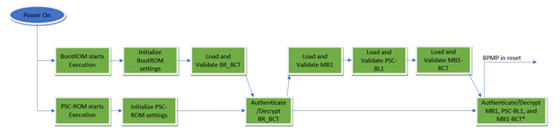
The Boot ROM first loads a boot configuration table, named the BR-BCT, to configure early boot:
Boot chain storage offsets for MB1, PSC-BL1, and MB1-BCT
Boot chain parameters
Debug control flags
Secure boot public key selection
A complete group of boot firmware components is known as a boot chain. This is detailed elsewhere. Tegra chips support flashing up to 4 boot chains to allow redundant or backup images, and to deal with firmware update errors. If one boot chain aborts boot, the system resets and tries the next boot chain.
Note
On Orin, the boot chain is selected in a single BR-BCT field. On Thor, the boot chain is selected using GPIO configuration, with fallback to trying boot chain in-order.
The BR-BCT is integrity-checked using SHA-512.
On security_mode fused production boards, the BR-BCT must be signed by the included public key, and the public key digest is validated against the public key digest fuses.
For more information, refer to section Secruity Framework.
The BR-BCT layout is not customer-configurable, except for reserved customer_data fields.