Layer-2 Bridge in Orin
DRIVE OS supports low bandwidth layer-2 network bridge between 2 or more Tegra ethernet MACs using ethernet MAC HW virtualization, ethernet MAC HW Flexible Receive Parser (FRP) features and brctl (from bridge-utils package in Linux).
The Layer-2 bridge is in "deny all" mode for all unicast & multicast packets. To allow packets through this bridge, FRP rules need to be programmed in the ethernet MAC.
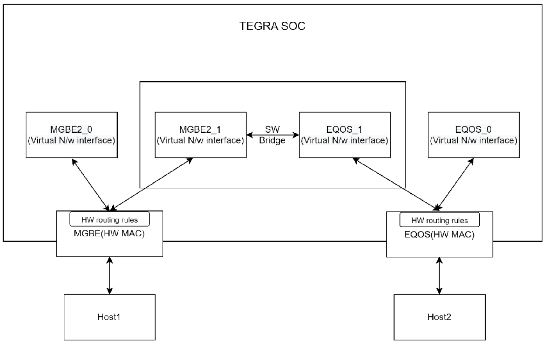
A Layer-2 bridge is already deployed (without FRP rules) in NDAS usecase (starting 6.0.7.0) between MGBE2 & EQOS ethernet MAC. The block diagram is shown below.
Creating the Bridge
- Virtualize the MAC interfaces using the steps mentioned in "Ethernet VF configuration" section under Networking
- Enable creating of Layer 2 nw bridge by updating the device tree with device node ' ndas_nw_bridge ' and ' status = "okay".
- Create the Layer 2 bridge interface and add the interfaces using brctl (from bridge-utils package utility).
- Assign zero IP address to the interfaces participating in bridge function.
- Set up FRP rules to allow packets through the Layer-2 bridge. Refer below section for setting up FRP rules.
FRP Rules Setup Examples
This Layer-2 bridging solution requires combination of Layer-2 Destination Addr filtering rules and FRP rules in HW MACs participating in the bridging.
-
- A sample tool named
nvether_sample_appneeds to be generated based on Networking header files packaged in include path of AV+L DRIVE OS SDK package, The tool is required to configure the FRP Rules and L2 filter rules. - Following parameters need to be configured statically.
- MAC address of devices connected across the layer-2 bridge.
- Multicast addresses based on use case.
- VLAN ID used for communication across the layer-2 bridge.
- A sample tool named
Refer to the Exported Networking element APIs in API reference section for the list of IOCTLs used by sample tool.
Example setup details:
| Interface Name | MAC | IP |
|---|---|---|
| Host1 (host1_eth0) | b2:fc:eb:b3:f6:90 | 192.168.90.10 |
| VLAN201 (host1_eth0.201) | b2:fc:eb:b3:f6:90 | 10.0.1.10 |
| Host2 (host2_eth0) | 8a:05:14:b6:23:01 | 192.168.100.10 |
| VLAN201 (host2_eth0.201) | 8a:05:14:b6:23:01 | 10.0.2.10 |
| MGBE2_0 | 7e:98:e2:75:ee:56 | 192.168.90.20 |
| MGBE2_1 | 7e:98:e2:75:ee:57 | 192.168.90.40 |
| EQOS_0 | ca:46:a3:f7:fc:16 | 192.168.100.20 |
| EQOS_1 | ca:46:a3:f7:fc:17 | 192.168.100.40 |
Setup routing rules on Linux hosts

Example Use Cases
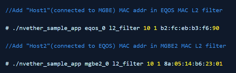
Add MAC L2 filter rule to allow packets to reach FRP engine of the ethernet MAC interface. This is common for use case 1 and 2.
Use case 1: Allow ping through the bridge using unicast MAC DA based filter.
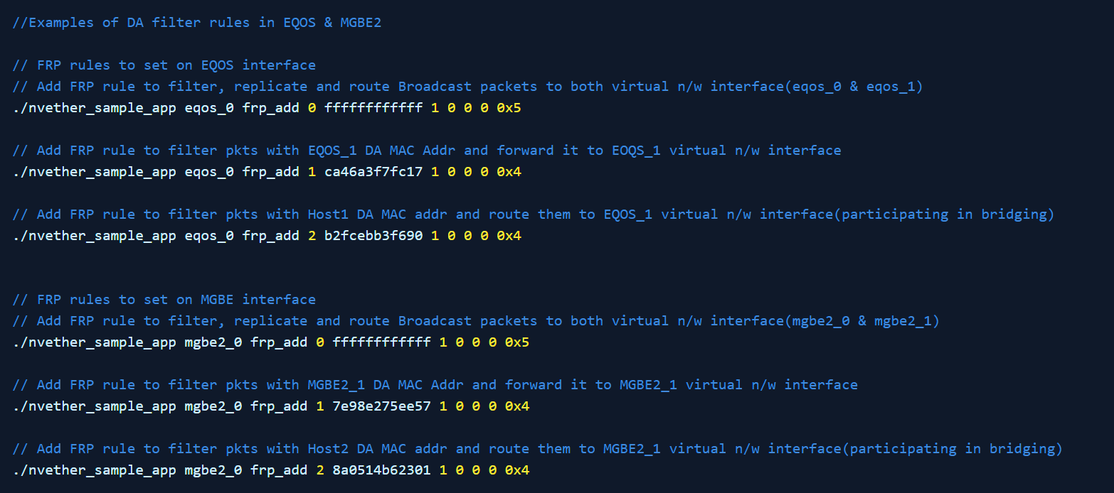
Once the rules are set. Ping Host2 from Host1 and vice versa. Ping should pass.
Use case 2: Allow VLAN based ping through the bridge using VLAN Tag + Unicast(UC) MAC DA based filters.
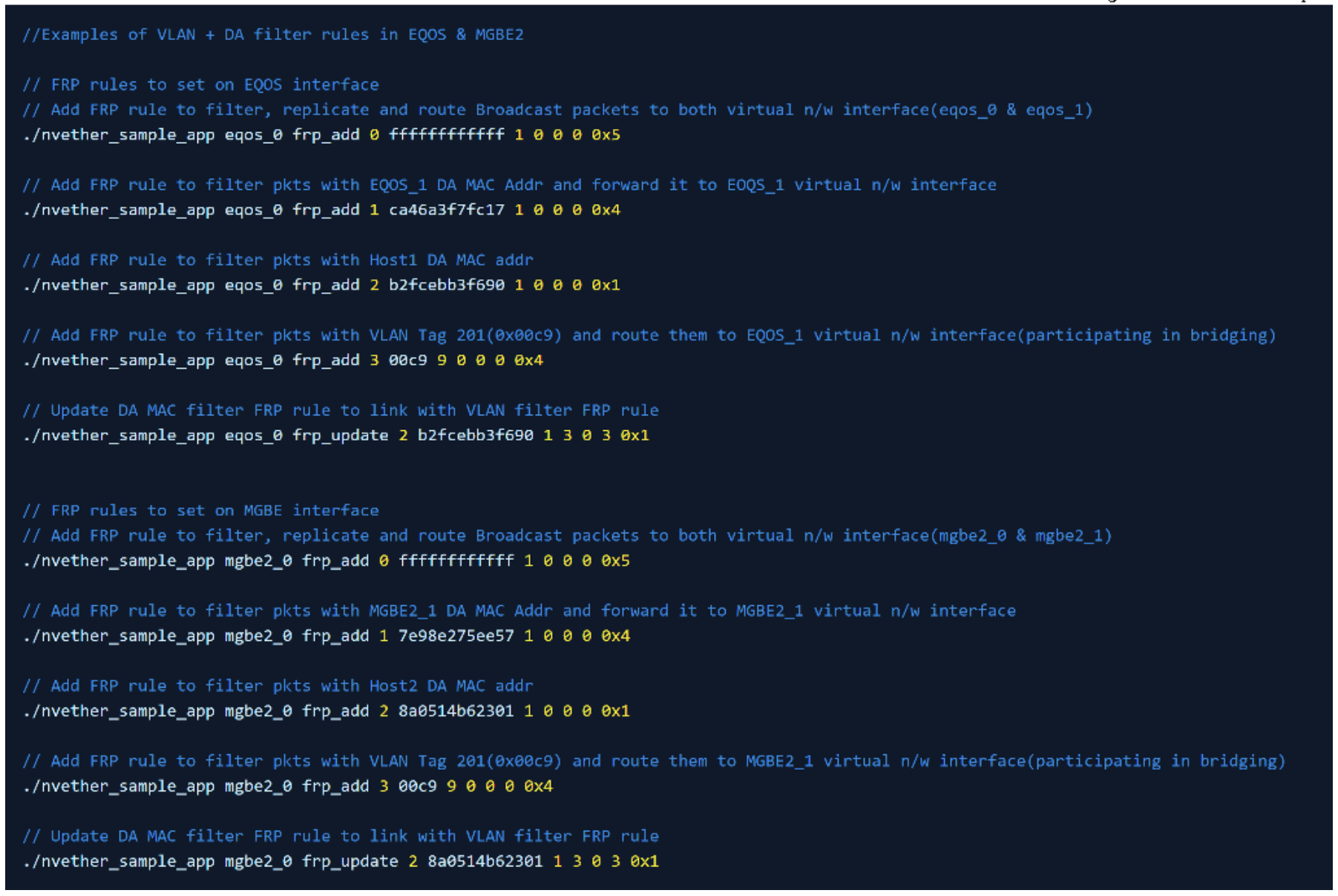
Once the above rules are set, ping from Host1 to Host2 over VLAN and vice versa should pass and ping from Host1 to Host2 over base interface and vice versa should fail.
Use case 3: Allow Multicast packets through the bridge using Multicast DA based filter.

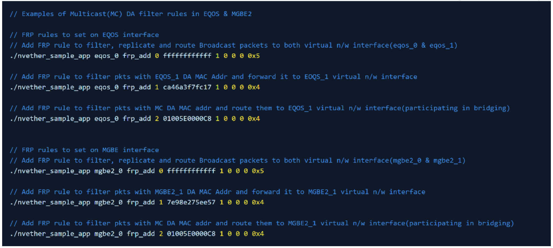
Once the rules are set, start the application to send packets with MC MAC DA addr as 01:00:5E:00:00:C8 on Host1 and on Host2 observe the MC packets reaching it using capture tool and vice versa.
For more details on FRP rules, refer to FRP Validation under Networking.
Limitations
- All interfaces used across the layer-2 bridge must have same MTU size configured. Packets transmitted by devices must be limited to the configured MTU size.
- This solution is designed to support only low bandwidth use cases like Diagnostics System, etc. needed only in non mission mode.
- The design assumption that both virtual interfaces added to the Layer-2 bridge are owned by a single VM.