Lens Matched Shading and Unreal Engine 4 Integration Part 1
Introduction
Lens Matched Shading (LMS) is one of the new technologies introduced along with the Pascal architecture, with the specific purpose of improving the performance and efficiency of Virtual Reality (VR) rendering. LMS achieves both better perf and perceived image quality than Maxwell's Multi Resolution Shading (MRS) technique.
While LMS is quite simple and elegant algorithmically, there are many practical issues, optimization strategies and challenges to overcome when integrating it into an actual game engine. In this article, we have gathered the collective wisdom and experiences learned from integrating Lens Matched Shading into Unreal Engine 4, a fully featured game engine with source available.
Lens Matched Shading Intro
Before getting our hands wet in engine integration, let’s start with a short introduction to Lens Matched Shading. In the meantime, feel free to look at this blog done by my colleague Iain which covers the same topic as well: Pascal VR Tech
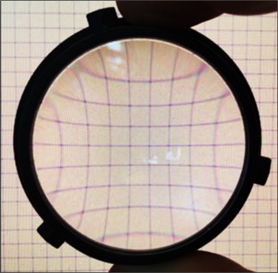
At the end of the rendering pipeline of all VR applications, one of the steps is lens distortion. It warps the rendered image according to the HMD lens profile, so that when you view the post-warped image through the lens, it appears to be undistorted again.
We define shading rate as the number of shading samples per unit area on the framebuffer. The side effect of this lens distortion is that it changes the shading rate of the original image drastically.
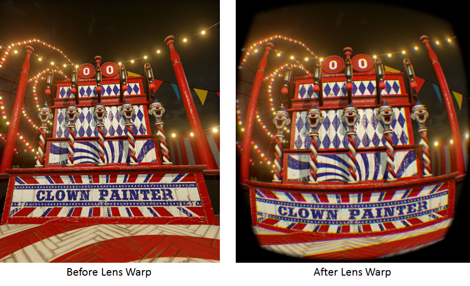
As shown in the figure above, lens distortion significantly squashes the periphery of the image, while enlarging the center, which makes the periphery shading rate higher and the center shading rate lower compared with the original image.
The shading rate distribution after lens distortion is really far from ideal since the periphery receives many more shades per final sample than the central region. Also, viewers tend to focus their attention at the center of the screen, which places these over-sampled areas in their weaker peripheral vision.
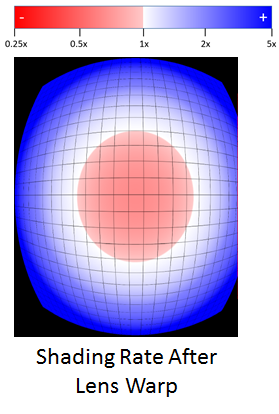
The figure below visualizes the shading rate distribution across a single view on an HTC Vive. It uses 1512x1680 as the actual render resolution and 1080x1200 as the display resolution. It’s clear that even with 140% of super sampling, the central region is still slightly undersampled on the final display, while the periphery is significantly super-sampled (close to 5x).
HMD lenses, like all other lenses, are designed to be sharper at the center and blurrier around the periphery. As we spend more time than necessary resolving shading in peripheral areas of the screen that are then blurred by optical distortions. Therefore if we could somehow control the shading rate to match the lens profile, we could significantly reduce the shading workloads, but also improve the perceived image quality.
One of the ideal ways to address this is to use ray tracing to directly generate a lens warped image so we can matched the lens sample distribution perfectly. However in the world of rasterization we have to use approximation since the lens warp distorts the image in a nonlinear way while rasterization only works on linear data.
Lens Matched Shading is designed to address this problem. As its name suggests, in order to more closely approximate the shading rate distribution of a given lens profile, it modifies the w component of each homogeneous vertex in clip-space, right before the perspective divide, with the following equation:
w’ = w + Ax + By.
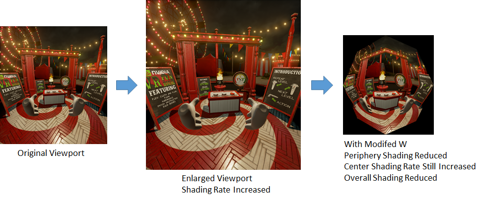
In the equation above w, x and y are all clip-space homogeneous coordinates, A and B are coefficients that control the changing rate of w‘ in X and Y directions. The intuition behind this equation is that w’ is a linear function of x and y. Since the clip-space origin lies at the center of the image, vertices that are at the edge of the image will have a larger w. The effect of this modified w is that, after perspective divide using w’, periphery region are “pulled in” towards the center, shading rate reduced, similar to the lens distortion process described above. What’s different here with lens distortion is that the shading rate of the center is nearly unchanged, since x and y are both close to zero near the center. To avoid any undersampling in the central area we simply increase the resolution of the image. In conclusion, LMS consists of two parts,
- enlarging the image render target size to increase shading rate in the center
- utilizing clip space w modification to reduce the shading rate in the periphery region.
Since w modification keeps the linearity of the data, rasterization still works. And by carefully designing coefficients A and B and properly scaling the resolution we can approximate the shading rate of lenses rather well with Lens Matched Shading, improving the perceived rendering quality. What’s better is that we can also significantly increase FPS by using coefficients that reduce shading rate more in the periphery (considering that they will be blurred by the lens anyway) while still keeping the center shading rate high.
Pre-set Configurations
The values of the coefficients and resolution scale are essential for controlling the distribution of shading rate. In similar fashion to the VRWorks SDK, we’ve also provided three sets of default configurations for both HTC Vive and Oculus Rift: Quality, Conservative, and Aggressive. The following figure visualizes the shading rate distributions for each configuration on an HTC Vive. All shading rate visualizations below use 1512x1680 as the render resolution and 1080x1200 as the display resolution, as recommended by HTC. Same as before, the visualized shading rates are relative to the final displayed resolution.
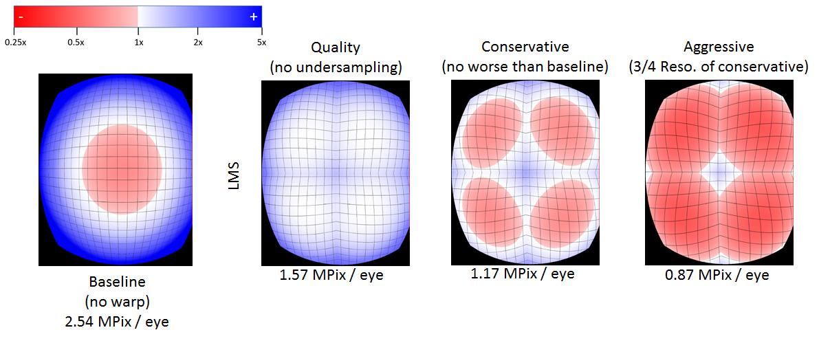
As shown before, the Baseline on the left undersamples the center slightly while significantly supersampling the periphery region. The Quality configuration is designed to match the lens profile closely, with no undersampling across the entire image, while reducing the total number of pixels by 40%. The Conservative configuration is designed so that the periphery is undersampled to the same degree as the center is undersampled in Baseline. And finally, the Aggressive configuration is designed to provide maximum frame rate. It renders ¾ of number of pixels relative to the Conservative configuration, reducing the total number of pixels to roughly 34% relative to the Baseline.
Developers are welcome to create custom configurations for more direct control of balancing performance and image quality depending on the characteristics of the game, however this currently requires modifications to the source code. A new instance of FLensMatchedShading::Configuration will need to be defined in VRProjection.h/cpp.
Aside from pre-set configuration, we have also provided a console variable called vr.LensMatchedShadingResolutionScaling that smoothly scale the periphery shading rate while keeping the center shading rate high. This console variable offers another way of tuning the performance and quality balance for your application.
Comparison with Multi-Resolution Shading
Multi-Resolution Shading (MRS) is another piece of technology that aims at accelerating VR rendering, the introduction to which can be found in Nathan Reed’s VR presentation (see https://d29g4g2dyqv443.cloudfront.net/sites/default/files/akamai/gameworks/vr/GameWorks_VR_2015_Final_handouts.pdf). MRS divides the viewport into nine sub-viewports, and uniformly reduces the shading rate in all corner and edge viewports. Compared with MRS, LMS has the following technical advantages.
-
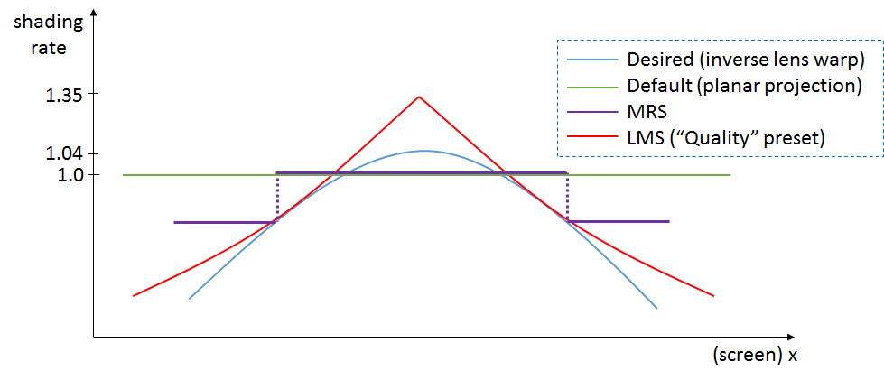
LMS matches closer to the ideal shading rate: its 1/x profile is a better fit than the MRS piecewise constant approximation, as shown in the figure below. Thanks to this:
- LMS uses much fewer shading samples than MRS, or equivalently LMS achieves better image quality with the same amount of samples.
- LMS has a smoother shading rate transition across the image.
- LMS uses only 4 viewports while MRS uses 9. Fewer viewports make it easier to work simultaneously with techniques like Instanced Stereo and Single Pass Stereo. This is because the number of viewports is limited to 16 in the hardware. Fewer viewports also potentially helps with performance.
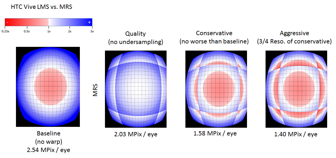
The following graph visualizes the shading rate distribution of MRS. It’s clear that the shading rate changes abruptly at viewport boundaries, and the center of the view still remain undersampled except for the Quality configuration. More importantly, the shading rate is not as low as LMS at each configuration level.
We can estimate the comparative performance gains by computing the number of pixels shaded for matching LMS and MRS configurations. (See the bar chart below) The lower the number of pixels shaded, the better the performance.
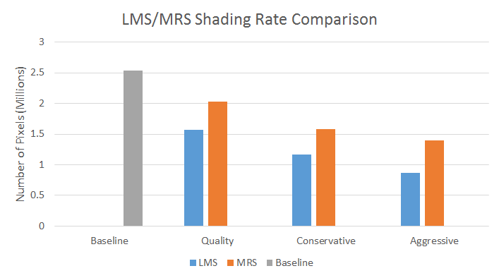
However, we should remember that the number of pixels shaded is not a direct measure of performance, for instance, coordinate remapping is more expensive for LMS than MRS, and there are other workloads in the application like geometry processing and CPU work which will also impact performance. (also please note that LMS is only available on Pascal, while MRS is also supported on Maxwell GPUs).
For a more detailed introduction on the configuration and API definition of Lens Matched Shading, please refer to the documents in the VRWorks SDK.
Continue to Part 2