
Display SerDes in Automotive Systems#
Comprehensive Architecture Guide for Multi-Display Automotive Integration.
Automotive Display Architecture Overview#
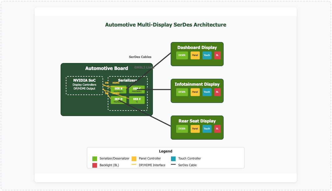
Modern automotive systems feature multiple display screens distributed throughout the vehicle. The automotive board contains multiple serializer hardware chips, each connected to different display panels via cables. Each panel contains a vendor-matched deserializer, creating a distributed display network managed by a single NVIDIA automotive board.
Key Components:
Multiple serializers on automotive board
Vendor-matched deserializers in panels
SerDes cables (GMSL2 links)
Downstream devices (panel, touch, backlight)
Connection Pattern:
One-to-many architecture
Single board to multiple panels
Cable distribution throughout vehicle
Vendor ecosystem consistency
Display SerDes Driver Role#
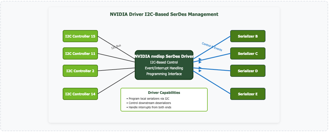
The Display SerDes driver serves as a central control hub that manages the entire SerDes network through I2C-based communication. It provides unified control over both local serializers and remote deserializers across the automotive display ecosystem.
I2C Communication:
Designed for I2C-based serializers
Direct hardware communication path
Real-time configuration capability
Standard I2C protocol compliance
Event Management:
Local serializer interrupt handling
Downstream deserializer events
Real-time status monitoring
Error detection and recovery
Single Driver Module, Multiple Device Architecture#
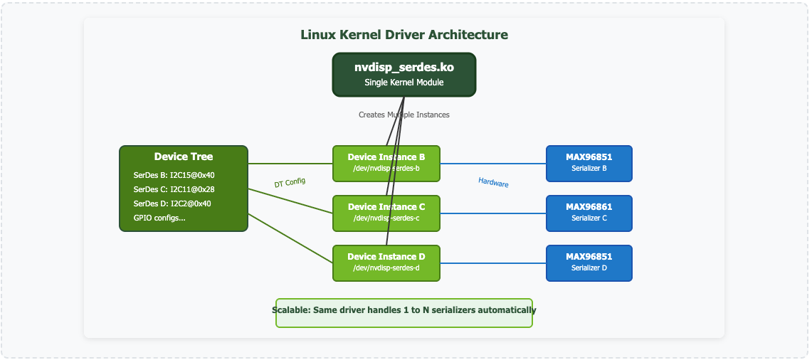
The Display driver follows the standard Linux kernel driver model where one kernel module (nvdisp_serdes.ko) manages multiple device instances. Each SerDes device gets its own /dev/ entry and operates independently while sharing the same driver codebase.
Device Tree Driven:
Each SerDes defined in device tree
Individual I2C address and bus
GPIO configurations per device
Vendor-specific opcode sequences
Automatic Scaling:
Driver scans device tree at boot
Creates instances for each definition
No code changes for different counts
Hardware-agnostic scaling
Device Tree Integration & GPIO Properties#
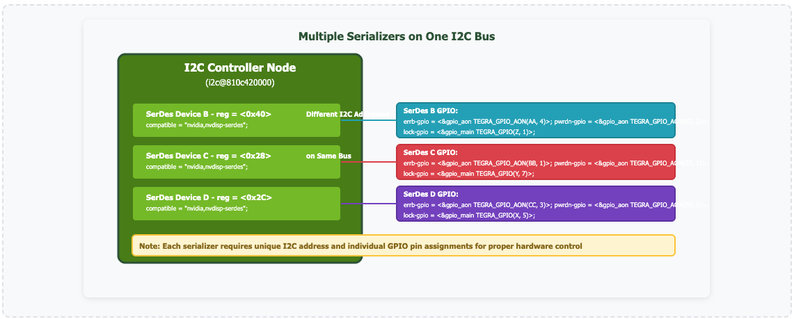
Configuration 1: Multiple Serializers on Single I2C Controller
Configuration 2: Single Serializer per I2C Controller (Typical DTSI Pattern)
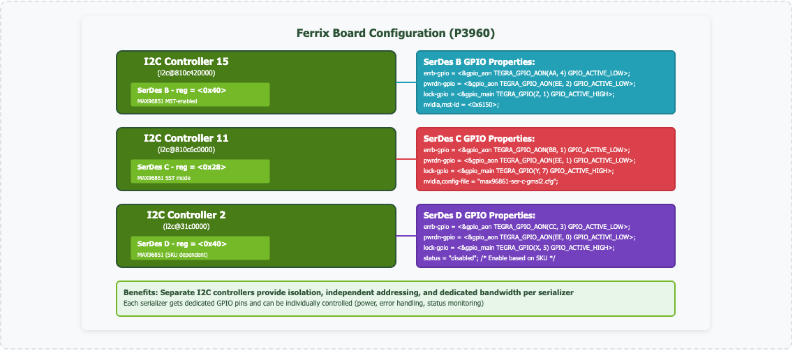
GPIO Signal Functions:
errb-gpio: Error and interrupt signaling (ACTIVE_LOW)
pwrdn-gpio: Power management control (ACTIVE_LOW)
lock-gpio: PLL lock status monitoring (ACTIVE_HIGH)
Custom properties: MST-ID, config files, SKU controls
Hardware Abstraction:
Clean separation: hardware <-> software
Flexible I2C bus assignments
GPIO pin mappings configurable
Platform-independent driver code
Address Management:
Single I2C bus: Requires unique addresses (0x40, 0x28, 0x2C)
Multiple I2C buses: Can reuse addresses (0x40, 0x40)
Vendor flexibility: Different chips, different buses
SKU variants: Enable/disable based on configuration
Configuration Benefits:
Separate buses: Electrical isolation and bandwidth
Individual GPIO: Independent power and error control
Vendor mixing: MAX96851, MAX96861, TI on same board
Flexible scaling: Add/remove serializers per design
Scalable System Integration
System integrators can connect any number of serializers across one or more I2C controllers. The driver automatically adapts to the hardware configuration through proper device tree definitions, making the system highly scalable without requiring driver code modifications. The Ferrix board demonstrates both approaches - dedicated I2C controllers for electrical isolation and performance.
Driver Scope & Architectural Boundaries#
Note
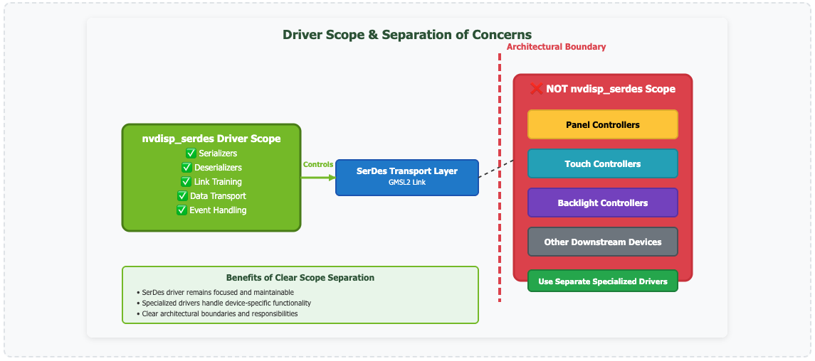
The Display serdes driver architecture strongly discourages using it for programming underlying devices connected downstream of the deserializer. The driver is meant only for serializers and deserializers - not for panel controllers, touch controllers, or backlight controllers.
Handles:
Serializer programming and control
Deserializer configuration
Link training and establishment
SerDes transport layer management
Event and interrupt handling
Uses Separate Drivers:
Panel controller programming
Touch controller management
Backlight control
Camera sensor controls
Any device behind deserializer
Kernel Module Load Sequence & Dependencies#
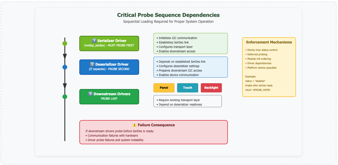
Why Sequential Loading Matters
The dependency chain ensures that each layer is ready before the next one attempts to use it. The serializer driver makes sure to setup the i2c/gpio transport tunnel on GMSL/FPDLink so that other drivers can access their devices connected on downstream deserializer. Breaking this sequence leads to probe failures and system instability.
Operating System Architecture Differences#
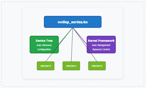
Single Kernel Module: One .ko for all instances
Automatic Discovery: Device tree driven
Kernel Managed: OS handles instantiation
Resource Sharing: Unified memory space
Easy Scaling: No code changes needed
Benefits
Automatic hardware discovery
Dynamic scaling capabilities
Unified resource management
Lower memory overhead
Summary & Key Takeaways#
The Display SerDes driver provides a scalable, centralized solution for managing multiple display systems in automotive environments. Through I2C-based control and device tree configuration, it enables flexible system integration while maintaining clear architectural boundaries.
Automotive Context
Multiple display screens per vehicle
One-to-many SerDes architecture
Distributed deserializers in panels
Vendor-matched SerDes ecosystems
Driver Architecture
Single module, multiple device instances
I2C-based serializer control
Device tree driven configuration
GPIO-based hardware integration
Scalability
Hardware-agnostic scaling
No code changes for different counts
Multiple I2C controller support
Automatic device discovery
Best Practices
Clear driver scope boundaries
Sequential probe ordering
Separation of concerns
OS-appropriate architectures
Critical Success Factors#
Proper Probe Sequence: SerDes → Deserializer → Downstream devices
Scope Respect: Use nvdisp_serdes only for SerDes, not downstream devices
Device Tree Accuracy: Correct I2C addresses, GPIO assignments, and dependencies
OS-Appropriate Design: Leverage Linux auto-discovery vs QNX explicit control