

Frozen Frame Detection#
Introduction#
Frozen frame detection is a feature designed for automotive displays. It continuously monitors whether the display output has become stuck — showing the same visual content across multiple consecutive frames.
The display hardware computes CRC (Cyclic Redundancy Check) values over configurable screen regions every frame. When the CRCs from a region remain identical across a threshold number of consecutive frames, a frozen frame condition is declared, enabling the system to take corrective safety action.
System Overview#
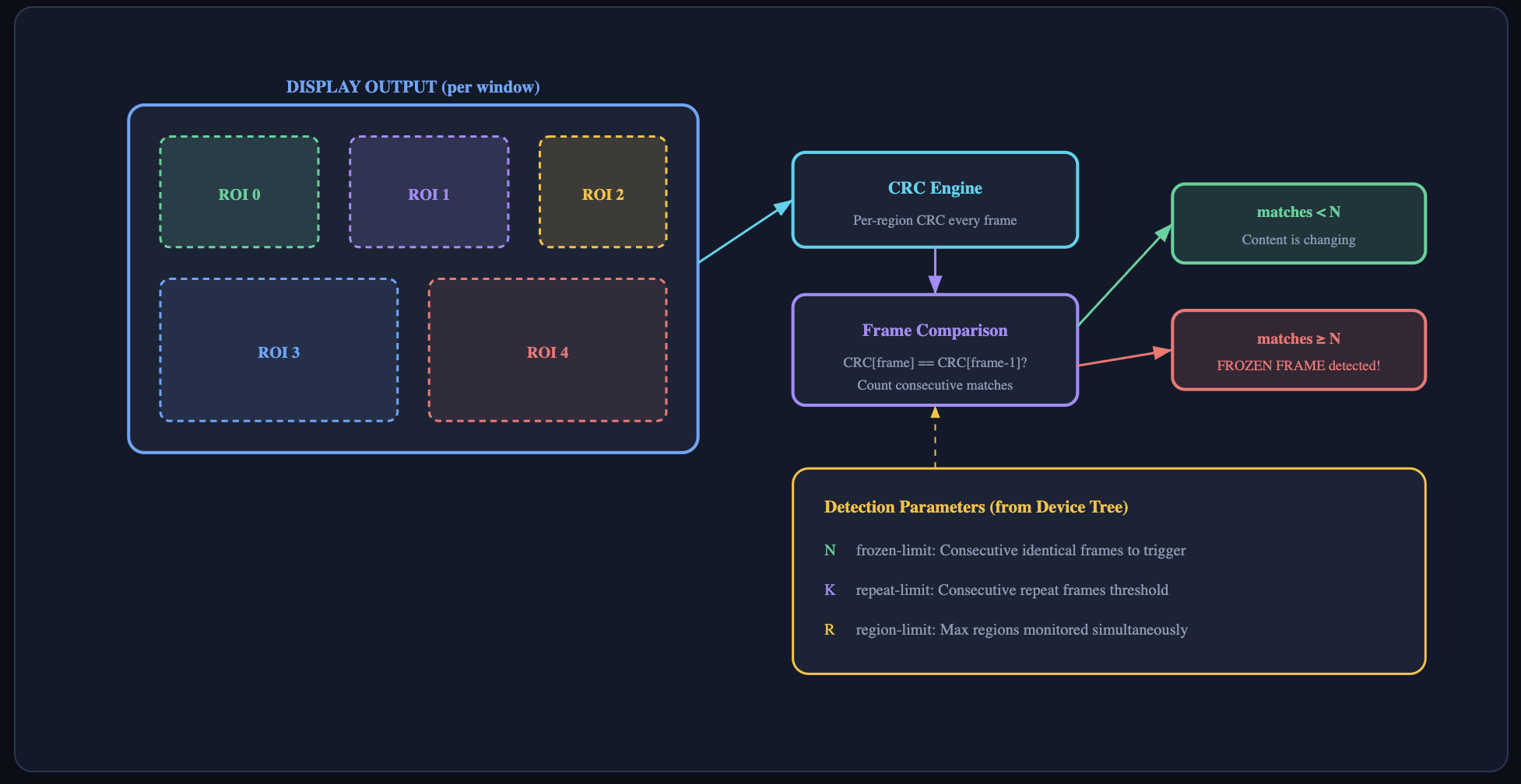
Detection Parameters: N, K, and R#
Parameter |
DT Property |
Type |
Description |
|---|---|---|---|
N |
frozen-limit |
U8 |
Frozen frame threshold. The number of consecutive frames where all monitored regions produce identical CRC values before a frozen frame condition is declared. A higher value reduces false positives but increases detection latency. |
K |
repeat-limit |
U8 |
Repeat limit. The number of times a region’s CRC must match the previous frame’s CRC before a frozen frame condition is declared. A higher value reduces false positives but increases detection latency. |
R |
region-limit |
U8 |
Region limit. The maximum number of screen regions (ROIs) that can be actively monitored for frozen frame detection simultaneously on this head. Limited by hardware CRC resources. |
Note
All three parameters are optional in the Device Tree. If omitted, they default to 0, which effectively disables frozen frame detection for that head. To enable frozen frame detection, all three parameters must be set to non-zero values.
Device Tree Configuration#
Frozen frame parameters are configured under a frozen-frame-detection child node within each display head node of the display configuration in the DTSI file.
display@SOC_DISP_CORE_1_UNIT_ADDRESS {
    heads {
        head-0 {
            hw-head-id = <0>;

            frozen-frame-info {
                frozen-limit = <5>;    /* N: declare frozen after 5 identical frames */
                repeat-limit = <3>;    /* K: repeat-frame threshold */
                region-limit = <9>;    /* R: monitor up to 9 regions simultaneously */
            };
        };
    };
};
Placement: The
frozen-frame-infonode sits alongside other head properties likehw-head-id. One node per head - each head can have independent frozen frame parameters.
Additionally, frozen frame uses are allocated per window. These are configured within each window definition:
windows {
    window-0 {
        window-id = <0>;
        head-id   = <0>;

    };
};
Regions of Interest (ROIs)#
Frozen frame detection monitors specific rectangular areas of the display output called Regions of Interest (ROIs). Each ROI defines a screen rectangle where CRC values are computed every frame.
Constraints
Constraint |
Value |
|---|---|
Max ROIs per open device |
64 |
Max frozen frame resources per window |
32 |
Max frozen frame resources per head |
32 |
Max simultaneously active regions |
Limited by R (region-limit) from DT |
ROI overlap |
fOverlapping frozen frame ROIs are not permitted |
Lifecycle: Enable → Monitor → Disable
1. Register ROIs: Call NVKMS_IOCTL_REGISTER_ROI for each screen region you want to monitor. Store the returned handles.
Enable Detection: On the next flip, set
specified = NV_TRUE,enableFrozenFrameDetection = NV_TRUE, and populate theregions[]array with the registered ROI handles.Ongoing Monitoring: While enabled, the hardware computes CRCs for each configured region every frame. If CRCs match for N consecutive frames across R or more regions, a frozen frame event is raised.
Reconfigure (Optional): To change which regions are monitored, submit a new flip with updated
regions[]. You can add, remove, or replace ROI handles between flips.Disable Detection: Set
specified = NV_TRUEandenableFrozenFrameDetection = NV_FALSEon a flip. The hardware stops monitoring. ROIs remain registered and can be re-enabled later.Cleanup: Call
NVKMS_IOCTL_UNREGISTER_ROIfor each ROI handle to release CRC resources when no longer needed.
Detection Behavior#
When is a Frozen Frame Declared?
The hardware monitors CRC values for each enabled region on every frame. A frozen frame condition is raised when the following occurs:
The CRC value for a region is identical to the previous frame’s CRC value for that same region, for N consecutive frames.
This occurs across at least R monitored regions simultaneously.
The K (repeat-limit) parameter provides an additional threshold for detecting repeated (but not necessarily frame-identical) CRC patterns.
What Happens on Detection?
When the hardware detects a frozen frame condition, the display hardware reports the error directly to the FSI (Functional Safety Island) — the safety monitoring subsystem on Thor. The error does not go through NVKMS or the application.
Display HW detects frozen frame: CRC comparison logic determines that N consecutive identical frames have occurred across R regions. HW reports error to FSI: The nvdisplay hardware block sends an error report to the Functional Safety Island with a reporter ID identifying the source. FSI logs the error: The error appears on the FSI shell and can be observed by the safety monitoring application.
FSI Shell Error Format
Frozen frame errors appear on the FSI shell in the following format:
DemoApp: ErrCode-0x58a5 ReptrId-0xe008 ErrAttr-0x40000897
Field |
Description |
|---|---|
ErrCode |
The error code identifying the type of safety error. The specific code for frozen frame detection is reported by the display HW. |
ReptrId |
Reporter ID — identifies the hardware block that reported the error. The 0xe008 value corresponds to the nvdisplay hardware block. |
ErrAttr |
Error Attributes — additional context about the error, such as which head or region triggered the condition. |
Safety response: The FSI is responsible for triggering the appropriate safety action when a frozen frame error is received. The specific response (for example, switch to a safe-state display, trigger system notification, initiate recovery) is defined by the system integrator’s safety architecture and is not handled by the display driver.
Monitoring during development: To observe frozen frame errors, connect to the FSI shell (for example, via UART) and watch for error reports with the nvdisplay reporter ID
(0xe008). These errors will only appear when frozen frame detection is enabled, and the display content is actually frozen for N consecutive frames.
Best Practices#
Phase |
Content |
|---|---|
ROI Placement |
Choose regions that are expected to change frequently under normal operation. Avoid static UI areas (for example, a fixed status bar) that could trigger false positives. |
Number of Regions |
Monitor multiple non-overlapping regions to increase detection confidence. A single small region may miss partial freezes. The SDK test uses 9 distributed regions as a reference configuration. |
Tuning N (frozen-limit) |
Lower values detect freezes faster but may produce false positives for legitimately static content (for example, a pause screen). Higher values add latency but improve accuracy. A typical starting point is 3–10 frames. |
Tuning K (repeat-limit) |
Set K to a value between 2–8. The SDK test tracks the last 8 frame colors to ensure no accidental CRC collisions within the repeat-limit window. |
Region Size |
Larger regions produce more robust CRC values (less chance of accidental CRC collision). Very small regions may produce identical CRCs across different content. |
Dynamic Content |
If the display legitimately shows static content (for example, a parking screen), disable frozen frame detection via the flip parameter |
Minimum Resolution |
Ensure the display resolution is large enough to contain all defined ROI regions. The SDK test requires at least 1800×900 for its 9-region configuration. |
Clear Unused Slots |
When setting up flip parameters, explicitly set unused |
Performance |
Frozen frame detection has negligible performance impact — CRC computation is handled in hardware and does not affect flip latency or display bandwidth. |