

Multi-Socket Support#
Overview#
The multi-socket platform integrates two Thor SoC chips connected via NVLink-C2C (Chip-to-Chip) under a single hypervisor environment. This dual-chip configuration, also referred to as Dual Thor with NVLink, provides:
2x CPU cores (for the currently supported DRIVE AGX Thor-X devices, 28 cores total vs. 14 cores on a single chip)
Extended DRAM capacity across both chips
Dual iGPU support for compute workloads (for the currently supported DRIVE AGX Thor-X devices, 6 GPC/20 TPCs total vs. 3GPC/10TPC on a single chip)
Additional I/O devices from the second chip
Cache-coherent memory access across both chips via NVLink
A single instance of DRIVE OS manages resources on both chips. One hypervisor assigns CPU cores, DRAM, and device resources from both chips to a single Linux guest VM. Applications running within the VM can access all assigned resources, but should be NUMA-aware to maximize performance.
NUMA Architecture#
What Is NUMA#
NUMA (Non-Uniform Memory Access) is a memory architecture used in multi-processor and multi-chip systems where memory access time depends on the physical location of the memory relative to the processor:
Local memory: Memory within the same chip as the processor. Access is fast and has the highest available bandwidth.
Remote memory: Memory on the other chip, accessed over the NVLink-C2C interconnect. Access incurs additional latency and lower bandwidth due to inter-chip communication.
In contrast, a UMA (Uniform Memory Access) system provides equal access latency to all memory from all processors. NUMA improves scalability by giving each chip its own local memory controller, reducing contention on shared interconnects.
In a Dual Thor with NVLink system, each chip constitutes a NUMA node. The operating system and applications can query which node a CPU core, memory region, or device belongs to, and make allocation decisions accordingly.
Dual Thor Topology#
The Dual Thor with NVLink platform connects two Thor chips on a single board via NVLink-C2C. The NVLink interconnect is invisible to application software — the system appears as a single coherent machine with two NUMA nodes.
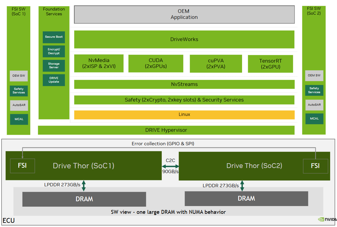
Dual Thor with NVLink-C2C Architecture — two SoCs connected via C2C at 90GB/s, with LPDDR 273GB/s per chip. Software sees one large DRAM with NUMA behavior.#
From the perspective of software running in the Linux VM:
All CPU cores are visible and schedulable
2 iGPUs with all GPC/TPC visible
All DRAM from both chips is addressable
NVLink-C2C is not exposed as a discrete device — cross-chip memory access is handled transparently by hardware
NUMA node information is provided via the device tree, allowing the OS kernel and applications to optimize data placement
How NUMA Impacts System Resources#
CPU
The CPU cores are distributed across two chips. Each chip’s cores are part of a NUMA node. The Linux kernel’s NUMA-aware scheduler minimizes thread migration between nodes. When a thread runs on a core in Chip 0, memory allocations default to Chip 0’s local DRAM.
Unless explicitly overridden, the OS manages NUMA node loading by:
Minimizing thread migration between cores within a node
Minimizing thread migration between NUMA nodes
Optionally migrating threads to the node where their memory resides
DRAM
Each chip has its own local DRAM with dedicated memory controllers. Local DRAM access provides up to 273 GB/s bandwidth per chip. Remote DRAM access (cross-chip via NVLink-C2C) has higher latency and shares the C2C link bandwidth.
By default, the Linux kernel allocates memory local to the CPU node where the requesting thread is running. When local memory is depleted, the kernel falls back to remote memory from the other node. This behavior is configurable via NUMA memory policies (see Memory Allocation and NUMA Policies).
GPU
Each chip contains an iGPU. Both iGPUs are visible to the Linux VM as separate GPU devices and are supported for compute (CUDA) workloads. Memory accesses are fully coherent across both chips, including between iGPU caches.
Applications using CUDA should be aware of which GPU corresponds to which NUMA node to ensure optimal memory placement. Refer to CUDA Toolkit documentation for details: https://docs.nvidia.com/cuda/
Note
Graphics (GFX) and display output are supported only on the primary chip’s iGPU. The secondary chip’s iGPU is available for compute workloads only.
I/O Devices and IPs
NUMA does not only affect CPUs and DRAM. Every hardware IP block is physically attached to one of the two chips. When an IP on Chip 0 accesses memory that was allocated on Chip 1 (or vice versa), that access must traverse the NVLink-C2C link, incurring the same non-uniform latency and bandwidth costs as a CPU accessing remote DRAM. This applies to all IPs — GPU, VIC, ISP, NVENC, PCIe controllers, Ethernet NICs, and others.
For best performance, applications should allocate buffers on the same NUMA node as the IP that will process them. The following table describes IP availability across the two chips:
IP / Resource |
Primary Chip |
Secondary Chip |
Notes |
|---|---|---|---|
CPU Cores (Thor X) |
14 cores |
14 cores |
All 28 cores available to the Linux VM |
DRAM |
Supported |
Supported |
NUMA-aware allocation via kernel and NvMap |
iGPU (Thor X; Compute/CUDA) |
Supported |
Supported |
Both iGPUs available; coherent memory across chips |
iGPU (Thor X; GFX/Display) |
Supported |
Not supported |
Display output on primary chip only |
PCIe |
Supported |
Supported |
Controllers on both chips available to the VM (currently, PCIe RP only) |
Ethernet (MGBE) |
Supported |
Supported |
NICs on both chips for traffic distribution |
Ethernet (EQOS) |
Supported |
Not supported |
Low-bandwidth management NIC on primary only |
NVMe |
Supported |
Supported |
Via PCIe on both chips |
I2C |
Supported |
Supported |
|
SPI |
Supported |
Supported |
|
GPIO |
Supported |
Supported |
|
GIC (Interrupt Controller) |
Supported |
Supported |
Configured to reflect dual-chip topology; appears as single GIC to the OS |
SMMU |
Supported |
Supported |
Page tables present on both chips. |
VIC |
Supported |
Not supported |
Cross-chip sync object wait not supported; see VIC Sync Object Limitation |
ISP / VI |
Supported |
Not supported |
Runs on primary chip only in this release |
Camera Input/CSI |
Supported |
Not supported |
Runs on primary chip only in this release |
NVENC |
Supported |
Not supported |
Runs on primary chip only in this release |
NVDEC |
Supported |
Not supported |
Runs on primary chip only in this release |
NVJPG |
Supported |
Not supported |
Runs on primary chip only in this release |
IOFA |
Supported |
Not supported |
Runs on primary chip only in this release |
Audio |
Supported |
Not supported |
Primary chip only |
Display |
Supported |
Not supported |
Single display controller on primary chip |
UFS (Application) |
Supported |
Not supported |
Application storage on primary chip only |
NvSci (Memory/Sync) |
Partially supported |
Partially supported |
Supports specifying NUMA node for sync objects. NUMA node specification for buffers will be supported in future releases. |
Security Services |
Supported |
Not supported |
Runs on primary chip only in this release |
Memory Allocation and NUMA Policies#
The Linux kernel provides NUMA-aware memory allocation. By default, memory is allocated from the NUMA node local to the CPU where the requesting thread is running. Applications can override this behavior using standard Linux NUMA interfaces.
Linux NUMA Memory Policies#
The kernel supports the following memory policies, configurable per-process or per-memory-region via set_mempolicy() and mbind():
Policy |
Behavior |
Use Case |
|---|---|---|
|
Inherits parent process policy or system default (local preference) |
General-purpose applications |
|
Allocates exclusively from specified nodes; fails if insufficient |
Strict memory placement control |
|
Prefers specified node; falls back to others if needed |
Favors local node with flexibility |
|
Distributes pages round-robin across specified nodes |
Large allocations to balance bandwidth load |
|
Allocates from the current CPU’s local node |
Dynamically follows thread placement |
Using numactl#
The numactl utility provides command-line control over NUMA policy for applications. For example:
To display the NUMA hardware topology:
$ numactl --hardware
To run a program with all threads on NUMA node 0:
$ numactl --cpunodebind=0 ./my_application
To run a program with memory bound to NUMA node 1:
$ numactl --membind=1 ./my_application
NvSci (Synchronization and Buffer Management)#
NvSci supports specifying NUMA node requirements for synchronization objects. When building cross-engine pipelines, NvSci allows producers and consumers to declare their NUMA node preferences, ensuring that shared resources are allocated on the appropriate chip.
VIC Sync Object Limitation#
Important
VIC hardware cannot wait on a sync object that resides on a different chip. This is a hardware limitation of the PreFence sync object mechanism.
In a dual-chip system, sync objects exist on both chips. Each engine’s job execution is confined to its local chip. However, VIC specifically cannot perform a hardware wait on a cross-chip sync object. This means:
A VIC instance on Chip 0 cannot wait on a sync object from Chip 1, and vice versa.
Pipelines involving VIC must ensure that the producer’s sync object is on the same chip as the VIC consumer.
For details on sync objects, refer to the NvSciSync section in the SDK documentation.
Safeguards
The system provides multiple levels of protection against accidental cross-chip VIC sync object usage:
NvSci negotiation: During synchronization object negotiation, NvSci checks NUMA node attributes. If a producer and consumer have incompatible node requirements (e.g., producer on Node 0, VIC consumer on Node 1), reconciliation fails before any hardware operation occurs.
VIC runtime checks: VIC validates the node locality of synchronization objects at bind time and submission time. A mismatch causes the operation to fail with an error.
Workarounds for Cross-Chip Synchronization
When a cross-chip synchronization is required in a pipeline involving VIC, the following alternatives are available:
CPU-based waits: The application can perform a CPU wait on the cross-chip sync object and then signal a sync object local to the VIC instance. CPU-based cross-chip waits and signals are not subject to this limitation. For details on sync objects, refer to the NvSciSync section in the SDK documentation.
Note
Other engines (e.g., NVENC, ISP) do not have this cross-chip sync object limitation. The restriction applies specifically to VIC’s PreFence mechanism.
Enabling Multi-Socket#
Important
Install the NVIDIA DriveOS NVLink SDK prior to executing the following steps. The NVIDIA DriveOS NVLink SDK is only available to NVIDIA NVONLINE users who have the necessary agreements in place. For more details, contact your NVIDIA representative.
To enable multi-socket mode:
Pass the
ENABLE_MULTI_SOCKET=yargument when binding partitions:$ ./make/bind_partitions -b <board_name_of_socket_0> linux ENABLE_MULTI_SOCKET=y
$ ./make/bind_partitions -b <board_name_of_socket_1> linux ENABLE_MULTI_SOCKET=y
CPU Configuration
By default, Thor provides 14 CPUs. When ENABLE_MULTI_SOCKET=y is set, the system configures all 28 CPUs.
GUEST0_CPU_NO_0 := 1
GUEST0_CPU_NO_1 := 2
....
GUEST0_CPU_NO_13 := 0

....

ifeq ($(ENABLE_MULTI_SOCKET),y)
GUEST0_CPU_NO_14 := 14
GUEST0_CPU_NO_15 := 15
....
GUEST0_CPU_NO_27 := 27
endif
Extended DRAM
When multi-socket is enabled, DRAM from the second chip becomes available to the VM.
#ifdef ENABLE_MULTI_SOCKET
    #define GOS0_PHYS_MEM_SIZE_SOCKET1              (8192 * SZ_1MB)
#endif /* ENABLE_MULTI_SOCKET */

....

struct guest_conf gconf[] __attribute__ ((section("guestcfg"))) = {
        [GID_GUEST0_VM] = {
        ....
        .guest_phys_mem_size = GOS0_PHYS_MEM_SIZE,
#ifdef ENABLE_MULTI_SOCKET
        .guest_secondary_socket_phys_mem_size = {
            GOS0_PHYS_MEM_SIZE_SOCKET1,
        },
#endif
Dual iGPU
The second chip’s iGPU is assigned to the GOS0 VM.
 struct guest_io_mapping io_ownership [TEGRA_MAX_DEV] __attribute__ ((section("io_owner"))) = {
     ....
     IO_OWNERSHIP(TEGRA_GPU, GOS0_VM),
     IO_OWNERSHIP(TEGRA_GPU_SOCKET1, GOS0_VM),
Flashing Multi-Socket Platform#
To flash the platform, use the following procedure instead of bootburn.py:
Create BSP Images
Export the
PDK_TOPenvironment variable:$ export PDK_TOP=$PWD
Change to the
drive-foundationdirectory:$ cd drive-foundation/
Clean previous BSP images:
$ sudo rm -rf $PDK_TOP/out/bsp_images_s0 && \
  sudo rm -rf $PDK_TOP/out/bsp_images_s1
Create BSP images for each socket:
$ sudo ./tools/flashtools/bootburn/create_bsp_images.py \
  -b <board_name_of_socket_0> -B qspi -r 1 \
  -g $PDK_TOP/out/bsp_images_s0 -D --chain A -s
$ sudo ./tools/flashtools/bootburn/create_bsp_images.py \
  -b <board_name_of_socket_1> -B qspi -r 1 \
  -g $PDK_TOP/out/bsp_images_s1 -D --chain A -s
Merge the BSP images:
$ sudo rm -rf $PDK_TOP/out/merged
$ sudo ./tools/flashtools/bootburn/create_bsp_images_merge.py \
  --merge $PDK_TOP/out/bsp_images_s0/ $PDK_TOP/out/bsp_images_s1/ \
  --dest $PDK_TOP/out/merged
Verify the merged images:
$ ls -al $PDK_TOP/out/merged/<skuNumber_skuVersion>/flash-images/
Flash the Images
Enter recovery mode:
tegrarecovery x1 on
tegrarecovery x2 on
tegrareset x1
tegrareset x2
Flash the BSP images:
$ cd $PDK_TOP/out/merged
$ export FLASH_DIR=${PWD}$ cd $FLASH_DIR/tools/flashtools/bootburn
$ sudo python3 ./flash_bsp_images.py \
  -b <board_name_of_socket_0> -D \
  -P $FLASH_DIR/<skuNumber_skuVersion> --multi-die
Boot the system:
tegrarecovery x1 off
tegrarecovery x2 off
tegrareset x1
tegrareset x2
Verifying NUMA Configuration#
To verify the NUMA configuration, use the following commands within the Linux VM:
Display the NUMA hardware topology, node distances, and memory per node:
$ numactl --hardware
Run a program with all threads on a specific NUMA node:
$ numactl --cpunodebind=0 ./my_application
Run a program with memory allocations bound to a specific NUMA node:
$ numactl --membind=1 ./my_application