

NVIDIA DRIVE AV Storage Configuration via CUE#
Introduction#
The CUE-based storage configuration flow separates internal and customer configuration, which makes maintenance and updates easier.
CUE is a language and framework for defining, generating, and validating data. You can find more details on the CUE Language.
Enabling CUE Flow#
To enable the CUE-based storage configuration flow, the following flag needs to be set in the relevant profile Makefile.
Navigate to the desired profile makefile path:
<top>/<NV_SDK_NAME_FOUNDATION>/platform-config/hardware/nvidia/platform/<ARCH>/automotive/pct/drive_av/<PCT>/common_profile.mk
Find the
ENABLE_CUE_SUPPORT_STORAGE_CONFIGvariable and verify that it is set toy:ENABLE_CUE_SUPPORT_STORAGE_CONFIG := y
Storage Configuration Build Flow#
The flow processes storage configurations as follows:
CUE evaluation — Validate and export cue_storage_config.yaml
YAML → CFG — Generate hierarchical CFG files (before resource assignment)
Auto-configuration — Assign IVC, mempool, stream IDs; emit final CFG + DT nodes
Flash — bootburn / create_bsp_images consume the auto-config output
Note
You can generate storage CFG files without CUE by setting ENABLE_CUE_SUPPORT_STORAGE_CONFIG=n during bind_partitions. NVIDIA recommends the CUE-based flow for production; use hand-edited CFG files only for testing or verification.
Generated CFG File Hierarchy#
The bind process produces hierarchical CFG files linked through sub_cfg_file attributes in container partitions. The following table summarizes the generated files and how they relate.
Generated CFG file |
Level |
PCT |
Referenced from (parent partition) |
|---|---|---|---|
|
L1 |
Linux, QNX |
(root configuration file) |
|
L2 |
Linux, QNX |
|
|
L2 |
Linux, QNX |
|
|
L3 |
Linux |
|
|
Linux, QNX |
|
|
|
L3 |
Linux, QNX |
|
|
L3 |
QNX |
|
Storage Configuration CUE File Layout#
Storage configuration is divided into two categories: Internal Configuration and Customer Configuration.
Internal Configuration#
The DriveOS Core team maintains these files exclusively. They form the foundation of the DriveOS storage configuration framework by providing the foundational structures, partitioning schemes, and reusable functions necessary to implement and manage the hierarchical storage architecture.
The internal configuration files include predefined base structures, partition sequences, and default environment variables. These serve as references for system-level partitioning and layout.
Internal CUE configuration file paths:
<top>/<NV_SDK_NAME_FOUNDATION>/platform-config/hardware/nvidia/platform/<ARCH>/automotive-platform-configs/driveos_internal_config/storage_config/drive_av/linux

 tree -l
     .
     ├── boot_chain_c_storage.cue -> ../boot_chain_c_storage.cue
     ├── boot_chain_storage.cue
     ├── custom_storage_ufs.cue
     ├── global_storage.cue -> ../global_storage.cue
     ├── input_env.cue -> ../input_env.cue
     ├── linux_chain_c_storage.cue -> ../linux_chain_c_storage.cue
     ├── linux_storage.cue
     ├── storage_functions.cue -> ../storage_functions.cue
     └── storage_partition_types.cue -> ../storage_partition_types.cue

     0 directories, 9 files
global_storage.cueDefines the top-level storage configuration, including primary partitions and their attributes.
Specifies the partition instances and their basic structures, with the structure containing a set of member fields as required attributes.
Example:
#BctPartition
The partition instance
A_bctinherits or composes the base structure#BctPartition.
boot_chain_storage.cueSpecifies boot chain-specific storage partition configurations for the corresponding Guest OS.
Specifies the partition instances and their basic structures, with the structure containing a set of member fields as required attributes.
Example:
#FirmwarePartitionThe partition instance
igpu-boot-fwinherits or composes the base structure#FirmwarePartition.
boot_chain_c_storage.cueConfigures partitions for Bootchain C.
Specifies the partition instances and their basic structures, with the structure containing a set of member fields as required attributes.
input_env.cueProvides default values for environment variables used in storage configuration files.
Example:
DCE_DTB_BUILD: int | *0Defines an integer variable
DCE_DTB_BUILDwith a default value of0.
storage_functions.cueContains reusable functions for defining or processing storage configuration layouts.
custom_storage_ufs.cueCustom storage configurations specific to UFS (Universal Flash Storage).
linux_storage.cueLinux-specific storage configuration partitions.
linux_chain_c_storage.cueDefines storage configurations for Linux boot chain “C”.
storage_partition_types.cueDefines the types of storage partitions that can be used in the storage configuration.
Note
The DriveOS team manages Internal Configuration files, and customers must not modify them.
Customer Configuration#
Customers can modify only the CUE files under Customer Configuration that start with cust_*. These files allow customers to provide custom storage configurations, enabling them to define device-specific attributes, partition sequences, and environment variables.
By customizing these files, customers can meet specific requirements such as adding new partitions, modifying sizes, or changing partition order.
Customer CUE configuration file paths:
<top>/<NV_SDK_NAME_FOUNDATION>/platform-config/hardware/nvidia/platform/<ARCH>/automotive-platform-configs/driveos_customer_config/nv_platforms/common/storage_config/drive_av/linux

tree -l
.
├── cust_boot_chain_c_storage.cue -> ../cust_boot_chain_c_storage.cue
├── cust_boot_chain_storage.cue
├── cust_global_storage.cue -> ../cust_global_storage.cue
├── cust_input_env.cue -> ../cust_input_env.cue
├── cust_linux_chain_c_storage.cue -> ../cust_linux_chain_c_storage.cue
├── cust_linux_storage.cue
└── cust_linux_storage_ufs.cue

0 directories, 7 files
cust_global_storage.cueSpecifies customer-owned attributes of DriveOS Core global storage partitions and allows customers to define configuration of Level 1 Partition Table.
The following list of items are owned by customers for Level 1 Partition table:
Storage device configuration
Example:
#StorageDeviceThe device instance
global_storage_spiinherits or composes the base structure#StorageDevice.
Size of chain partitions
Example:
UFS_LUN0_SIZE: 0x3B5A800000Defines an integer variable
UFS_LUN0_SIZEwith a default value of0x3B5A800000.
Sequence of partition for Level 1 partition table
Example:
#store_cfgThe configuration instance
global_storage_partition_seqinherits or composes the base structure#store_cfg.
cust_boot_chain_storage.cueSpecifies customer-owned attributes of DriveOS Core bootchain partitions and allows customers to define bootchain partitions.
The following list of items are owned by customers for Level 2 Partition table:
Storage device configuration
Example:
#StorageDeviceThe device instance
boot_chain_spiinherits or composes the base structure#StorageDevice.
Sequence of partition for Level 2 partition table
Example:
#store_cfgThe configuration instance
boot_chain_partition_seqinherits or composes the base structure#store_cfg.
cust_boot_chain_c_storage.cueSpecifies customer-owned attributes of DriveOS Core
boot_chain_cpartitions and allows customers to defineboot_chain_cpartitions.The following list of items are owned by customers for Level 2 Partition table:
Storage device configuration
Example:
#StorageDeviceThe device instance
boot_chain_c_spiinherits or composes the base structure#StorageDevice.
Sequence of partition for Level 2 partition table
Example:
#store_cfgThe configuration instance
boot_chain_c_partition_seqinherits or composes the base structure#store_cfg.
cust_input_env.cueProvides default environment variable values for conditional storage configurations.
cust_linux_storage.cueSpecifies customer-owned attributes of DriveOS Core
linux_storagepartitions and allows customers to define theirlinux_storageLevel 3 partitions.Sequence of partition for Level 3 partition table
Example:
#store_cfgThe configuration instance
linux_storage_partition_seqinherits or composes the base structure#store_cfg.
cust_linux_chain_c_storage.cueSpecifies customer-owned attributes of DriveOS Core
linux_chain_c_storagepartitions and allows customers to define theirlinux_chain_c_storageLevel 3 partitions.Sequence of partition for Level 3 partition table
Example:
#store_cfgThe configuration instance
linux_storage_chain_c_partition_seqinherits or composes the base structure#store_cfg.
cust_linux_storage_ufs.cueSpecifies customer-owned attributes of DriveOS Core
custom_storage_ufspartitions and provide examples to help customers to define their customized Level 3 GPT partitions.Sequence of partition for Level 3 partition table
Example:
#store_cfgThe configuration instance
custom_storage_ufs_partition_seqinherits or composes the base structure#store_cfg.
Note
Customers can efficiently define new partitions by leveraging internal CUE file structures, ensuring alignment with the storage configuration framework. See Example Use Case for guidance on defining new partitions.
Adding Customer Storage Configuration Files through customer_manifest#
You can integrate custom storage configuration files into the DriveOS system by using the following procedure.
Note
${NV_WORKSPACE}is a macro replaced by the root-level path during thebind_partitionsprocess.Regex patterns can include all files under a directory, or files can be specified manually with full paths.
The
nv_platforms_manifest.cuefile name can be renamed if needed.
Extract all files, including the
nv_platforms_manifest.cuefile, from the following directory:<top>/<NV_SDK_NAME_FOUNDATION>/platform-config/hardware/nvidia/platform/t264/automotive-platform-configs/driveos_customer_config/nv_platforms
Copy these files into the directory for customer-specific configurations:
<top>/<NV_SDK_NAME_FOUNDATION>/platform-config/hardware/nvidia/platform/t264/automotive-platform-configs/driveos_customer_config/customer_platforms
After copying, customize the configuration files under the
customer_platformsdirectory to meet your specific requirements. This allows you to define custom storage configurations, such as partition instances, sizes, or other partition attributes.Update the
nv_platforms_manifest.cuefile to reference all custom configuration files under thecustomer_platformshierarchy. This ensures that your custom storage configurations are included in the build process.Example manifest update
storage: {
    paths: drive_av: {
        linux: ["<top>/<NV_SDK_NAME_FOUNDATION>/platform-config/hardware/nvidia/platform/t264/automotive-platform-configs/driveos_customer_config/customer_platforms/common/storage_config/drive_av/linux/*.cue"]
        qnx: ["<top>/<NV_SDK_NAME_FOUNDATION>/platform-config/hardware/nvidia/platform/t264/automotive-platform-configs/driveos_customer_config/customer_platforms/common/storage_config/drive_av/qnx/*.cue"]
    }
}
This ensures that custom configurations are seamlessly integrated.
If the domain is
drive_avand the PCT islinux, the storage configuration files will include all files under the following directory:<top>/<NV_SDK_NAME_FOUNDATION>/platform-config/hardware/nvidia/platform/t264/automotive-platform-configs/driveos_customer_config/customer_platforms/common/storage_config/drive_av/linux/
Run
bind_partitionswith your customer manifest by using the--customer_manifestargument to include the customer storage configuration files. Provide the path to your customer manifest CUE file when runningbind_partitions.Example bind partition command
bind_partitions -b p3960-10-sw01 av.linux --customer_manifest <top>/<NV_SDK_NAME_FOUNDATION>/platform-config/hardware/nvidia/platform/t264/automotive-platform-configs/driveos_customer_config/customer_platforms/nv_platforms_manifest.cue
Example Use Case: Configuring Partitions for a Virtualized Environment Using CUE#
This section shows you how to configure a storage partition using the CUE language, focusing on base properties, virtualization properties, and how they combine to define a specific partition.
This use case focuses on the gos0-shared-pers partition, a virtualized storage partition designed for a GOS (Guest Operating System).
The base structure and partitions are defined in global_storage.cue and cust_global_storage.cue, which specify the structure of the global storage partition sequence. These files outline the list of devices and their partition order for the storage layout YAML.
Partition Configuration Example#
To configure a partition using CUE:
// Common internal base properties for all partition types
#InternalBaseProperties: {
  name:              string
  allocation_policy: "sequential" | "absolute" | "extended"
  _offset?:          int | *0
}

// Properties related to virtualization, always provided together when present
#persistent_partition_internal: {
  #InternalBaseProperties
  partition_attribute?:    int
  virtualized?:            bool | "only_interpolation" | "only_partition_attribute" | "only_gos"
  ufs_stream_id?:          string
  virtual_storage_ivc_ch?: int
  alias_name?:             string
  alias_owner?:            string
  "alias_read-only"?:      bool
  alias_shared?:           bool
  alias_instance?:         int
  alias_partition_attribute?: int
  alias_virtual_storage_ivc_ch?: int
  alias_ufs_stream_id?:    string
  dio_typedmem?: string
}

#persistent_partition_customer_configurable: {
  size:                  int
  filesystem_type?:      "basic" | "ext4" | "ext2" | "ext3" | "qnx"
  filename?:             string
  ispersistent?:         bool
  resize?:               bool
  icache?:               int
  "enum-partition"?:     int
  owner?:                string
  instance?:             int
  shared?:               bool
  passthrough_disabled?: bool
  "read-only"?:          bool
  priority?:             int
  sgsz?:                 int
  sgnm?:                 int
  "ocb-pool-num"?:       int
  "cpu-pin-cfg"?:        int
  "lcpu-runmask"?:       int
  "lcpu-irqroute-mask"?: int
  readahead_min?:        int
  readahead_max?:        int
  maxio?:                int
  ioto_ms?:              int
}

// Persistent Partition Type
// Reference: aaos-pers-gp1, pers-ota, gos0-dlb-pers, gos0-m-cache-pers, gos0-misc-pers,
//              gos0-m-stream-pers, gos0-ota-pers, gos0-p-pers, gos0-sar-pers, gos0-shared-pers, gos0-s-logger-pers, gos0-ufs, gos0-user-pers, gos1-config-pers, gos0-edr-pers, gos1-shared-pers, gos2-shared-pers, guest0-shadow-pers  aaoss-pers-gpt, aaos-pers-gp1,
#persistent_partition: {
  #persistent_partition_internal
  #persistent_partition_customer_configurable
}

// Example: Defining a "gos0-shared-pers" partition instance

gos0_shared_pers: #persistent_partition & {
  name: "gos0-shared-pers"
  allocation_policy: "sequential"
  virtualized: true
}

// Global storage partition sequence definition
// Aligns the partition sequence list with the device:

global_storage_partition_seq: [...#store_cfg] & [
  {
    device: global_storage_ufs_lun0,
    partitions: [
      A_ufs_chain,
      B_ufs_chain,
      gos0_shared_pers,
      gos0_ufs,
      ...
    ]
  }
]
Line-by-Line Explanation#
Base Properties Definition (
attribute without ? at the end of)
A structure defining the essential attributes required for partitions.
name: Specifies the unique identifier for the partition.
allocation_policy: Specifies the type of allocation policy.
sequential: The partition begins immediately after the preceding partition.
absolute: The partition begins at the location specified by thestart_locationattribute.
extended: The partition is extended until the end of the device just before the GPT partition. Only one extended partition is allowed per device.
size: Specifies the size of the partition in bytes or a defined size constant.
Virtualization Definition
A structure defining attributes for partitions allocated to Guest OS virtual machines and managed by a Virtual Storage Controller (VSC) server VM. These partitions are categorized as virtual partitions. For more information, see Storage Server Architecture.
virtualized:
true: Auto-config framework generates Guest OS data tables (DT planes) and other interpolator attributes (such aspartition_attribute,virtual_storage_ivc_ch,ufs_partition).
only_gos: Generates Guest OS DT planes but no other interpolator attributes.
only_partition_attribute: Doesn’t generate Guest OS DT planes but creates interpolator attributes based on theownerfield.
only_interpolation: Generates interpolator attributes based on theownerfield without creating Guest OS DT planes.Default (
false): No virtualization;partition_attributedefaults to0.
read-only:
Boolean indicating if the partition is read-only. Defaults to
falseif you don’t specify it.
passthrough_disabled:
Boolean to disable passthrough. Defaults to
trueif you don’t specify it.
priority:
Integer priority (range 1-5). Defaults to
5if you don’t specify it.
shared:
Boolean to indicate if the partition is shared. Defaults to
trueif you don’t specify it.
owner:
Define the string attribute
ownerwith a corresponding value (for example,linux-gos0indicates it belongs to GOS0 of type LINUX).If you don’t set this attribute, the partition will be virtualized without any associated Guest OS.
instance:
Integer used by the Guest OS to enumerate the virtualized device.
Required if you specify an owner.
boot_medium:
Boolean indicating if the storage device is a boot medium. Defaults to
false.
boot_chain:
Boolean indicating if the partition contains a boot chain. Defaults to
false.
guest_partitionanduser_partition:
Boolean fields indicating if the partition is intended for boot or user purposes.
filesystem_type: Specifies the type of filesystem formatted on the partition when the partition is created. Examples include:
basic: No file system. The partition can be overloaded with a file system image by providing a filename for the partition (see thefilenameentry in this table) or by formatting the partition after it is created.
qnx: File system for QNX environments.
ext2,ext3,ext4: Linux-based file systems.
filename: Name of the file associated with the partition.
ispersistent: Indicates whether the partition is persistent. Ifispersistent=yes, an image file must be specified for the partition. During the bootburn or BSP image creation process (usingbootburn.pyorcreate_bsp_images.pywith the--init-persistent-partitionsoption), the value from the specified image file is written to the persistent partition.Note
The auto-config framework automatically manages attributes like
mempool,IVC channels, andUFS stream IDs. For thepartition_attributebit, such asguest_id, the system assigns it based on theownerfield through the auto-configuration framework. When theguest_idofpartition_attributeis0, the auto-configuration framework ensures no owner value is assigned, defaulting owner to null or equivalent.
Partition Instance Definition (
gos0_shared_pers)
Configures the gos0_shared_pers partition with attributes such as:
Name:
gos0-shared-persAllocation Policy:
sequentialFilesystem Type:
ext4Size:
256MiVirtualized:
trueOwner:
<GOS0_NAME>-gos0Filename:
META_DATA_IMGPersistence:
true(retains data across reboots).
Global Storage Partition Sequence Definition (
global_storage_partition_seq)
A structure that defines a list of devices and their respective partitions.
Example device:
global_storage_ufs_lun0with partitions
Understanding Three-Level Partition Layout with CFG Files#
The following diagram shows an example of a three-level partition layout and three-level partition tables.
Figure 1. Simplified View of Three-Level Configuration Files 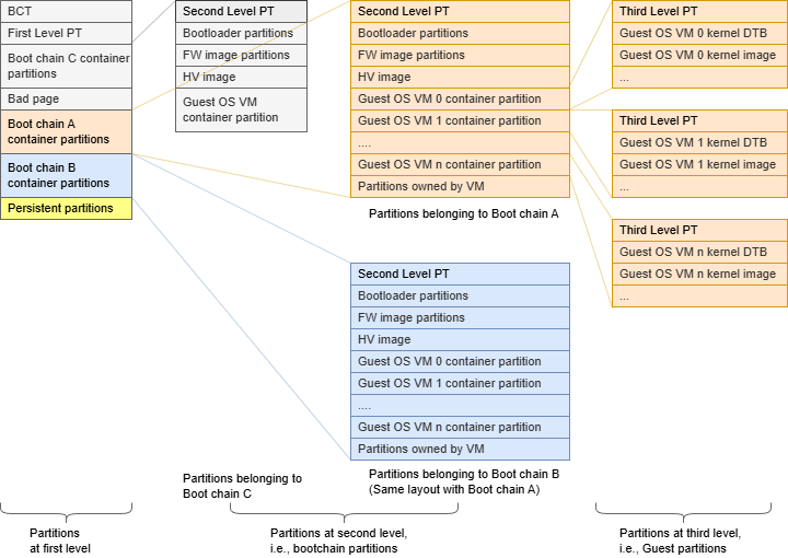
For OTA updates on QSPI/eMMC/UFS, partitions are grouped as follows:
Chain A (QSPI/UFS/eMMC): Active boot slot. Contains all QSPI, UFS, and eMMC partitions for all VMs in the PCT. OTA updates write to the inactive slot (B) while the system runs from A.
Chain B (QSPI/UFS/eMMC): Standby/alternate boot slot. Mirror structure of Chain A. After a successful OTA, the bootloader switches between A and B. This is an A/B failover slot, not the same as Chain C recovery.
Chain C (QSPI only): Minimal recovery chain on QSPI only (no UFS/eMMC). Used when the full A/B chains cannot boot or for restricted recovery scenarios.
Persistent partitions: Data partitions outside the A/B OTA cycle. Not overwritten by routine OTA updates.
When inspecting the global_storage.cfg (L1PT), you will notice it refers to boot_chain_storage.cfg as a sub_cfg_file. This elevates the boot_chain_storage.cfg to be level-2.
...
[partition]
name=A_qspi_chain
...
sub_cfg_file=boot_chain_storage.cfg

[partition]
name=B_qspi_chain
...
sub_cfg_file=boot_chain_storage.cfg

[partition]
name=C_qspi_chain
...
sub_cfg_file=boot_chain_c_storage.cfg
Similarly, when inspecting the boot_chain_storage.cfg (level-2), you will
notice it refers to the OS storage configuration file. This elevates the OS
storage configuration file to be level-3.
[partition]
name=guest-linux
...
sub_cfg_file=linux_storage.cfg
Since level-3 is derived from level-2, its content will be duplicated in each of the boot chains (A and B).
Level-1 Partition Table (L1PT) Storage Configuration Structure#
General structure of this file is:
Device 1 information [device]
Partition 1.1 information [partition]
…
Partition 1.n information [partition]
Device 2 information [device]
Partition 2.1 information [partition]
…
Partition 2.n information [partition]
etc.
Device information highlighted by this application note is:
linux_name=/dev/block/810c5b0000.spi: Name of the peripheral device.size=0x4000000: Total size of the storage device.
Note
For level-2 and level-3 configurations, the size is not the total size of the device, but the allowed size of storage device for that level, as defined in previous level partition information highlighted by this application note are:
linux_name=/dev/block/810c5b0000.spi: Name of the peripheral device.size=0xE40000: Size of the partition.
Partitions that use sub_cfg_file are container partitions. These partitions share the same space with partitions in sub_cfg_file. The size attribute specifies the allowed space that the next level can use on the device.
For the QSPI storage, the allowed space for level-2 and level-3 configurations is specified by the size.
[partition]
name=A_qspi_chain
size=0xE40000

[partition]
name=B_qspi_chain
size=0xE40000
Because level-2 and level-3 also allocate storage on eMMC/UFS, the limit on how much eMMC/UFS storage can be allocated is defined as follows:
name=A_ufs_chain
size=0xDE3000000

name=B_ufs_chain
size=0xDE3000000
Level-1 Partition Table (L1PT) partition#
The information about all partitions in Level-1, has been allocated on both QSPI and eMMC/UFS, is stored in a partition table file.
[partition]
name=pt
size=0x80000
This partition CANNOT be updated when the DU process is done. This table is common to Chain A and Chain B, so both chains’ future updates must preserve the content of Level-1 partitions. If not, DU process will fail.
Level-2 and Level-3 Partition Table (L2PT and L3PT) Storage Configuration Structure#
The level-2 and level-3 Partition Table (L2PT and L3PT) storage configuration structure follows the same rules as L1PT; that is, the general structure of this file is as follows:
Device 1.1 information [device]
Partition 1.1.1 information [partition]
…
Partition 1.1.n information [partition]
Device 2.1 information [device]
Partition 2.1.1 information [partition]
…
Partition 2.1.m information [partition]
Each level can specify partitions on QSPI and eMMC/UFS storage devices. The device record size is the maximum allowed storage space for that level, but not the full size. Both levels will affect the content of Chain A and Chain B.
Auto-Configuration Framework#
This structured approach ensures that your virtualized partitions are correctly configured according to your requirements.
It is crucial to set the
virtualizedattribute totrueif you intend for a partition to be virtualized.Users can opt for either auto-config or traditional configuration methods but should not mix both approaches for a single partition, as this could lead to undefined behavior.
If default values for any attributes are sufficient, those attributes can be omitted from configuration.
For virtualized partitions, attributes like
mempool,IVC channels, andUFS stream IDsare automatically managed by the auto-configuration framework.For
partition_attributebit, such asguest_id, is assigned based on theownerfield by the auto-configuration framework. Whenguest_idofpartition_attributeis0, the auto-configuration framework ensures no owner value is assigned, defaulting owner to null or equivalent.
Explanation of the Partition:
name: gos0-shared-pers: Sets the partition name asgos0-shared-pers.allocation_policy: sequential: Allocates storage resources sequentially for better performance.filesystem_type: basic: Specifies a minimal, basic filesystem type.size: 0x10000000: Allocates a fixed size of 256 MB (0x10000000 in hexadecimal).virtualized: true: Indicates the partition operates in a virtualized environment.owner: <GOS0_NAME>-gos0: Specifies the owner of the partition, linked toGOS0_NAME.instance: 1: Assigns the instance ID as 1 for Guest OS VM.shared: false: Marks the partition as exclusive, not shared with other entities.filename: META_DATA_IMG: SpecifiesMETA_DATA_IMGas the associated filename.ispersistent: yes: Ensures the partition retains data across reboots or power cycles.
These partitions are accessible to the Virtual Machines via inter-VM communications channels called Inter-VM-Channel (IVC), which is a bidirectional short command oriented interface, and memory pool, which is a shared memory buffer. These are only accessible by the Guest OS (QNX or Linux)/UPDATE VM and the VSC.
Reserving an IVC Queue ID:
<top>/<NV_SDK_NAME_FOUNDATION>/platform-config/hardware/nvidia/platform/t264/automotive/pct/drive_av/platform_ivc_config.h

#define RESERVED_GOS0_VSC_Q_[Ivc Queue Num]  [Ivc Queue Num]
- EXAMPLE:
#define RESERVED_GOS_VSC_Q_15 15
Note
IVC IDs must be unique. The name of the #define can be anything
that is descriptive to your organization. It is just a C preprocessing
macro that will be replaced during the binding operation.
Reserving a mempool ID:
<top>/<NV_SDK_NAME_FOUNDATION>/platform-config/hardware/nvidia/platform/t264/automotive/pct/drive_av/platform_ivc_config.h

#define RESERVED_GOS0_VSC_M_[Mempool Num] [Mempool Num]
- EXAMPLE:
#define RESERVED_GOS0_VSC_M_20 20
Note
Mempool IDs must be unique.
Additionally, the above-mentioned mempool and IVC queue need to be added to the resource.yml file in the format provided below. The bandwidth for the
mempool and IVC queues is configured sequentially using the auto-configuration method from the resource database.
<top>/<NV_SDK_NAME_FOUNDATION>/virtualization/pct/make/t264/storage_config_db/db/resource.yml

mempool_number: {
        val: [RESERVED_GOS_VSC_M_X-RESERVED_GOS_VSC_M_Y], #==> Here X to Y mempool bandwidth in a value==>#
...
...
...
}

ivc_number: {
        val: [RESERVED_GOS_VSC_Q_X, RESERVED_GOS_VSC_Q_Y], #==> Here X to Y IVC Queue bandwidth in a value==>#
...
...
...
}
Constraints
Partition sizes should be 256K aligned.
IVC queue number should be smaller than 256.
In the storage configuration file, the length of the logical partition name (the string immediately following
name=under[partition]) should be less than or equal to 23. If the partition exists in Level-2, the length should be less than or equal to 21.In the storage configuration file, the logical partition names should be unique.
DriveOS Storage Layout for DRIVE AGX Thor#
Thor Level-1 partition table(L1PT) for 64 MB QSPI, 256 GB UFS
Device |
Partition |
Size (Hex bytes) |
Mandatory |
Customizable |
Purpose |
|---|---|---|---|---|---|
QSPI |
A_bct |
0x40000(256 KiB) |
Yes |
Yes |
Chain A BCT |
B_bct |
0x40000(256 KiB) |
Yes |
Yes |
Chain B BCT |
|
C_bct |
0x40000(256 KiB) |
Yes |
Yes |
Chain C BCT |
|
pt |
0x80000(512 KiB) |
Yes |
Yes |
Partition Table |
|
C_qspi_chain |
0x2180000(33.5 MiB) |
No |
No |
Recovery chain C |
|
bad-page |
0x80000(512 KiB) |
Yes |
Yes |
For DRAM-ECC |
|
qspi_l1_reserved |
0x40000(256 KiB) |
No |
No |
Reserved for qspi ecc |
|
A_qspi_chain |
0xE40000(14.25 MiB) |
Yes |
Yes |
L1 Container for chain A |
|
B_qspi_chain |
0xE40000(14.25 MiB) |
Yes |
Yes |
L1 Container for chain B |
|
UFS LUN-0 |
A_ufs_chain |
0xDE3000000(56880 MiB) |
Yes |
Yes |
L1 UFS chain A container |
B_ufs_chain |
0xDE3000000(56880 MiB) |
Yes |
Yes |
L1 UFS chain B container |
|
gos0-shared-pers |
0x10000000(256 MiB) |
No |
Yes |
Persistent shared partition |
|
gos0-ufs |
0x1D00000000(116 GiB) |
No |
Yes |
Persistent GOS-0 storage |
|
gos0-nvlog |
0x3C00000(60 MiB) |
No |
No |
present for compatibility |
|
pers-ota |
0x10000000(256 MiB) |
No |
Yes |
Persistent GOS-0 for OTA |
|
UFS LUN-1 |
A_lun1_chain |
0x4D80000(77.5 MiB) |
Yes |
Yes |
L1 UFS chain A container |
B_lun1_chain |
0x4D80000(77.5 MiB) |
Yes |
Yes |
L1 UFS chain B container |
|
gos0_nvlog_lun1 |
0x2D00000(45 MiB) |
No |
Yes |
present for compatibility |
Thor Chain-A/B Level-2 partition table(L2PT) for 64 MB QSPI
Device |
Partition |
Size (Hex bytes) |
Mandatory |
Customizable |
Purpose |
|---|---|---|---|---|---|
QSPI |
pt |
0x40000(256 KiB) |
Yes |
No |
Partition Table |
mb1-bootloader |
0xC0000(768 KiB) |
Yes |
No |
MB1 bootloader |
|
psc-bl |
0x40000(256 KiB) |
Yes |
No |
PSC bootloader |
|
mb1-bct |
0x40000(256 KiB) |
Yes |
No |
MB1 configuration |
|
mem-bct |
0x80000(512 KiB) |
Yes |
No |
Memory configuration |
|
mem-dtb |
0x40000(256 KiB) |
Yes |
No |
BPMP Memory configuration |
|
mb2-bootloader |
0xC0000(768 KiB) |
Yes |
No |
MB2 bootloader |
|
sc7-fw |
0x40000(256 KiB) |
Yes |
No |
MB1 Resume FW |
|
mb2-rf |
0x80000(512 KiB) |
Yes |
No |
MB2 Resume FW |
|
psc-fw |
0x80000(768 KiB) |
Yes |
No |
PSC FW |
|
sb-package |
0x140000(1.25 MiB) |
Yes |
No |
SB package |
|
hpse-package |
0x440000(2.75 MiB) |
Yes |
No |
HPSE package |
|
bpmp-fw |
0x200000(1.75 MiB) |
Yes |
No |
BPMP FW |
|
bpmp-fw1 |
0x200000(1.75 MiB) |
No |
Yes |
BPMP FW for 2nd SOC SKU |
|
bpmp-fw-dtb |
0x40000(256 KiB) |
Yes |
No |
BPMP FW device tree blob |
|
bpmp-ist |
0x80000(512 KiB) |
No |
No |
BPMP IST |
|
ist-config |
0x40000(256 KiB) |
No |
No |
IST config |
|
igpu-boot-fw |
0x80000(512 KiB) |
Yes |
No |
IGPU boot FW |
|
board-info |
0x40000(256 KiB) |
No |
Yes |
Platform description |
Thor Chain-A/B Level-2 partition table(L2PT) for 256 GB UFS
L2 UFS LUN0 table
Device |
Partition |
Size (Hex bytes) |
Mandatory |
Customizable |
Purpose |
|---|---|---|---|---|---|
UFS LUN-0 |
aon-fw |
0x400000(4 MiB) |
No |
No |
Audio always on FW |
adsp0-fw |
0x400000(4 MiB) |
No |
No |
Audio FW |
|
adsp1-fw |
0x400000(4 MiB) |
No |
No |
Audio FW |
|
dce-fw |
0x1000000(16 MiB) |
Yes |
No |
DCE FW |
|
pva-fw |
0x280000(2.5 MiB) |
Yes |
No |
PVA FW |
|
atf |
0x40000(256 KiB) |
Yes |
No |
ARM trusted FW |
|
secure-hv |
0x500000(5 MiB) |
Yes |
No |
Secure Hypervisor FW |
|
fsi-fw |
0x1500000(21 MiB) |
Yes |
No |
FSI FW |
|
plat-misc-fsi |
0x140000(1.25 MiB) |
No |
Yes |
Platform MISC for FSI |
|
rce-fw |
0x100000(1 MiB) |
Yes |
No |
RCE FW |
|
rce-fw-dtb |
0x80000(512 KiB) |
Yes |
No |
RCE FW DTB |
|
pvit |
0x40000(256 KiB) |
Yes |
No |
Partition version info |
|
kernel |
0x1900000(25 MiB) |
Yes |
No |
Hypervisor kernel |
|
xusb-fw |
0x40000(256 KiB) |
No |
No |
USB FW |
|
ist-testimg |
0x100000000(4 GiB) |
No |
No |
IST test images |
|
ist-runtimeinfo |
0x40000(256 KiB) |
No |
No |
IST runtime data |
|
gr-ist |
0x40000(256 KiB) |
No |
No |
IST runtime data |
|
gos0-fs |
0x680000000(26 GiB) |
Yes |
Yes |
GOS0 OS Root Filesystem |
|
guest-linux |
0x4BC0000(75.75 MiB) |
Yes |
Yes |
L3 Linux guest config |
|
gos0-rw-ovrlay |
0x40000000(1 GiB) |
No |
Yes |
RW partition for RO rootfs |
|
gos0-kdump |
0x10000000(256 MiB) |
No |
Yes |
kdump/crash kernel storage |
|
gos0-crashlogs |
0x100000(1 MiB) |
No |
Yes |
Crash log partition |
|
custom |
0x380000(3.5 MiB) |
No |
Yes |
L3 GPT container partition |
|
nvlog-server-rw (alias-nvlog-gos-ro) |
0x20000000(512 MiB) |
Yes Yes |
No No |
NVLOG partition to store logs |
L2 UFS LUN1 table
Device |
Partition |
Size (Hex bytes) |
Mandatory |
Customizable |
Purpose |
|---|---|---|---|---|---|
UFS LUN-1 |
ist-resultdata |
0x3700000(77.5 MiB) |
Yes |
No |
IST test results in LUN1 |
Thor Chain-A/B Level-3 partition table(L3PT) for 256 GB UFS
Device |
Partition |
Size (Hex bytes) |
Mandatory |
Customizable |
Purpose |
|---|---|---|---|---|---|
UFS LUN-0 |
pt |
0x40000(256 KiB) |
Yes |
No |
Partition table |
kernel-dtb |
0x100000(1 MiB) |
Yes |
No |
OS kernel device tree blob |
|
kernel |
0x3F80000(63.50 MiB) |
Yes |
No |
OS kernel |
|
ramdisk |
0xB00000(11 MiB) |
Yes |
No |
initramfs image |
Thor Chain-C Level-2 partition table(L2PT) for 64 MB QSPI
Device |
Partition |
Size (Hex bytes) |
Mandatory |
Customizable |
Purpose |
|---|---|---|---|---|---|
QSPI |
pt |
0x40000(256 KiB) |
Yes |
No |
Partition Table |
mb1-bootloader |
0xC0000(768 KiB) |
Yes |
No |
MB1 bootloader |
|
psc-bl |
0x40000(256 KiB) |
Yes |
No |
PSC bootloader |
|
mb1-bct |
0x40000(256 KiB) |
Yes |
No |
MB1 configuration |
|
mem-bct |
0x80000(512 KiB) |
Yes |
No |
Memory configuration |
|
mem-dtb |
0x40000(256 KiB) |
Yes |
No |
BPMP Memory configuration |
|
mb2-bootloader |
0xC0000(768 KiB) |
Yes |
No |
MB2 bootloader |
|
psc-fw |
0xC0000(768 KiB) |
Yes |
No |
PSC FW |
|
sb-package |
0x140000(1.25 MiB) |
Yes |
No |
SB package |
|
hpse-package |
0x440000(2.75 MiB) |
Yes |
No |
HPSE package |
|
bpmp-fw |
0x200000(1.75 MiB) |
Yes |
No |
BPMP FW |
|
bpmp-fw1 |
0x200000(1.75 MiB) |
No |
Yes |
BPMP FW for 2nd SOC SKU |
|
bpmp-fw-dtb |
0x40000(256 KiB) |
Yes |
No |
BPMP FW device tree blob |
|
pvit |
0x40000(256 KiB) |
Yes |
No |
Partition version info |
|
atf |
0x40000(256 KiB) |
Yes |
No |
ARM trusted FW |
|
secure-hv |
0x100000(768 KiB) |
Yes |
No |
Secure Hypervisor FW |
|
fsi-fw |
0xC0000(768 KiB) |
Yes |
No |
FSI FW |
|
kernel |
0x200000(2 MiB) |
Yes |
No |
Hypervisor kernel |
|
guest-linux-chain_c |
0x1200000(18 MiB) |
Yes |
No |
L3 Linux guest config |
Thor Chain-C Level-3 partition table(L3PT) for 64 MB QSPI
Device |
Partition |
Size (Hex bytes) |
Mandatory |
Customizable |
Purpose |
|---|---|---|---|---|---|
QSPI |
pt |
0x40000(256 KB) |
Yes |
No |
Partition table |
kernel-dtb |
0x80000(512 KB) |
Yes |
No |
OS kernel device tree blob |
|
kernel |
0x840000(8.25 MiB) |
Yes |
Yes |
Recovery OS kernel |
|
ramdisk |
0x900000(9 MB) |
Yes |
Yes |
Recovery initramfs image |
Out Directory of CUE-lang file configuration#
After you complete the Bind Partition Process, the following steps occur:
CUE Compilation:
The system compiles the CUE files, and the corresponding storage layout is provided as the YAML file
cue_storage_config.yaml.YAML to Storage Configuration:
The generated YAML file serves as input to the YAML-to-Converter Tool, which processes it to produce the required storage configuration files
Output Location:
You can find the resulting storage configuration files in the following locations:
Output directory paths:
Linux platform:
<top>/<NV_SDK_NAME_FOUNDATION>/virtualization/hypervisor/t26x/configs/t264ref-release/pct/<BOARD-NAME>/cue_config_support/out
tree -l
.
├── boot_chain_c_storage.cfg
├── boot_chain_storage.cfg
├── cue_storage_config.yaml
├── custom_storage_ufs.cfg
├── global_storage.cfg
├── linux_chain_c_storage.cfg
└── linux_storage.cfg

0 directories, 7 files
Out Directory of Auto-config Storage Framework#
After the Bind Partition process is completed, the auto-configured dataplanes
and the required DT nodes with auto-configured IVC queues, mempool ID, and
ufs_stream_id can be found in the following location:
Note
Provided the out directory for the PCT : LINUX
<top>/<NV_SDK_NAME_FOUNDATION>/virtualization/hypervisor/t26x/configs/t264ref-release/pct/<BOARD-NAME>/auto_config/out

tree -l
.
├── auto_config_linux_gos0_storage.dtsi
├── boot_chain_c_storage.cfg
├── boot_chain_storage.cfg
├── custom_storage_ufs.cfg
├── drive_updatedu_hvrtos.dt
├── global_storage.cfg
├── linux_chain_c_storage.cfg
├── linux_storage.cfg
└── storage_linux-gos0.dts

0 directories, 9 files
auto_config_linux_gos0_storage.dtsi consists of the auto-generated address-space node, context bank node, memory mapping node, as well as the virtual storage DT node, for example:
<top>/<NV_SDK_NAME_FOUNDATION>/virtualization/hypervisor/t26x/configs/t264ref-release/pct/<BOARD-NAME>/auto_config/out/auto_config_linux_gos0_storage.dtsi


tegra_virt_storage79{
    compatible="nvidia,tegra-hv-storage";
    status="okay";
    iommus=<&smmu1_mmu 0x2a01>;
    instance=<1>;
    ivc=<&tegra_hv 59>;
    mempool=<19>;
    partition-name="gos0-shared-pers";
    };
Verify the configurations using the auto-configured UFS Stream ID:
<top>/<NV_SDK_NAME_FOUNDATION>/virtualization/hypervisor/t26x/configs/t264ref-release/pct/<BOARD-NAME>/auto_config/out/global_storage.cfg

[partition]
name=gos0-shared-pers
resize=yes
allocation_policy=sequential
filesystem_type=ext4
size=0x10000000
partition_attribute=0x1              /* Auto-configured partition_attribute */
ufs_stream_id=0x2A01                 /* Auto-configured ufs stream id */
virtual_storage_ivc_ch=0x8316133B    /* Auto-configured ivc channel */
filename=<PDK_TOP>/drive-linux/filesystem/targetfs-thor-user-metadata.img
ispersistent=yes
virtual_storage_ivc_ch=0x8316[Hex value of Mempool Num][Hex value of Ivc Queue Num]
The 32-bit value of virtual_storage_ivc_ch can be broken down as follows:
Bit |
Description |
|---|---|
[31] |
Is Virtual Storage Flag [virt = 1, non-virt = 0] |
[30:24] |
Storage Server ID [int value from 0-0x7F] |
[23] |
Shared Partition Flag [shared = 1, exclusive = 0] |
[22] |
RESERVED |
[21:18] |
Partition Priority. [Values from 1 through 5, where 1 is the highest priority.] |
[17] |
Disable pass-through [1 = Disable, 0 = Enable] |
[16] |
Read only flag [RO =1, RW = 0] |
[15:8] |
Mempool ID [int value from 0-0xFF] |
[0:7] |
IVC Queue ID [int value from 0-0xFF] |
The 32-bit value of partition_attribute can be broken down as follows:
Bit |
Description |
|---|---|
[31] |
Set if the partition’s storage device is the boot medium for the guest. |
[30] |
Set if the partition holds a blob for boot-chain (and sub_cfg_file is present if the partition is present on the global boot device). |
[29] |
Set if the partition holds a blob for guest partitions (and sub_cfg_file is present). |
[28] |
Set if the partition holds a blob for user partitions (and sub_cfg_file is present). |
[0:4] |
guest ID [int value from 0-31] |
GPT L3 Support#
GUID-based partition table (GPT) support is added for Guest OS at L3 level. With this feature, the partitions in L3 under GPT can be independently updated including the partition table.
To add a GPT partition at the third level (L3), a container partition needs to be added to the second level (L2). L2 level container partition holds the GPT primary and backup partition layout along with the actual partition contents.
The diagram below shows the organization of L2 container partition for GPT.
Figure 2. Organization of L2 GPT Partition Example 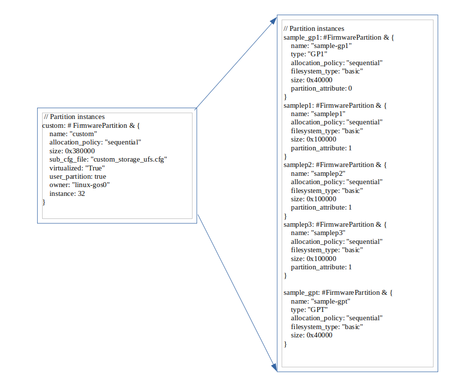 In the preceding example, the
 custom partition is the
container partition. In order for the flashing tools to create GPT partition
layout, the first partition must be of type GP1 and the last partition must
be of type GPT. Flashing tools would create GPT primary and back up
partitions when such an arrangement exists.
Multiple GPT partitions can be added for the same guest. The GPT primary and secondary are generated by using the container partition name as prefix.
Caution and Verification
The size of the device at L3 matches the size of the extended custom partition at L2:
The custom container has three partitions each of 1 MB. Note that the filename is not specified above. If file is not specified, flash tools will not create any images for these partitions but the space is allocated and will be formatted if specified. If an image is required, update the partition within the custom cfg file accordingly to add the filename field and point it to the file you want to flash.
Once booted with upper changes, the GPT partitions are enumerated as virtual block devices in Guest OS.
For Linux, if the container block device is enumerated as /dev/vblkdev32, then the individual partitions are /dev/vblkdev32p1, /dev/vblkdev32p2, and /dev/vblkdev32p3.
Configuring the UFS Stream ID for Virtualized UFS Partitions#
The ufs partitions that are virtualized will need a unique stream ID
associated with it. To make this work, storage config is extended with a new
attribute ufs_stream_id. The attribute ufs_stream_id becomes
auto-configured by the auto-config framework.
These stream ID macros are defined in tegra264-smmu-streamid-ufs.h:
<top>/<NV_SDK_NAME_FOUNDATION>/platform-config/hardware/nvidia/t264/nv-public/include/kernel-t264/dt-bindings/memory/tegra264-smmu-streamid-ufs.h
#define TEGRA264_SID_UFS_X  (TEGRA264_SID_UFS + 0x01)
#define TEGRA264_SID_UFS_Y  (TEGRA264_SID_UFS + 0x02) /*Here X to Y  bandwidth in a value */
Additionally, the above-mentioned mempool and IVC queue must be added to the
resource.yml file in the following format. The bandwidth for the
mempool and IVC queues is configured sequentially using the auto-configuration
method from the resource database.
<top>/<NV_SDK_NAME_FOUNDATION>/virtualization/pct/make/t264/storage_config_db/db/resource.yml

ufs_stream_id: {
        val: [TEGRA264_SID_UFS_X-TEGRA264_SID_UFS_Y],Here X to Y  bandwidth in a value==>#
...
...
...
}
Enabling UFS Inline Encryption and Configuring Key Index for Each Partition#
When the ENABLE_UFS_ENCRYPT=y option is provided during bind_partitions, UFS Inline Encryption is enabled. When UFS Inline Encryption is enabled, the following two properties are added to predefined UFS partitions in L2PT that require encryption:
ufs_inline_encryption=trueufs_key_index=[Key Index Number]
The [Key Index Number] for ufs_key_index is defined in the ufs_encrypt_key_idx_header.cfg file.
This mapping file ensures that unique key index numbers remain consistent across releases.
Example:
<top>/<NV_SDK_NAME_FOUNDATION>/platform-config/hardware/nvidia/platform/t264/automotive-platform-configs/driveos_internal_config/storage_config/drive_av/linux/boot_chain_storage.cue

gos0_fs: #rootfs_partition & {
    name: "gos0-fs"
    allocation_policy: "sequential"
    virtualized: true
    if ENABLE_UFS_ENCRYPT == "y" {
        ufs_inline_encryption:true
        ufs_key_index: "KEY_IDX_GOS0_LNX_RFS"
    }
}
<top>/<NV_SDK_NAME_FOUNDATION>/platform-config/hardware/nvidia/platform/t264/automotive/pct/drive_av/ufs_encrypt_key_idx_header.cfg

/*
 * =============================================================================
 * GUEST OS 0 (0~9), (50~59)
 * =============================================================================
 */
#define KEY_IDX_GOS0_LNX_RFS            0
#define KEY_IDX_GOS0_LNX_RW_OVERLAY     1
#define KEY_IDX_GOS0_LNX_CRASH_LOG      2
#define KEY_IDX_GOS0_QNX_RFS            3

....

/*
 * =============================================================================
 * ETC (40~49)
 * =============================================================================
 */
#define KEY_IDX_NVLOG_SERVER_RW        40
#define KEY_IDX_IST_RESULTDATA         41

....

/*
 * =============================================================================
 * Reserved for Customer (60~127)
 * =============================================================================
 */
#define KEY_IDX_RESERVED_60           60
Adding Customer-Configurable Partitions with UFS Inline Encryption#
If a customer-configurable partition is added in L2PT UFS and UFS Inline Encryption needs to be applied, add:
ufs_inline_encryption=trueufs_key_index=[Key Index Number 60~127]
Key index values 0~59 are reserved for NVIDIA mandatory partitions. Here is an example of adding two UFS Inline Encrypted partitions:
<top>/<NV_SDK_NAME_FOUNDATION>/platform-config/hardware/nvidia/platform/t264/automotive-platform-configs/driveos_customer_config/nv_platforms/common/storage_config/drive_av/linux/cust_boot_chain_storage.cue

cust_pt_1: #custom_oem & {
....
    if ENABLE_UFS_ENCRYPT == "y" {
        ufs_inline_encryption:true
        ufs_key_index: "KEY_IDX_CUST_PT_1"
    }
}

cust_pt_2: #custom_oem & {
....
    if ENABLE_UFS_ENCRYPT == "y" {
        ufs_inline_encryption:true
        ufs_key_index: "KEY_IDX_CUST_PT_2"
    }
}
<top>/<NV_SDK_NAME_FOUNDATION>/platform-config/hardware/nvidia/platform/t264/automotive/pct/drive_av/ufs_encrypt_key_idx_header.cfg

....

/*
 * =============================================================================
 * Reserved for Customer (60~127)
 * =============================================================================
 */
#define KEY_IDX_CUST_PT_1           60
#define KEY_IDX_CUST_PT_2           61
Multiple UFS LUN Configuration#
By default, DriveOS uses a multiple LUN configuration. In the following configuration, the 256 GB drive is split into two logical LUNs:
238 GB for the main storage device
200 MB for heavy writing logging applications
If you do not want to use the logging LUN, add ENABLE_UFS_LUN1=n to the bind command. For example:
bind_partitions -b p3960-10-sw01 av.linux ENABLE_UFS_LUN1=n
If you do want to use the LUN, ensure your platform has been reprovisioned for two LUNs.
Warning
Provisioning a UFS device wipes all data on it. Please make sure to back up all important data before provisioning.
To provision UFS, you will need a BSP created by flashtools
create_bsp_images.py. This is a one time execution. You do not need to
provision again unless the LUN sizes change or new LUNs are added. For more
information on how to provision the UFS LUNs, see To Provision a UFS Device through the Flashing Tools.
Steps to follow:
Create the BSP and push to the host where the target is connected.
Set the target in recovery.
Flash the target with an additional
-Uoption. Pass the absolute path to the provision configuration file, per the following locations:
<top>/<NV_SDK_NAME_FOUNDATION>/tools/flashtools/storage_config/t264/ufs-provision-<size>.cfg
You can also create a custom configuration file and provide its path.
After successful provisioning, put the board back in recovery.
Flash the target as normal.
Example flash commands for p3960-10-sw01 DRIVE-AGX Thor DevKit (assume bsp_image contains output of create BSP):
cd bsp_imageWithin MCU:
tegrarecovery x1 onWithin MCU:
tegrareset x1Provision the board:
./tools/flashtools/bootburn/flash_bsp_images.py -b p3960-10-sw01 -P $PWD/642-63960-0010-000_TS1 -U $PWD/tools/flashtools/storage_config/t264/ufs-provision-256gb.cfg -D
Within MCU:
tegrareset x1Flash the board:
./tools/flashtools/bootburn/flash_bsp_images.py -b p3960-10-sw01 -P $PWD/642-63960-0010-000_TS1 -D
The following output should be seen in the flashing kernel after successful provision:
program_lun_debugfs_write: LUN Programming successful
To verify that the board has been provisioned, check for the following in the boot logs:
[ 1.266460] scsi 0:0:0:49488: Well-known LUN MICRON MT256GBCAV4U31AA 0301 PQ: 0 ANSI: 6
[ 1.279496] sd 0:0:0:0: [sda] 62236672 4096-byte logical blocks: (255 GB/237 GiB)ANSI: 6I: 6
[ 1.279502] scsi 0:0:0:1: Direct-Access MICRON MT256GBCAV4U31AA 0301 PQ: 0 ANSI: 6
[ 1.279797] sd 0:0:0:0: [sda] Write Protect is off
[ 1.280109] sd 0:0:0:0: [sda] Write cache: enabled, read cache: enabled, supports DPO and FUA
[ 1.280111] sd 0:0:0:0: [sda] Preferred minimum I/O size 4096 bytes
[ 1.283075] sd 0:0:0:1: [sdb] 51200 4096-byte logical blocks: (210 MB/200 MiB)
[ 1.283251] sd 0:0:0:1: [sdb] Write Protect is off
[ 1.283580] sd 0:0:0:1: [sdb] Write cache: enabled, read cache: enabled, supports DPO and FUA
[ 1.283583] sd 0:0:0:1: [sdb] Preferred minimum I/O size 4096 bytes
If you attempt to flash a board with multiple LUNs that has only been provisioned for a single LUN, the VSC server will show the following error:
Error opening device ufs_lun1
hv_storage: unable to allocate client for ufs_lun1
error setting up post init for virt storage device 4
Programming error:
vsc/hvrtos/virtual_device_manager/vsc_dev_mgr.c:636:"FATAL ERROR: ASSERT"

STACK TRACE:
0x24b30
0x24738
0x239c0
0x42484
Storage Device Passthrough Access#
For internal testing purpose, the passthrough access is selectively enabled for following:
PCT (variant) type |
Passthrough enabled partition name |
|---|---|
DRIVE AV :Linux PCT |
GOS0 OS Root Filesystem |
Note
We recommend that you enable storage passthrough access (if required) only for one virtual storage partition of a physical storage device. See the Virtual Partitions section for details about how to enable passthrough access using 32-bit virtual_storage_ivc_ch value for a virtual partition.