
Heterogeneous Frame Synchronization#
Note
This function requires hardware support, which is available on P3710-10-a04, p3710-10-s05, p3710-12-a04, p3710-12-s05, and P3960. Refer to the NVIDIA DriveOS Linux Installation Guide for additional information.
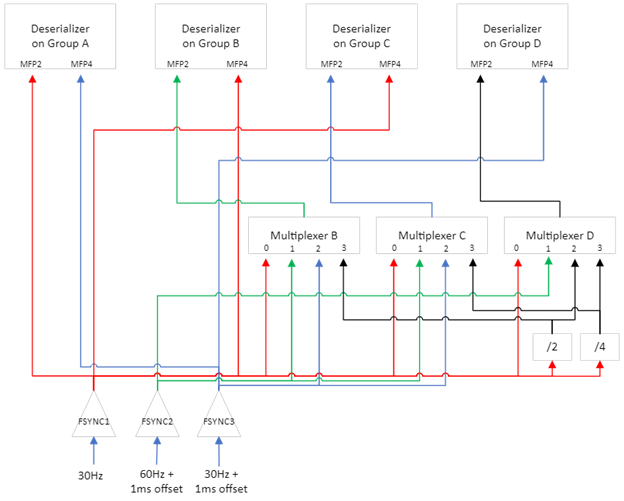
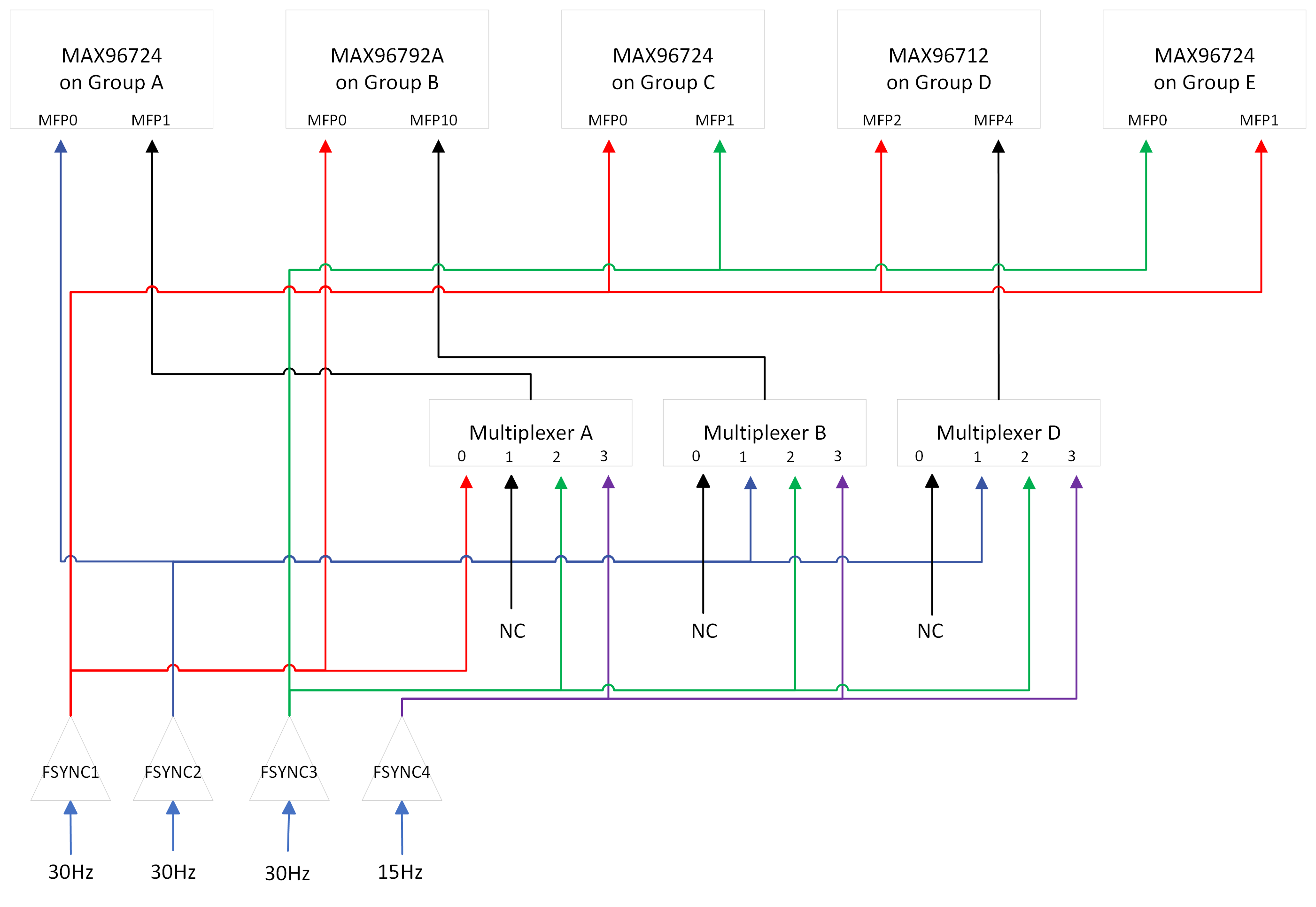
TSC_EDGE_OUT signals are used as FSYNC signals supplied to sensors through the deserializer and the serializer, and 3 x TSC_EDGE_OUT signals are applicable on P3710-10-a04, p3710-10-s05, p3710-12-a04, p3710-12-s05 and 4 x TSC_EDGE_OUT signals are applicable on P3960. Each TSC_EDGE_OUT signal is preconfigured with the same or different frequencies in the device tree while the OS boots up, and they are supplied to each deserializer directly, or through the multipliers and multiplexers to provide the different FSYNC signal options for the different use cases.
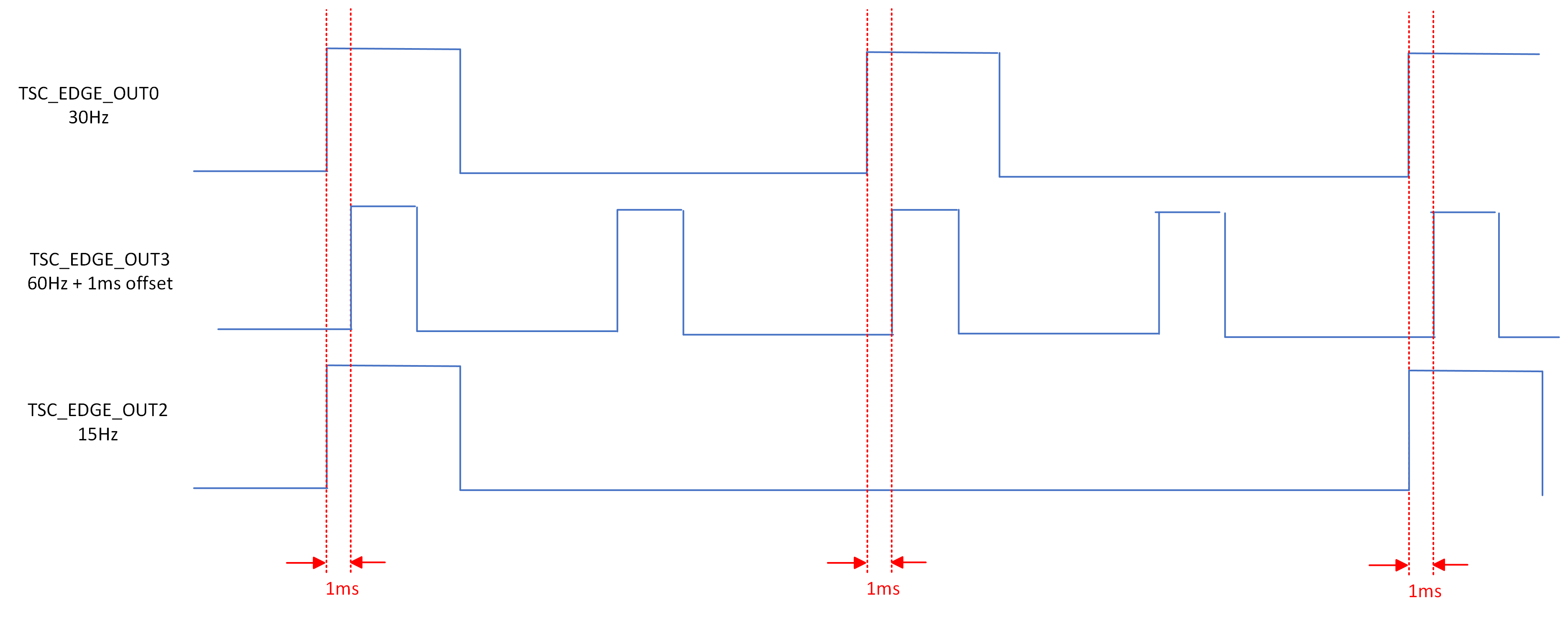
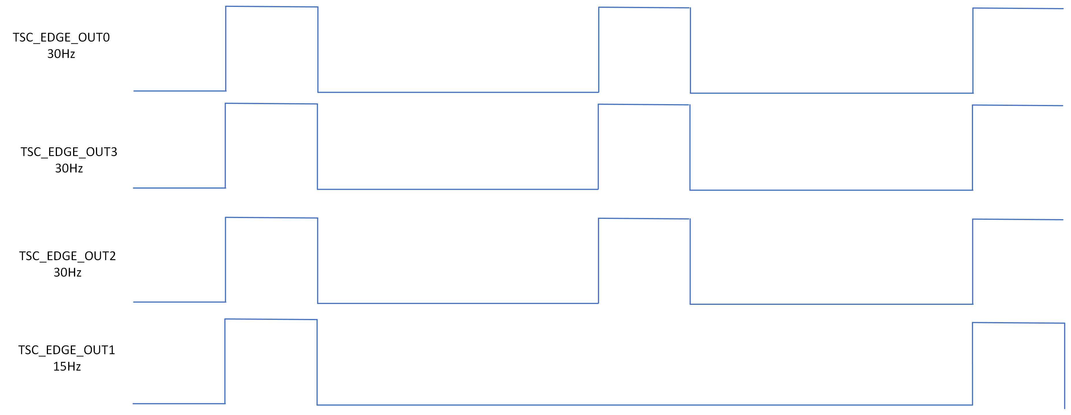
The deserializer selects one FSYNC and forwards it to the camera module selectively. The following image is an example use case to select the different FSYNC signal as a source of each camera module. The hardware block image, below, indicates how each FSYNC signal is routed. The timing diagram indicates what frequencies are configured and what offset is used among mutiple TSC_EDGE_OUT signals in the SDK and SDK by default. If different frequencies or offsets are required, refer to Fsync Signal Generation for more information.
Example of forwarding two different FSYNC signals to different camera modules:
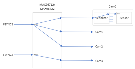
Hardware block diagram to support heterogeneous frame synchronization:
P3710-10-a04, p3710-10-s05, p3710-12-a04, p3710-12-s05
TSC_EDGE_OUT Number |
Nodes in Device Tree |
|
|---|---|---|
FSYNC1 |
TSC_EDGE_OUT0 |
gen0: generator@380 |
FSYNC2 |
TSC_EDGE_OUT3 |
gen3: generator@500 |
FSYNC3 |
TSC_EDGE_OUT2 |
gen2: generator@480 |
Timing diagram among 3 x FSYNC signals:
P3960
TSC_EDGE_OUT Number |
Nodes in Device Tree |
|
|---|---|---|
FSYNC1 |
TSC_EDGE_OUT0 |
gen0: generator@380 |
FSYNC2 |
TSC_EDGE_OUT3 |
gen3: generator@500 |
FSYNC3 |
TSC_EDGE_OUT2 |
gen2: generator@480 |
FSYNC4 |
TSC_EDGE_OUT1 |
gen1: generator@400 |
Timing diagram among 4 x FSYNC signals:
Reference Codes#
The deserializer driver (MAX96712DeserializerDriver_nv) provides a custom interface API, SetHeteroFrameSync, to select the MFP pins per link and to control the multiplexer, located in drive-<OS>/samples/nvmedia/nvsipl/devblk/devblk_new/devices/MAX96712DeserializerDriver_nv/CNvMMax96712_Fusa_nv.cpp. The SetHeteroFrameSync API calls two sub APIs, MAX96712WriteParameters(), withCDI_WRITE_PARAM_CMD_MAX96712_SET_HETERO_FRAME_SYNC to select MFP of the deserializer as a FSYNC source for the camera module per link and DevBlkCDISetFsyncMux() to change the input source of the multiplexer associated with the specific deserializer.
The nvsipl_camera sample application (drive-<OS>/samples/nvmedia/nvsipl/test/camera) provides two command options to support the heterogeneous frame synchronization and calls the SetHeteroFrameSync API to configure the MFPs and the multiplexer per deserializer.
--syncGPIOIdxDes 'gpios'
: MFP pin index is a list of MFP pins for each deserializer.
- Eg:
‘2 2 2 2 2 2 2 2 2 2 2 2 2 4 2 4’ use MFP4 for the link 1 and 3 on CSI-GH interface and MFP2 is used for other links.
--syncMuxSelDes 'Indexes'
:Selection index to the multiplexer. Applicable only for the specific board.
:Index is a list of selection index for each deserializer.
- Eg:
‘1 2 3’ selects the selection index 1 for the multiplexer on the deserializer on the camera group B, the selection index 2 for the multiplexer on CSI-EF, and the selection index 3 for the multiplexer on CSI-GH.